Abstract
Next generation, additively-manufactured metallic parts will be designed with application-optimized geometry, composition, and functionality. Manufacturers and researchers have investigated various techniques for increasing the reliability of the metal-AM process to create these components, however, understanding and manipulating the complex phenomena that occurs within the printed component during processing remains a formidable challenge—limiting the use of these unique design capabilities. Among various approaches, thermomechanical modeling has emerged as a technique for increasing the reliability of metal-AM processes, however, most literature is specialized and challenging to interpret for users unfamiliar with numerical modeling techniques. This review article highlights fundamental modeling strategies, considerations, and results, as well as validation techniques using experimental data. A discussion of emerging research areas where simulation will enhance the metal-AM optimization process is presented, as well as a potential modeling workflow for process optimization. This review is envisioned to provide an essential framework on modeling techniques to supplement the experimental optimization process.
Keywords: metal additive manufacturing, 3D Printing, thermomechanical modeling, finite element methods, residual stress
Graphical abstract
1. Introduction
Additive manufacturing (AM), or 3D Printing, has revolutionized the manufacturing industry – all the way from developing concept models to creating functional parts, and is now driving the next generation of engineering design and innovation. By decreasing the cost of complex components and enabling game-changing designs, AM has significantly impacted many industries [1–9]. Its continued growth has elicited new manufacturing applications and demand for increased processing reliability for the next generation of the technology, which includes application-optimized design, or the leveraging of additive processes to generate components that have geometry, material properties, and functionality optimized for the intended application. This design capability includes software tools that allow engineers and designers to predict each component’s processing and performance capabilities, lowering production costs and increasing design efficiency. Such groundbreaking technology requires a foundational understanding of the underlying AM-processing physics to address the challenges that are inherent in printing a component with varying features, composition, and capabilities. One of the main roadblocks is a full understanding of relationships between processing parameters and final part properties for components that have unique features and/or material properties [10,11]. Because of the complex thermal phenomena that occurs during the printing process, particularly for metallic parts, variability in final part properties can be extremely high. It is important to acknowledge that AM is based on layer-by-layer processing using powder as a starting material for most metallic-AM technologies. Defects such as pin hole voids, incomplete melting or incomplete filling is common in any layer while >99% of the part may be defect free. The challenge is to detect and repair these defects as they happen, or stop the printing process altogether – tasks that are extremely challenging. To accomplish a part with 0% critical size defect requires optimization of the CAD file, its conversion to a surface file, in addition to all AM processing parameters for that specific machine. This challenge typically requires manufacturers to conduct large scale parametric studies to understand how effectively a designed component could be processed via additive. As an example, when manufacturers are first developing an additive-based manufacturing procedure for a specific component or material, small test samples are printed with varying process parameters to determine the optimal processing conditions for achieving desired properties. While this typically results in information that can help drive the parameter choice process, it may not be applicable for parts with large and/or complex geometrical features. Other less common in situ process optimization methods such as on-line process monitoring and in-line quality control have also been investigated, but are challenging to implement reliably into existing machine technologies [12–14]. The use of volumetric heat-source energy density to optimize printing parameters has also been investigated, but has been shown to lack necessary information about the thermal phenomena that occurs during the process, and can be too generalized to apply to many different material systems [15]. In general, these techniques require significant setup time and materials which quickly increase production costs and are largely non-transferable among material systems and machines. Because of these challenges, researchers and machine manufacturers are developing new, innovative approaches, such as process simulation. The main driving force for modeling is that it requires no raw materials or machine use, thereby reducing overall time, resources, and potential machine damage [16–18]. In many cases, having a successful first print is the most challenging task for developing an additive-based manufacturing process, which is where simulation can play a vital role in identifying problems along several length scales. One of these model types is thermomechanical simulation, whereby, temperature history and residual stresses at the part-scale are predicted. These parameters are known to play a significant role in processing variability and variation in final part properties. While it is understood that experiment-based final optimization is necessary for substantiating the process, it is envisioned that thermomechanical modeling will become a mainstay tool for engineers and manufacturers to gain fundamental insights early in the design cycle, and supplement experimental parameter optimization techniques [19]. The widespread implementation of modeling will ultimately lead to a more economic overall manufacturing process because critical components that require days to weeks to manufacture could be saved from becoming scrap through predictive modeling. Additionally, new additive applications will significantly benefit from thermal modeling of AM, such as multi-material additive manufacturing, alloy development, topology optimization, which all individually contribute to application-optimized design methodology. With increases in computational power and the need to meet increasing design requirements while simultaneously saving cost and time, thermal modeling of additive manufacturing phenomena will be used as often as structural or thermal analyses are used by engineers for application-specific simulation in the engineering design process. While it shows promise, much of the literature to date is meant to be understood by experts in the thermal modeling/numerical analysis field, and not for experimentalists or a general audience interested in gaining fundamental insights. Among relevant review papers, Galati et al. (2018) and Thompson et al. (2015) have surveyed some of the complex transport phenomena and modeling for EBM and DED processes, and Zeng et al. (2012) provided an early review of initial thermal analysis techniques [20–22]. In addition, Francois et al. (2017) reviewed some of the current challenges and length scales associated with additive manufacturing modeling [16]. In a significant amount of the literature, however, authors are focused solely on developing numerical models, leaving experimental validation, the potential for direct applications, and an emphasis on the fundamental phenomena lacking. The primary focus of this work is to provide coherence to an otherwise scattered landscape of modeling efforts and emerging techniques of AM across the literature, as well as how they might play a role in future applications. The fundamentals of modeling directed energy deposition (DED) and powder bed fusion (PBF) thermal phenomena are discussed [23]. In addition, techniques for validating these models, as well as future applications and perspectives on thermal modeling are discussed.
2. Metallic AM – Towards Processing Simulation
ASTM has developed a widely-acknowledged classification standard that distinguishes additive manufacturing processes into seven main categories, each defined by the mechanics of the layer-by-layer building process [24]. Out of the seven designated categories, directed-energy-deposition (DED) and powder-bed-fusion (PBF) techniques are most known for their ability to manufacture functional metal components with properties that rival those of traditional processing techniques while requiring minimal post-processing steps [23]. Both PBF and DED techniques utilize a laser or electron beam to melt metal powder or wire that solidifies in a layer-by-layer manner (see Figure 1). The primary difference between the two techniques is that DED utilizes a powder flow/wire feedstock system to direct material onto the build substrate while simultaneously tracing out the build layer, whereas in the case of PBF, the powder is already within the build chamber and the energy source need only trace out each layer. A comparison of these techniques, as well as their overall advantages and disadvantages, can be found in review articles from Debroy (2018) as well as Tofail (2017) [1,2]. Some examples of components enabled through these two processes are porous biomedical implants [25–28], internal cooling channels and embedded features [29,30], location-specific coatings [31–33], multi-material and compositionally graded structures [34–37], part repair [38–40], among others (see Figs. 1A–1F). Investigation of any of these innovative designs hinges on a printer’s ability to reliably operate according to the machine operator’s inputs, otherwise manufacturers become hesitant to explore new concepts, such as application-optimized design. Increasing reliability requires a deep understanding of how AM processing parameters play a role in the as-printed product. Some of these aspects include the as-printed microstructure, defects, porosity, and warping, among others [1,41–43]. Pores and powder balling can emerge due to either excessive or insufficient laser power for a given scan speed. The “keyhole effect” occurs when too high power is used at low scan speeds, and the heat source penetrates deep into the material [42,44,45]. These pores can become sources of stress concentration in the part and can lead to crack propagation and failure during processing, or even under more alarming circumstances such as during part operation (see Figure 2). Teng et al (2017) reviewed some of these main defect modes as well as some modeling techniques for understanding their origin [45]. Damage tolerance and defect prediction requires significant attention due to the challenge of making seemingly-perfect, defect-free metal components. Because large, or highly complex, components can require days or weeks to finish printing, inconsistencies and failures are incredibly costly. As an example, if improper parameters are chosen for a 10,000-layer component, the potential for a defect on any layer can result in a scrapped component. Each machine, whether DED or PBF-based, has different operating parameters (input power, scan speed, hatch spacing, etc.), and choosing the optimal combination is often a significant undertaking involving trial and error methods for each material, geometry, and desired as-printed part properties. These methods are time-intensive, require extensive raw materials, and are not always successful in identifying optimal processing parameters for specific applications. As an example, a single material may work well with additive processes and the parameter optimization is straightforward for printing small samples, but more complex geometries may require additional experimentation and optimization. These situations are becoming increasingly commonplace and warrant the use of supplemental methods and tools to identify optimal process parameters, such as thermomechanical process modeling. These techniques can significantly enhance the experimentation process by providing a quick feedback loop to designers (see Figure 3A). It is more efficient than experimental techniques alone because it does not require processing time, sample preparation, and extensive characterization methods, which may require weeks or months for feedback. With simulation, a few days may be all that is required to run an effective set of simulations. This does come at a cost, however, as simulation time and accuracy are inherent challenges to providing effective information to machine users Nevertheless, thermomechanical modeling software has already reached first-generation commercialization via companies such as 3DSim (recently acquired by ANSYS), Simufact, NetFabb Simulation (formerly Pan Computing), and GEONX (a part of GE Additive) [46–48], among others, and is envisioned to reach a level of use similar to how extensively finite element software is employed to predict application-based structural or thermal response to specific engineering situations. Figure 3B provides an indication of the current state of modeling additive manufacturing-related phenomena on several different length scales. Microstructural and mesoscale modeling has been investigated to model phenomena such as grain growth and phase formations [49,50], and integrated approaches have been made to combine different length scale simulations [51,52]. The more commonly employed simulations for end-users, however, are on the part level i.e. the macro scale, and involve thermomechanical modeling methods such as finite-element or finite-difference schemes. Many researchers have used finite element modeling packages to model macroscale AM processing phenomena (see Table 1), but there is a significant need to provide easy integration to existing CAD architecture, simplify our understanding of residual stress formation, and address emerging techniques and applications of metal-AM.
Figure 1:
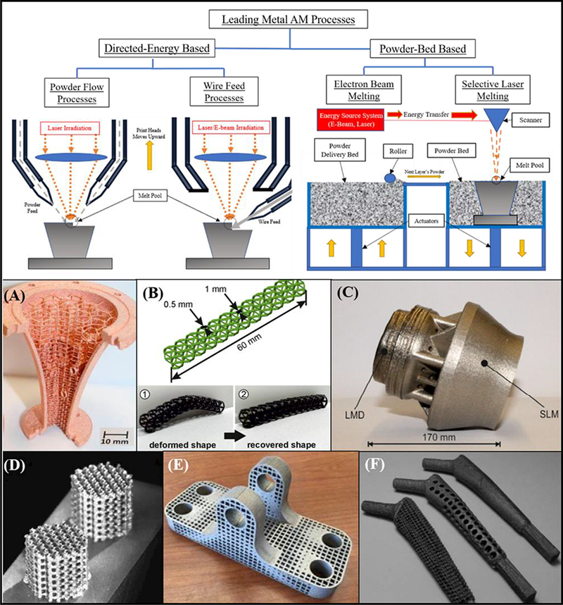
Classification of additive manufacturing processes and relevant applications. Powder bed fusion (PBF) and directed-energy-deposition (DED) are the two most widely-employed techniques for printing functional metal components. (A) Pure-Copper component manufactured via EBM with internal core structure [127] (B) Porous Nickel-Titanium shape-memory structure enabled via SLM [128] (C) LMD (or DED) repair of SLM-based Inconel 718 fuel burner [39] (D) Porous Ti6Al4V components enabled via SLM technique [129] (E) Structurally-optimized titanium-alloy component enabled via SLM [122] (F) Titanium hip stems manufactured via EBM [130].
Figure 2:
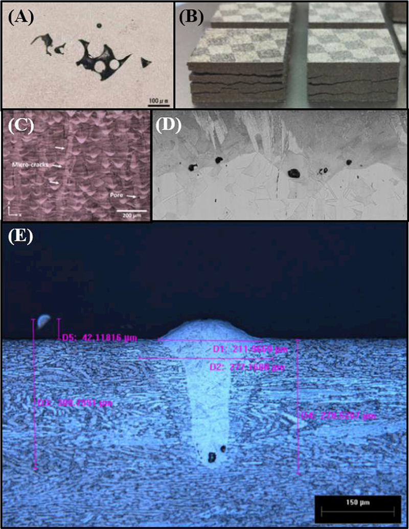
Common defects and failures during metal-AM processing. (A) Pores in EBM Ti6Al4V prior to hot isostatic pressing [41] (B) Cracking and delamination in SLM M2-High Speed Steel [131](C) Microcrack formation and pores induced in SLM Hastelloy X, a Ni-based superalloy [132](D) Pores induced from keyhole laser effect in PBF SS316 stainless steel [44]. (E) Keyhole formation in laser processing of Ti6Al4V [45].
Figure 3:
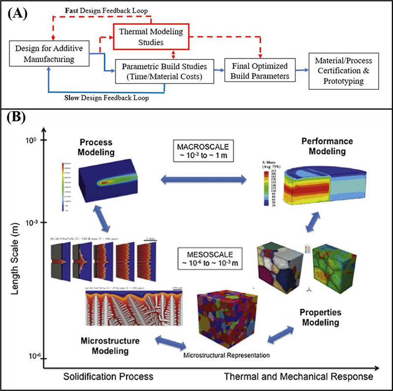
Schematics of the role of thermomechanical modeling in the manufacturing simulation and parameter optimization process. (A) Block diagram describing the process of parameter optimization for a specific application. (B) A proposed integrated approach to model the thermomechanical response and resulting properties of additively manufactured components on multiple scales [16].
Table 1:
Selected thermomechanical modeling literature, the authors’ overall strategy, and major outcomes.
| Process | Ref | Material | Energy Source | Element Scheme | Analysis | Major Outcomes |
|---|---|---|---|---|---|---|
| DED Powder Feed | [70] | Ti6Al4V | Ellipsoidal | Hybrid | 3D-Uncoupled, Pan Computing | Incorporating forced convection boundary conditions in the model improves temperature and corresponding residual stress estimates. |
| [64] | Ti6Al4V | Ellipsoidal | Quiet | 3D-Coupled, Not Listed | When printing on cantilevered plate for model verification, plate will tend to bend upwards. | |
| [57] | Inconel 718 + Ti6Al4V | Gaussian | Not Specified | 3D-Uncoupled, ABAQUS | For printing tall structures, reducing the layer thickness can increase distortion, while simultaneously decreasing residual stresses. | |
| DED Wire Feed | [76,77] | Mild Steel Wire | Gaussian | Inactive | 3D-Coupled, ABAQUS | Residual stress across a line of deposit is uniform with low affect from previous layers’ stress profile. |
| [123] | Steel Wire | Ellipsoidal | Quiet | 3D-Coupled, MSC-Marc | Final deposition path can have significant effect on the final residual stresses | |
| [68] | Inconel 718 Wire | Uniform Source | Inactive | 3D-Coupled | Using a large-strain plasticity model can result in higher accuracy, but also increases computational cost significantly. | |
| PDF EBM | [81] | Ti6Al4V | Gaussian | None-Single Scan | 3D-Coupled, ABAQUS | Increase in bed preheat temperature as high as 50°C can reduce residual stresses by ~20%. |
| [124] | Rene 80 (Ni-based superalloy) | Gaussian | None-Single Scan | 3D-Coupled, SYSWELD | Yield stresses were easily achieved after heat source passing. | |
| [84] | Inconel 718 | Effective (Temp-Driven) | Inactive | 3D-Uncoupled, ABAQUS | Preheating substrate prior to printing will reduce the magnitude of the residual stresses developed. | |
| PBF SLM | [65] | AlSi10Mg | Gaussian | Hybrid | 3D-Uncoupled, ABAQUS | Relatively long laser exposure time (slower scan speeds) will tend to induce a much larger residual stress field. |
| [73] | Stainless Steel 316 | Gaussian | Inactive | 3D-Indirectly Coupled-FE ANSYS | Residual stress calculation is reduced at high temperature when temperature-dependent thermophysical properties are accounted for. | |
| [82] | Ti6Al4V | Gaussian | Inactive | 3D-Coupled, MSC-Marc | No significant variation in residual stresses among different “square pattern” scan strategies, but significant variation in directional stresses. | |
| [125] | Inconel 718 | Double Ellipsoidal | Quiet | Thermal FE-Only Pan Computing | Assuming powder layer is insulator can significantly overpredict temperatures in component. | |
| [62] | Inconel 718 | Ellipsoidal | Hybrid | 3D-Weakly Coupled Pan Computing | Rotating scan patterns can homogenize residual stress fields. | |
| [126] | Fe-based | Gaussian | Inactive | 3D-Coupled ABAQUS | Equivalent heat source method used from single-layer simulated temperature field, reduced computational cost and maintained accuracy. | |
| [71] | Inconel 718 | Gaussian | Quiet | 3-D Coupled, ABAQUS | Rotating 45° scan patterns produce the lowest planar stresses and deformation when compared with other scanning strategies |
3. Modeling and Simulation of Metal-based Additive Manufacturing: Fundamentals
The fundamentals of thermomechanical modeling of metal-AM stem directly from early works on welding from both Rosenthal (1946) and Goldak (1983), who proposed fundamental relations for welding that describe the interaction between the build substrate, filler material, and energy source [53,54]. In general, modeling schemes are typically constructed based on the desired scale, and then reductions based on engineering judgment are made to eliminate negligible effects and increase computational efficiency. The importance of specific parameters and modeling strategies varies from technique to technique, but core aspects such as energy source and heat transfer, material addition, and residual stress, are present in modeling all metal-AM processes. A modeling consideration diagram is illustrated in Figure 4, highlighting the main choices researchers have made based on the desired model output. Table 1 outlines selected modeling literature for the different processes, strategies that were employed to model the process, and the outcomes that were achieved.
Figure 4:
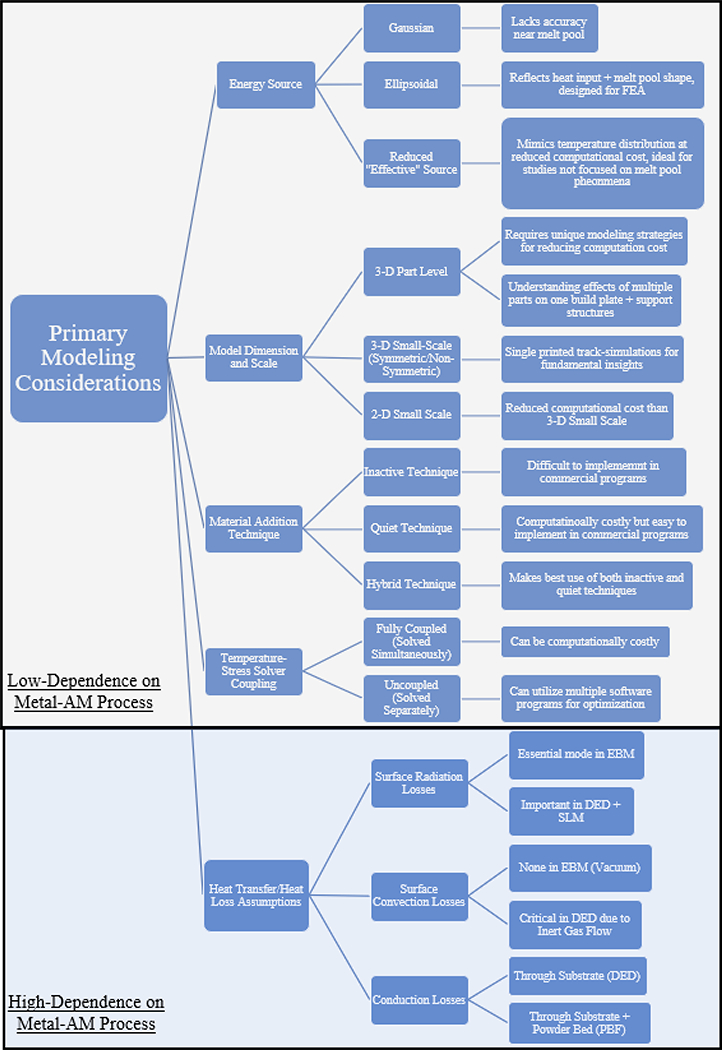
Thermomechanical modeling outline illustrating the main choices associated with creating a thermal model of AM.
3.1. General Modeling Outline and Structure
All metal-AM processes discussed herein require treatment for all three modes of heat transfer, as well as strategies for reducing computation time. These modes include radiation from the heat source and combined radiation-convection across the surface of the printed component, as well as conduction through the printed material and surroundings (see Figure 5). In most cases, including all three modes results in a model that is computationally costly, so reduction strategies must be used to narrow both the scope and model size. One technique employed by Vasinonta et al. (2007) and Foteinopoulos et al. (2018) is to create a small-scale, reduced 2-D model as opposed to a full-scale 3-D part simulation, and focus purely on the heat transfer phenomena [55,56]. The main advantage of this strategy is the reduced computational domain and corresponding solution time, but the drawback is the assumption that out of plane heat transfer and distortion are negligible, which decreases model fidelity when working with large components and complex geometries. Because of this, 2D simulation will not provide the insight required for building large-scale functional components [51], but highlights a strategy that has been employed effectively to model the process. Even in 3D simulations, however, researchers sometimes take advantage of the fact that the energy source will be symmetric along the build direction, and they reduce their computational domain to one half of the actual build size on each layer for single-track simulations [57]. Most employ the finite element (FE), finite-difference (FD), or finite-volume (FV) method for modeling the cyclic heat transfer and/or molten metal flow. A simplified model is shown in Figure 6A, whereby, a mesh of elements is shown on the build substrate as well as the area where the heat source will be activated [58]. For an extended discussion of the fundamentals of the finite element method, readers are referred to texts from K. Bathe (1997) and D. Burnett (1987) [59,60]. Most researchers employ commercial programs to evaluate the temperature profiles and residual stress using these methods, as shown in Table 1, but others have developed their own programs to customize the modeling process. Foteinopoulos et al. (2018) has outlined a 2D modeling procedure that highlights some of the key aspects of writing a numerical procedure for calculating temperature profiles and residual stress [55]. Although it employs a finite difference approach (FD) using rectangular-based elements, the general programming outline is like the finite element (FE) approach and provides insight into the key aspects of the process (see Figure 7a). Following this programming structure, material properties and process parameters are first input into the model, whereby the transient solver properties are determined (time increment, mesh density i.e. Δx & Δz). In the first time-increment, heat transfer governing equations are applied to each of the nodes and solved simultaneously to estimate the temperatures of the first time-step along the component. This process is repeated until the final nodes are heated on each layer. At this point, the program simulates a new layer of powder by increasing the distance between the bottom nodes a value of Δ𝑧 from the base of the domain, and this general process is repeated until the final height is reached. Extended discussion on the choice of boundary conditions and other numerical parameters shown in Figure 7b can be found in ref. [55]. While this model is indicative of the general approach to creating a thermal model of the additive process, it does not include radiation and any effects from phase change on the surface of the printed component, which may lead to errors when calculating the final stress profiles, highlighting a drawback for developing internal programs to model the complex phenomena inherent in additive processes.
Figure 5:
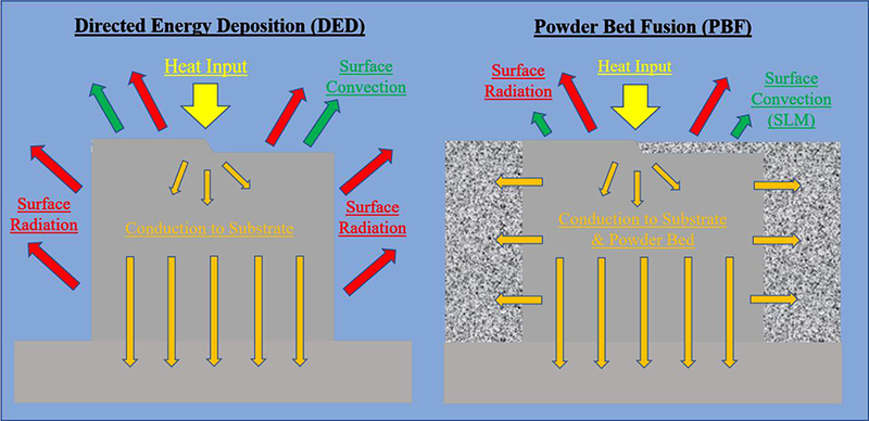
Dominant heat transfer modes in DED and PBF.
Figure 6:
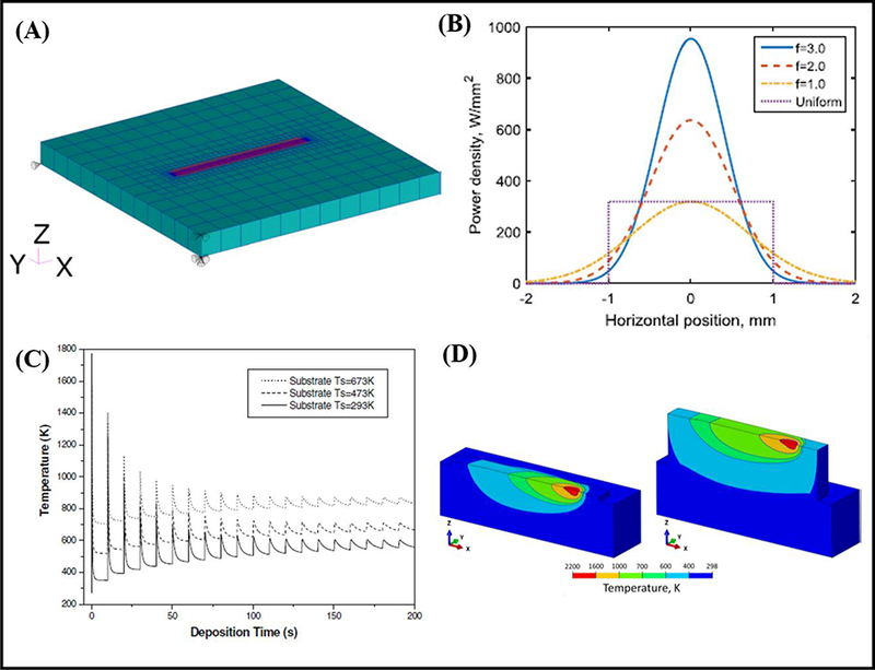
Examples of thermomechanical modeling fundamentals. (A) A general mesh around the build substrate and the area where the heat source will be applied [58]. (B) A Gaussian distribution showing the increase in focus of the distribution for higher values of 𝑓 [1]. (C) A typical temporal diagram [69]. (D) Distribution of heat within a printed component on the first and third layers. Adapted from [57].
Figure 7:
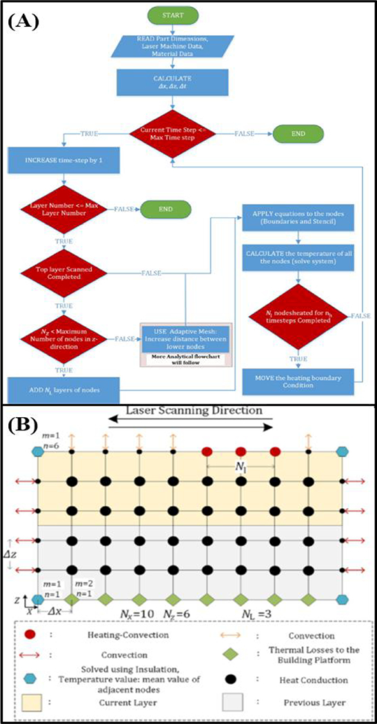
General programming outline for a 2D, uncoupled-finite difference (FD) numerical analysis scheme for predicting temperatures while a component is printed. (A) Programming block diagram illustrating the logic structure that governs the numerical solver. (B) The computational domain on which the logic structure in (A) applies, where a rectangular mesh is employed. Both images adapted from [55].
3.2. Energy Source and Heat Transfer Modes
Energy sources are traditionally modeled in the form of a Gaussian distribution (see Figure 6B), whereby the energy input is highest at the center of the beam, and decreases to zero towards the outer diameter of the spot, within a range that is dependent on the energy source characteristics and the interactions with the feedstock material [1]. Because of this, these heat input models generally follow an input equation dependent on the distance from the center of the beam, r:
| (1) |
where Qtotal is the total power flux (power per unit area) of the heat source, 𝑓 is a distribution or density factor of the heat source, 𝜂 is the laser heating efficiency, and rb is the radius of the heat source. This relation is often adapted to work in cartesian coordinates via a simple coordinate transformation dependent on the choice of reference frame and dimension of the model (2D vs. 3D). From this expression, it is evident that the input power drops exponentially from the center of the heat source, and with larger rb, there is a lower power density at every location (see Figure 6B). The Gaussian relation directly affects temperatures near the surface of the component, conduction through the component and to the baseplate, as well as the residual stresses that are formed within the component over time. Other heat source models can be found in the literature, such as ellipsoidal [61,62], which is used to mimic the temporal distribution into the component (as determined experimentally from a typical melt pool), which removes the requirement to model a heat source in detail, significantly reducing overall computational cost [63]. Once the energy source begins to interact with the feedstock material, the heat produced is either absorbed by the feedstock or reflected into the build chamber. The heat transferred into the feedstock induces a combined conduction and phase change heat transfer process (solid to liquid) to form a melt pool which is then rapidly solidified. Among different approaches, energy absorption can be fully accounted for in the efficiency term 𝜂, where the material absorbance and laser efficiency are lumped together. E. Yang et al. (2016) set this value to 45% for DED of Ti6A14V [64]. Mukherjee et al. (2017) incorporated a second absorptivity term to represent the absorption of laser energy by the previously deposited layer, adding an additional level of detail that is typically ignored within most models [57]. For powder-bed processes, the laser efficiency can also be related to the height of the powder bed and factors such as powder packing density, temperature, operating environment, etc., that can affect the overall absorptivity and conductivity of the powder bed [65,66]. In addition, to model DED-wire based processes, an alternative method involves breaking up the heat source into two components (one to heat the wire, and one to heat the substrate) to model the difference in the laser-materials interactions of DED-wire based from both DED-powder based and PBF methods [67,68]. This method takes into consideration the speed of the wire feed, and for arc-based processes considers the electric current and operating voltage of the arc. Once the underlying energy source-material interaction is established, all thermomechanical models consider a small control volume near the surface of the printed component for balancing the energy input with the substrate and deposited material. The transient energy balance results in the governing equation for a cartesian 2D-coordinate system (x and y directions are in plane with the heat source) centered on the build substrate:
| (2) |
Where 𝜌, C𝑝, and k are material properties that fluctuate significantly throughout the printing process and are invariably modeled as temperature dependent to accurately reflect such behavior. The left-hand side of the equation represents the accumulation of heat at the printed surface during the additive manufacturing process, resulting from the difference of volumetric heating and conduction loss terms in the x and y directions. This results in a temperature increase at the surface that is eventually reduced through heat loss once the energy source begins scanning a different area (i.e. where Qinput correspondingly decreases). Note that for simplicity, enthalpy of formation for phase change is neglected in this equation. The solution, i.e., temperature profile, for one point in a component will follow transient temperature (temporal) curves as outlined in Figure 6C [69]. Typical temporal distributions across a component are illustrated in Figure 6D, where red corresponds to high-temperature, and dark-blue to low temperature. On the boundary of the model, a combination of convection and radiation heat flux boundary conditions are applied to balance heat loss to the environment with the heat conducted into the printed material. The convection and radiation heat flux loss expressions are outlined as such:
| (3) |
| (4) |
Where h is the convection coefficient across the surface of the printed component, Tsurface is the component surface temperature, Tenvironment is the build chamber temperature, T∞ is the temperature of the surface by which the printed component will exchange radiative heat transfer (typically the build chamber walls and taken as room temperature), 𝜎 is the Stefan-Boltzmann constant, and 𝜖 is the printed surface emissivity, whose values can be found throughout the literature. Because EBM is done in vacuum, the convection heat loss boundary condition is not considered in analyses of its process, only surface radiation. In both SLM and DED-based processes, however, convection can play a significant role in accurately modeling heat loss to the environment. For DED, this is due to the forced flow of inert carrier gas across the surface of the printed material, which significantly increases heat transfer through convection and reduces overall surface temperatures. J. Hiegel et al. (2015) demonstrated this significance by running model cases with varying values and expressions for ℎ, observing a decrease in model error from 15.4% to 2.4% by incorporating experimentally-determined values of h (forced convection ) in comparison to lower values (free convection ) [70]. The free convection value is commonly incorporated for SLM processes to account for the inert gas environment such as in work from Cheng et al. (2016) [71]. For PBF processes, an additional conduction surface boundary condition consideration is for the un-melted powder bed particles surrounding the built structure. Some authors have neglected this condition to reduce computation time (by assuming an insulated outer surface), but Denlinger et al. (2016) demonstrated that not including it can lead to 30% higher temperatures compared to experimental values, and even higher for larger components, suggesting that accommodation of this condition is critical for modeling additive processes for functional metal components [72]. Furthermore, because the radiation boundary condition is nonlinear in temperature, it is sometimes neglected in models to increase computational efficiency with the assumption that the dominant mode of heat loss is through conduction to the substrate [73,74]. While this assumption may decrease computation time for internally-developed programs that don’t have robust radiation modeling algorithms, it will also have the effect of increasing the surface and bulk temperatures, which may lead to significant model error, particularly for complex geometries and larger components.
3.3. Material Deposition and Computational-Domain Growth
One of the most diversely-addressed aspects of metal-AM modeling is the treatment of an expanding computational domain as a part is printed. Most commercial finite element programs are designed to operate with a fixed geometry, in addition to being able to perform mesh-refinement. The challenge with additive processes is that the domain is continually growing, and modeling simple scans without an increase in domain will not provide enough insight for printing large and/or complex components. This has motivated researchers to develop their own programs and/or write subroutines in commercial FEA codes. The two most common methods of modeling material addition involve the use of “quiet” and “inactive” element activation (see Figure 8) [75]. In the “quiet” technique, the entire part is computationally present from the beginning of the process, however, elements’ thermal properties are significantly lowered until the topmost printed surface reaches the height of the element of interest. By decreasing the thermal properties of yet-to-exist elements, they have no thermomechanical effect on the rest of the model [61]. This has been implemented successfully by Denlinger et al. (2016), Zhao et al. (2012), and Yang et al. (2016) to model both DED and PBF processes using commercial programs, because the technique does not require a domain to be built during the simulation procedure, only a condition that activates the thermal properties of elements nearby to the heat source as it builds a structure. As an example, one common technique is to activate a top-layer element’s properties when its location lies within the ~90% range of the Gaussian distribution. In other words, when an element is within the outer 5% of the scanning heat flux, it is considered solid. A unique variant of this technique developed by Foteinopoulos et. al. (2018), simply increases the distance between the bottommost nodes on each successive layer, allowing for an increase in the computational domain without having to renumber nodes and increase computation time [55]. Alternatively, in the inactive-activation technique, elements are added as a layer is finished building, and the entire computational domain resets to accommodate additional elements. While this technique makes the most physical sense, it is challenging to implement in commercial FE codes as elements must be renumbered after each layer, significantly increasing computational cost and motivating the use of internally-developed codes and programs. This technique has been successfully employed to model both DED and PBF processes by Ding (2011, 2014), Li et al. (2016), and Prabhakar et al. (2017) [76,77]. A hybrid strategy employed by Michaleris (2014) has shown reduced computation time by combining both modeling strategies, whereby, elements higher in the build are set as inactive, and the following layer is set to “quiet,” then activated when the laser comes into contact with the element [78]. This technique is similarly referred to as “life and death” element activation by Wang et al. (2008) who studied thermal phenomena in welding [79].
Figure 8:
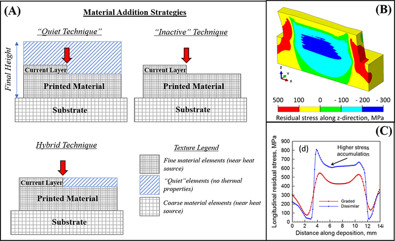
Strategies and outputs of thermomechanical models. (A) Material addition modeling strategies employed by various authors. (B) Stress distributions in a printed structure after the final layer has been printed [57]. (C) Residual stress profile along deposition path of a multi-material structure [133].
3.4. Residual Stress
For thermomechanical models of metal-AM, the end goal is to quantify the residual stress and/or distortion that is developed during printing, and authors have chosen to model this using a combination of elastic and plastic stress models based on temperature cycling. Residual stress primarily stems from the high thermal gradients and cooling rates that are inherent in the process, and influences the printed material’s tendency to expand and contract due to temperature change, affecting the bonding forces and corresponding stresses between the printed material, substrate, and/or other printed layers. Depending on the quality of the build parameters and the feedstock material properties, thermal expansion/contraction can result in delamination from the substrate and/or subsequent layers, wherever the bonding is weakest. A fundamental explanation of this phenomenon is described in refs. [1,80], which fundamentally shows that plastic strain plays a significant role in the metal-AM process, and indicates why authors typically choose to incorporate elastic-plastic theory into their thermomechanical models for residual stress prediction. Heigel et al. (2015) and Yang et al. (2016) both used a perfect plasticity model for DED, and Heigel et al. also incorporated effects from annealing due to reaching the annealing temperature for Ti6Al4V [64,70]. Vastola et al. (2016) used an isotropic hardening model related to the absolute stress in the material developed during the EBM process [81]. Parry et al. (2016) and Li et al. (2018) additionally included effects of plastic-regime work-hardening to model SLM-based processing [73,82]. Most models predict that in front of the energy source, compressive stresses are developed, and then as the energy source passes, tensile stresses begin to develop, verified by the simplified analysis referred to in the beginning of this section [1]. The stress in the build direction is predominantly recognized as the source of cracking and distortion behavior, and the stress in the build direction is responsible for delamination from the substrate (see Figure 8B) [57]. The main results from these models (and others displayed in Table 1), show that residual stresses can be decreased through manipulation of different processing factors. One of the main strategies mentioned in the literature is preheating the baseplate and/or powder bed before depositing or melting the first layer of material. Vastola et al. (2016) calculated that a 50°C increase in the powder bed temperature in EBM showed a decrease of 20% in residual stresses, and this suggestion was similarly proposed by Prabhakar et al. (2015) [83,84]. This strategy greatly reduces the thermal gradients and subsequent thermal stresses that are incumbent during processing. Additionally, varying scan patterns has been shown to play a role in the directional dependence of final stresses in the printed component as well as the overall magnitude of the residual stress [82,85,86]. Denlinger et al. (2017) proposed that reduced residual stresses were exhibited due to the rotating nature of the scanning strategy, and the homogenization of the stress field [86]. Similarly, Cheng et al. (2016) concluded that out of various line, “island,” and “snake” SLM-processing strategies, the lowest stresses in the build direction and out-of-plane distortion occurred with a 45° alternating scanning strategy, as similar stress fields were developed in both the X and Y directions on subsequent layers [71]. These models highlight the fact that thermal modeling has the potential to aid the design process for engineers by providing fundamental insights into the thermomechanical behavior of the materials as they are being printed, and suggest strategies for mitigating defects and delamination inherent in the parameter optimization process.
4. Experiment-Based Model Verification and Validation Techniques
Model verification ensures that the model runs as designed from the provided inputs and can be accurately compared to a benchmark solution provided in the literature, or first-principles analysis based on fundamental knowledge gained from other models or welding simulations. Model validation involves the use of experimentation to quantitatively ensure that the model accurately represents the physics of the problem [87]. Validation of both residual stress and temperature becomes a formidable challenge for investigators due to the inability to effectively incorporate physical measurement equipment on printed components, in addition to capturing thermal phenomena that occurs on small time and length scales. Nevertheless, researchers have utilized various techniques to evaluate the accuracy of their models. One common technique involves the use of a specially-mounted build substrate with a combination of thermocouples, displacement sensors, and strain gauges to monitor temperature, residual stress, and substrate deflection due to the thermal contraction and expansion during processing (see Figs 9A & 9B). In most experiments, the substrate will tend to deflect upwards due to the compressive stresses in the topmost section of the substrate, and this provides researchers a metric for comparing model deflection results to those of experiment. This specific method is accomplished by modeling the temperature, deflection, and residual stress occurring during the printing process with both the printed component and the cantilevered substrate in the computational domain, and then experimentally monitoring the response of the substrate. A simple structure is often chosen to be printed to decrease computation time for the model, and minimize error associated with predicting heat transfer in complex geometries. Thermocouples are typically attached to the substrate near the printed structure to minimize error. For validation, the results of both the thermal model and the experiment are superimposed on a graph, and comparisons are drawn (as shown in Figure 9C). Lia et al. (2018) uniquely embedded a thermocouple within the printed structure to monitor temperature (see Figure 9D) [88]. To quantify the model error for temperature, a node in the thermal model that is nearest to the actual thermocouple location is chosen, and the temperatures at each time point for the model are compared to the actual thermocouple reading. Within experimental investigations, Yang et al. (2016) measured as high as 1.2mm of deflection at the furthest point from the constrained substrate end when printing Ti6Al4V [64]. Using a similar setup, Heigel et al. (2015) demonstrated that the deflection direction is dependent on which direction the energy source is traveling (towards the free end or away from the free end) [70]. It was shown that when the laser was moving away from the free end, compressive stresses were developed that increased the tendency for the substrate to bend upwards. The temperatures and residual stress measurements were in strong agreement with the models (11% error for temperature, no error reported for residual stress), highlighting the efficacy of this technique. While the investigations shown in Figure 9 show techniques for DED, the same techniques have been applied to PBF techniques [89]. Other temperature measurement techniques for both investigating the thermal phenomena and verifying/validating thermal models have been investigated such as infrared thermography and pyrometry [90–93], which have equally shown strong agreement between experiment and modeling.
Figure 9:
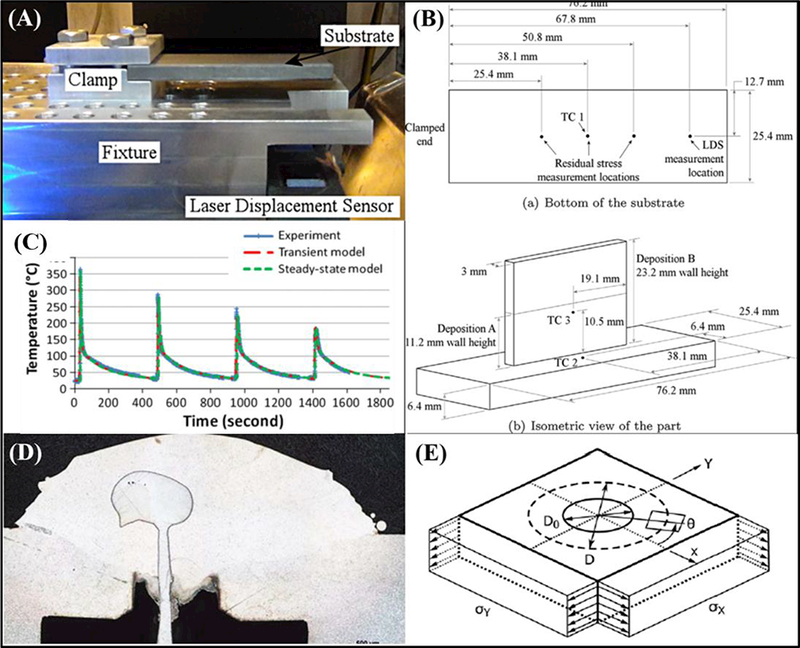
Model validation experimental setups and design. (A) Thermo-mechanical validation station for DED of Ti6Al4V [70]. (B) Thermocouple and strain gauge locations for the setup in (A) [70]. (C) Typical temporal (temperature) curves illustrating a comparison between model and experimental data [76]. (D) Micrograph of an embedded Alumina thermocouple within a track of printed material, measuring temperatures during processing [88]. (E) Schematic of the hole drilling method with the resultant residual stresses shown [94].
Various secondary techniques have been investigated for model validation of the metal-AM process by testing the as-built structure after printing. These techniques, namely, the hole-drilling technique and diffractometry, borrow concepts from non-destructive welding and joint-evaluation. These techniques are established and well-understood, but are typically only available after a component is built and are challenging to accurately compare to thermomechanical simulations. The hole drilling method involves instrumentation of the component with strain gauges in a rosette fashion, drilling a hole on the same plane as the strain gauges, and then measuring the stress relaxation induced by the hole formation (see Figure 9E) [94]. Denlinger et al. (2016) used this technique as a secondary model validation to SLM processing of Ti6A14V and Inconel 625, with limited accuracy [95]. While the setup is straightforward for this measurement, it is typically regarded as having accuracy within ±50 MPa and has been shown to be fairly unreliable in certain situations, and only applicable to near-surface stresses [96]. Elsewhere, neutron diffraction has been utilized to estimate the residual stresses in a similar manner to hole drilling, i.e., after processing [97,98]. Wang et al. (2017) demonstrated the use of this technique and the challenges associated with specific materials and their sensitivities to diffraction when in the as-processed vs. heat treated condition [99]. It is envisioned that these techniques will be scaled to work with larger geometries and provide feedback to models and the efficacy of assumptions made during the modeling process.
5. Emerging Metal-AM Applications for Modeling and Simulation
While there are review articles that provide extensive discussion on new applications and advances throughout additive manufacturing [1,9,100], this section aims to focus on the major areas where thermal modeling is envisioned to play a vital role in providing manufacturers feedback on their application-optimized designs and aid the parameter optimization process for functional metal components.
5.1. Multi-Material Additive Manufacturing
Multi-material AM is a technique that has received significant attention for its ability to create structures with multiple and/or varying properties and compositions in one or more dimensions that are challenging, or nearly impossible to make with other manufacturing techniques [101]. For metals, this process generally falls into two categories: printing premixed compositions into a functional component, or printing functionally graded components, whereby, one metal is printed on top of another through a designed joint or compositional gradient between the materials. Functionally graded components have received significant attention for their ability to maintain properties that are specific to an area of a component. These types of structures are typically manufactured from multi-step methods such as plasma/chemical vapor deposition, special casting processes, or explosive bonding, but additive allows for the precise control of geometry during processing [102–105]. Both of these strategies have been investigated using directed-energy-deposition (DED) due to the ease in changing feedstock compositions, but they have also been accomplished via powder-bed techniques with more required steps for changing feedstocks when printing one end of a component on top of another, or providing a gradation from one material to another. The main advantage of this technique is its ability to enable environment or application-specific material design, whereby a component may have a specific material in a region that sees high-temperature, oxidative, or structural environments, and a different material in the rest of the component where there may be less-demanding conditions. In many applications, this concept has been investigated for joining dissimilar materials and creating unique structures and components that have varying properties from one section to another. The joints and interfaces typically have smaller heat-affected-zones than welded joints, and can be accomplished in a single manufacturing step, reducing the cost and time to design welded joints as well as perform multiple setups and joining processes. Various authors have investigated the use of this technique for joining common engineering materials such as Ti6Al4V to Stainless Steel using DED [35,106], Inconel 718 to Copper Alloy using DED [107], Ti6Al4V to CoCrMo [108], and Ti6Al4V to Copper using EBM [109] (see Figure 10). These materials and structures have applications in the aerospace, biomedical, nuclear, among other industries, where the use of multiple materials in small spaces poses a formidable challenge for welding or brazing. As with any joining process, however, there are significant challenges to manufacturing these structures reliably. Some material systems work well when printed together or on top of one another, but others have formidable challenges related to thermal property mismatch, immiscibility of constituents, and formation of brittle intermetallic/ceramic phases at the interface which can cause cracking and eventually delamination, as is shown in Figure 10B. It is generally acknowledged that material systems not easily weldable or joinable are also not easily manufacturable in a multi-material AM process. These challenges are typically addressed via experimental techniques to minimize thermal gradients, such as baseplate heating and premixing prescribed compositions of each powder between the two main constituents (a compositional gradation to decrease interface thermal property mismatch). Elsewhere, thermodynamic modeling has resulted in optimal composition maps for functional gradients between materials by avoiding known brittle intermetallic phases [106]. A novel thermomechanical model proposed by Mukherjee et al. (2018) investigated the effect on residual stress and distortion of printing both direct and graded joints between 800H (Incoloy/Ni-Cr alloy) and Ti6Al4V/2.25Cr-1Mo Steel. The results demonstrated that large variations in thermomechanical properties of the constituents across temperature, as well as variations between separate materials, lead to complex states of stress and distortion in printed components. It is envisioned that such modeling efforts will be combined with sufficient experimentation to provide insight into the effect of processing parameters or feedstock constituent materials on the transient residual stress development and printability of multi-material systems (see Figure 10C).
Figure 10:
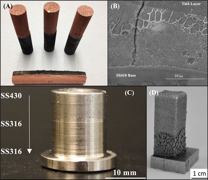
Examples of multi-material additive manufacturing. (A) Ti6Al4V cylinders with copper deposited on top, utilizing a multi-step EBM process. Adapted from [109]. (B) Stainless Steel (SS410) to Ti6Al4V direct-bonding microstructure showing crack perpendicular to interface, fabricated via DED [35]. (C) Bimetallic structure composed of magnetic Stainless Steel (SS430) and non-magnetic stainless steel (SS316), fabrication via DED [36]. (D) Stainless steel (304L) to Inconel 625 with gradient zone fabricated via DED. Adapted from [134].
5.2. Novel Materials and Alloy Design
The relative ease of changing the feedstock composition, particularly for powder-based DED methods, has given rise to alloy design and material development using additive manufacturing techniques. Traditionally, large scale methods must be used for designing and experimenting with alloying systems, however, with additive processes, one need only change the feedstock powder to experiment with the effect of different alloying elements on the resulting properties or processability of a material system. While there are inherent challenges from incomplete melting during processing, this concept has been investigated extensively to develop aluminum alloys for additive methods. These alloys have widespread use in many different industries, but inherent challenges for being manufactured via additive processes due to its high conductivity, thermal expansion rate, and solidification behavior [110–112]. Investigations by researchers to tailor the solidification behavior has resulted in aluminum alloys for additive manufacturing that contain elements such as silicon, magnesium, copper (AlSilOMg, Al-5Si-1Cu-Mg), as well as scandium (Scalmalloy®) [113,114]. In other material systems, premixing compositions of zirconium and titanium alloys has enabled researchers to design titanium alloys for biomedical and aerospace applications [115,116]. It is envisioned that modeling could play a significant role in these experimentation techniques by providing a tool that allows researchers to input the effective properties of their designed alloy to simulate the additive manufacturing process and evaluate its ability to be printed and scaled for use in large-scale components. High residual stresses or thermal gradients due to input parameters could be identified, and modifications to processing made as necessary.
5.3. Geometry and Process Optimization
Because of the impact that additive manufacturing has on enabling unique designs with geometries that aren’t possible to manufacture with traditional techniques, there has been significant investigation into environment-based geometric optimization (see Figure 11) [117], which has specifically impacted the design of lattice structures for load-bearing and mass-minimization applications [118–120]. Most CAD software typically offers packages for topology optimization based on environmental structure and/or thermal loads, whereby, the software will determine a geometry that safely withstands the prescribed environment while simultaneously minimizing a design metric such as mass or operating temperature capability [121]. These techniques, while successful in designing complex geometries, are mainly based on preliminary design and final function, and not the AM processing parameters. Due to the complex thermal phenomena that occurs during the additive manufacturing process, a particular design may not be reliably manufactured and can result in significantly anisotropic properties due to the chosen parameters [122]. Because of this, it is envisioned that thermal modeling advances will enable analysis that not only optimizes a component for a specific application, but is rooted in the chosen additive manufacturing route, guiding manufacturers and engineers when designing advanced components.
Figure 11:
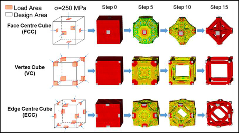
Topology optimization process for AM of metals using ABAQUS™ software package. [118].
6. Summary and Future Trend
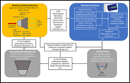
A workflow is presented in Figure 12 which outlines how simulation can be incorporated into the design-for-manufacturing process for application-optimized components. This incorporates a full-spectrum, self-improving workflow intended to utilize model reduction techniques as well as previous simulations to improve both computational efficiency and accuracy. Inputs from the overall design (geometry, features, materials, first-guess process parameters) are first uploaded to the simulation workbench (software) where a model is initiated. Previous simulation data and model reduction techniques are subsequently incorporated into the model to optimize the simulation time and accuracy. The model is then executed and the corresponding temperatures, stresses, distortion, etc. are analyzed by both the software and the design/manufacturing engineers. If the results are determined to fall within a range of acceptable tolerance, either by the software or engineers, the process parameters can then be sent to the machine for experimental validation. If the simulation results suggest otherwise, a second iteration in the mechanical design, choice of parameters, or support structures is undertaken. This step could be supplemented with topology optimization or parametric simulation studies to find an acceptable set of input parameters and geometries for the desired component, which is highly dependent on the chosen metal-AM process as well as the simplest solution to achieve acceptable results. In the rocket-nozzle example presented in Figure 12, the simulation may determine that a unique set of process parameters or compositional gradation between the two material sections is necessary. Once an acceptable set of parameters is predicted and decided upon, experimentation can commence. With the help of process monitoring techniques, the first print can provide further information on aspects such as temperature, melt pool shape, porosity, distortion, and other factors which can help validate and improve the accuracy of the future simulations while contributing to a self-improving process for the specific component. Final part properties and tolerances will additionally contribute to process improvement. These efforts will directly reduce waste material and time inherent in brute-force parameter optimization techniques and provide fundamental insights into the process that can help to develop improved standardization and design metrics for manufacturers and end-users of advanced components.
Figure 12:
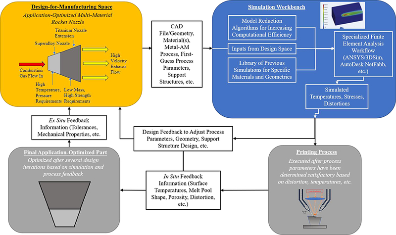
Design for manufacturing process workflow for incorporating simulation into the parameter optimization process for advanced components with variable geometry, composition, and functionality.
7. Acknowledgements
Authors acknowledge financial support from the National Science Foundation under the grant number CMMI 1538851 and the NIAMS - National Institute of Health under the grant number R01 AR067306–01A1. The content is solely the responsibility of the authors and does not necessarily represent the official views of the National Institutes of Health.
Footnotes
Publisher's Disclaimer: This is a PDF file of an unedited manuscript that has been accepted for publication. As a service to our customers we are providing this early version of the manuscript. The manuscript will undergo copyediting, typesetting, and review of the resulting proof before it is published in its final citable form. Please note that during the production process errors may be discovered which could affect the content, and all legal disclaimers that apply to the journal pertain.
8. References
- [1].DebRoy T, Wei HL, Zuback JS, Mukherjee T, Elmer JW, Milewski JO, Beese AM, Wilson-Heid A, De A, Zhang W, Additive manufacturing of metallic components – Process, structure and properties, Prog. Mater. Sci 92 (2018) 112–224. doi: 10.1016/j.pmatsci.2017.10.001. [DOI] [Google Scholar]
- [2].Tofail SAM, Koumoulos EP, Bandyopadhyay A, Bose S, O’Donoghue L, Charitidis C, Additive manufacturing: Scientific and technological challenges, market uptake and opportunities, Mater. Today 0 (2017) 1–16. doi: 10.1016/j.mattod.2017.07.001. [DOI] [Google Scholar]
- [3].Gibson I, Rosen D, Stacker B, Additive Manufacturing Technologies, 2015. doi: 10.1007/978-1-4939-2113-3. [DOI] [Google Scholar]
- [4].Bandyopadhyay A, Gualtieri T, Bose S, Global Engineering and Additive Manufacturing, 2015. doi: 10.1201/b18893-2. [DOI] [Google Scholar]
- [5].Attaran M, The rise of 3-D printing: The advantages of additive manufacturing over traditional manufacturing, Bus. Horiz 60 (2017) 677–688. doi: 10.1016/j.bushor.2017.05.011. [DOI] [Google Scholar]
- [6].Frontiers of Engineering 2011, National Academies Press, Washington, D.C., 2012. doi: 10.17226/13274. [DOI] [Google Scholar]
- [7].Li C, Fu CH, Guo YB, Fang FZ, A multiscale modeling approach for fast prediction of part distortion in selective laser melting, J. Mater. Process. Technol 229 (2016) 703–712. doi: 10.1016/j.jmatprotec.2015.10.022. [DOI] [Google Scholar]
- [8].Krueger H, Standardization for Additive Manufacturing in Aerospace, Engineering. 3 (2017) 585. doi: 10.1016/J.ENG.2017.05.010. [DOI] [Google Scholar]
- [9].Frazier WE, Metal additive manufacturing: a review, J. Mater. Eng. Perform 23 (2014) 1917–1928. doi: 10.1007/s11665-014-0958-z. [DOI] [Google Scholar]
- [10].Kok Y, Tan XP, Wang P, Nai MLS, Loh NH, Liu E, Tor SB, Anisotropy and heterogeneity of microstructure and mechanical properties in metal additive manufacturing: A critical review, Mater. Des (2017). doi: 10.1016/j.matdes.2017.11.021. [DOI] [Google Scholar]
- [11].Günther J, Brenne F, Droste M, Wendler Μ, Volkova Ο, Biermann Η, Niendorf Τ, Design of novel materials for additive manufacturing - Isotropic microstructure and high defect tolerance, Sci. Rep 8 (2018). doi: 10.1038/s41598-018-19376-0. [DOI] [PMC free article] [PubMed] [Google Scholar]
- [12].Everton SK, Hirsch M, Stravroulakis P, Leach RK, Clare AT, Review of in-situ process monitoring and in-situ metrology for metal additive manufacturing, Mater. Des 95 (2016). doi: 10.1016/j.matdes.2016.01.099. [DOI] [Google Scholar]
- [13].Berumen S, Bechmann F, Lindner S, Kruth J-P, Craeghs T, Quality control of laser- and powder bed-based Additive Manufacturing (AM) technologies, Phys. Procedia 5 (2010) 617–622. doi: 10.1016/j.phpro.2010.08.089. [DOI] [Google Scholar]
- [14].Holzmond O, Li X, In situ real time defect detection of 3D printed parts, Addit. Manuf 17 (2017) 135–142. doi: 10.1016/j.addma.2017.08.003. [DOI] [Google Scholar]
- [15].Scipioni Bertoli U, Wolfer AJ, Matthews MJ, Delplanque JPR, Schoenung JM, On the limitations of Volumetric Energy Density as a design parameter for Selective Laser Melting, Mater. Des 113 (2017) 331–340. doi: 10.1016/j.matdes.2016.10.037. [DOI] [Google Scholar]
- [16].Francois MM, Sun A, King WE, Henson NJ, Tourret D, Bronkhorst CA, Carlson NN, Newman CK, Haut T, Bakosi J, Gibbs JW, Livescu V, Vander Wiel SA, Clarke AJ, Schraad MW, Blacker T, Lim H, Rodgers T, Owen S, Abdeljawad F, Madison J, Anderson AT, Fattebert JL, Ferencz RM, Hodge NE, Khairallah SA, Walton O, Modeling of additive manufacturing processes for metals: Challenges and opportunities, Curr. Opin. Solid State Mater. Sci 21 (2017) 198–206. doi: 10.1016/j.cossms.2016.12.001. [DOI] [Google Scholar]
- [17].Bikas H, Stavropoulos P, Chryssolouris G, Additive manufacturing methods and modeling approaches: A critical review, Int. J. Adv. Manuf. Technol 83 (2016) 389–405. doi: 10.1007/s00170-015-7576-2. [DOI] [Google Scholar]
- [18].Seufzer WJ, Additive Manufacturing Modeling and Simulation A Literature Review for Electron Beam Free Form Fabrication, NASA Tech. Memo (2014) 218245. [Google Scholar]
- [19].Schelmetic T, GENOA 3DP Additive Manufacturing Simulation Tool Updated to Add Metal AM, DesignNews. (2018). https://www.designnews.com/materials-assembly/genoa-3dp-additive-manufacturing-simulation-tool-updated-add-metal-am/18433371258478.
- [20].Galati M, Iuliano L, A literature review of powder-based electron beam melting focusing on numerical simulations, Addit. Manuf 19 (2018) 1–20. doi: 10.1016/j.addma.2017.11.001. [DOI] [Google Scholar]
- [21].Thompson SM, Bian L, Shamsaei N, Yadollahi A, An overview of Direct Faser Deposition for additive manufacturing; Part I: Transport phenomena, modeling and diagnostics, Addit. Manuf 8 (2015) 36–62. doi: 10.1016/j.addma.2015.07.001. [DOI] [Google Scholar]
- [22].Zeng K, Pal D, Stucker BE, A Review of Thermal Analysis Methods in Faser Sintering and Selective Laser Melting, Proc. Solid Free. Fabr. Symp (2012) 796–814. http://utwired.engr.utexas.edu/lff/symposium/proceedingsArchive/pubs/Manuscripts/2012/2012-60-Zeng.pdf%5Cnhttp://utwired.engr.utexas.edu/lff/symposium/proceedingsArchive/pubs/TableofContents/2012_TOC.cfm. [Google Scholar]
- [23].Bourell D, Pierre J, Feu M, Levy G, Rosen D, Beese AM, Clare A, CIRP Annals - Manufacturing Technology Materials for additive manufacturing, CIRP Ann. - Manuf. Technol 66 (2017) 659–681. doi: 10.1016/j.cirp.2017.05.009. [DOI] [Google Scholar]
- [24].ASTM ISO/ASTM52900–15 Standard, Terminology for Additive Manufacturing - General Principles - Terminology, (2015). doi: 10.1520/ISOASTM52900-15. [DOI] [Google Scholar]
- [25].Wang X, Xu S, Zhou S, Xu W, Leary M, Choong P, Qian M, Brandt M, Xie YM, Topological design and additive manufacturing of porous metals for bone scaffolds and orthopaedic implants: A review, Biomaterials. 83 (2016) 127–141. doi: 10.1016/j.biomaterials.2016.01.012. [DOI] [PubMed] [Google Scholar]
- [26].Bose S, Ke D, Sahasrabudhe H, Bandyopadhyay A, Additive Manufacturing of Biomaterials, Prog. Mater. Sci (2017). doi: 10.1016/j.pmatsci.2017.08.003. [DOI] [PMC free article] [PubMed] [Google Scholar]
- [27].Wang Z, Wang C, Li C, Qin Y, Zhong L, Chen B, Li Z, Liu H, Chang F, Wang J, Analysis of factors influencing bone ingrowth into three-dimensional printed porous metal scaffolds: A review, J. Alloys Compd 717 (2017) 271–285. doi: 10.1016/j.jallcom.2017.05.079. [DOI] [Google Scholar]
- [28].Tan XP, Tan YJ, Chow CSL, Tor SB, Yeong WY, Metallic powder-bed based 3D printing of cellular scaffolds for orthopaedic implants: A state-of-the-art review on manufacturing, topological design, mechanical properties and biocompatibility, Mater. Sei. Eng. C 76 (2017) 1328–1343. doi: 10.1016/j.msec.2017.02.094. [DOI] [PubMed] [Google Scholar]
- [29].Habib A, Ahsan N, Khoda B, Optimizing Material Deposition Direction for Functional Internal Architecture in Additive Manufacturing Processes, Procedia Manuf 1 (2015) 378–392. doi: 10.1016/j.promfg.2015.09.045. [DOI] [Google Scholar]
- [30].Snyder JC, Stimpson CK, Thole KA, Mongillo D, Build Direction Effects on Additively Manufactured Channels, J. Turbomach 138 (2016) 51006. doi: 10.1115/1.4032168. [DOI] [Google Scholar]
- [31].Sahasrabudhe H, Bandyopadhyay A, Laser processing of Fe based bulk amorphous alloy coating on zirconium, Surf. Coatings Technol 240 (2014) 286–292. doi: 10.1016/j.surfcoat.2013.12.043. [DOI] [Google Scholar]
- [32].Das M, Balla VK, Basu D, Manna I, Sampath Kumar TS, Bandyopadhyay A, Laser processing of in situ synthesized TiB-TiN-reinforced Ti6A14V alloy coatings, Scr. Mater 66 (2012) 578–581. doi: 10.1016/j.scriptamat.2012.01.010. [DOI] [PubMed] [Google Scholar]
- [33].Hong C, Gu D, Dai D, Gasser A, Weisheit A, Kelbassa I, Zhong M, Poprawe R, Laser metal deposition of TiC/Inconel 718 composites with tailored interfacial microstructures, Opt. Laser Technol 54 (2013) 98–109. doi: 10.1016/j.optlastec.2013.05.011. [DOI] [Google Scholar]
- [34].Gualtieri T, Bandyopadhyay A, Additive manufacturing of compositionally gradient metal-ceramic structures : Stainless steel to vanadium carbide, 139 (2018) 419–428. [Google Scholar]
- [35].Sahasrabudhe H, Harrison R, Carpenter C, Bandyopadhyay A, Stainless steel to titanium bimetallic structure using LENS(TM), Addit. Manuf 5 (2015) 1–8. doi: 10.1016/j.addma.2014.10.002. [DOI] [Google Scholar]
- [36].Heer B, Bandyopadhyay A, Compositionally graded magnetic-nonmagnetic bimetallic structure using laser engineered net shaping, Mater. Lett 216 (2018) 16–19. doi: 10.1016/j.matlet.2017.12.129. [DOI] [Google Scholar]
- [37].Hofmann DC, Kolodziejska J, Roberts S, Otis R, Dillon RP, Suh J-O, Liu Z-K, Borgonia J-P, Compositionally graded metals: A new frontier of additive manufacturing, J. Mater. Res 29 (2014) 1899–1910. doi: 10.1557/jmr.2014.208. [DOI] [Google Scholar]
- [38].Leino M, Pekkarinen J, Soukka R, The role of laser additive manufacturing methods of metals in repair, refurbishment and remanufacturing - Enabling circular economy, in: Phys. Procedia, 2016: pp. 752–760. doi: 10.1016/j.phpro.2016.08.077. [DOI] [Google Scholar]
- [39].Petrat T, Graf B, Gumenyuk A, Rethmeier M, Laser metal deposition as repair technology for a gas turbine burner made of inconel 718, in: Phys. Procedia, 2016: pp. 761–768. doi: 10.1016/j.phpro.2016.08.078. [DOI] [Google Scholar]
- [40].Kumar LJ, Nair CGK, Laser metal deposition repair applications for Inconel 718 alloy, Mater. Today Proc 4 (2017) 11068–11077. doi:https://doi.org/ 10.1016/j.matpr.2017.08.068. [DOI] [Google Scholar]
- [41].Masuo H, Tanaka Y, Morokoshi S, Yagura H, Uchida T, Yamamoto Y, Murakami Y, Effects of Defects, Surface Roughness and HIP on Fatigue Strength of Ti-6Al-4V manufactured by Additive Manufacturing, Procedia Struct. Integr 7 (2017) 19–26. doi: 10.1016/j.prostr.2017.11.055. [DOI] [Google Scholar]
- [42].Boyce BL, Salzbrenner BC, Rodelas JM, Swiler LP, Madison JD, Jared BH, Shen Y-L, Extreme-Value Statistics Reveal Rare Failure-Critical Defects in Additive Manufacturing, Adv. Eng. Mater 19 (2017) 1700102. doi: 10.1002/adem.201700102. [DOI] [Google Scholar]
- [43].Khairallah SA, Anderson AT, Rubenchik A, King WE, Laser powder-bed fusion additive manufacturing: Physics of complex melt flow and formation mechanisms of pores, spatter, and denudation zones, Acta Mater 108 (2016) 36–45. doi: 10.1016/j.actamat.2016.02.014. [DOI] [Google Scholar]
- [44].King WE, Barth HD, Castillo VM, Gallegos GF, Gibbs JW, Hahn DE, Kamath C, Rubenchik AM, Observation of keyhole-mode laser melting in laser powder-bed fusion additive manufacturing, J. Mater. Process. Technol 214 (2014) 2915–2925. doi: 10.1016/j.jmatprotec.2014.06.005. [DOI] [Google Scholar]
- [45].Teng C, Pal D, Gong H, Zeng K, Briggs K, Patil N, Stucker B, A review of defect modeling in laser material processing, Addit. Manuf 14 (2017) 137–147. doi: 10.1016/j.addma.2016.10.009. [DOI] [Google Scholar]
- [46].Simufact Additive Manufacturing with Simufact Additive, (n.d.). https://www.simufact.com/simufact-additive.
- [47].AUTODESK Netfabb: Additive Manufacturing and design software, (n.d.). https://www.autodesk.com/products/netfabb/overview.
- [48].GEONX: a GE Additive Company, (n.d.). http://www.geonx.com/index.
- [49].Gandin C-A, Modeling of solidification: Grain structures and segregations in metallic alloys, Comptes Rendus Phys 11 (2010) 216–225. doi: 10.1016/j.crhy.2010.07.010. [DOI] [Google Scholar]
- [50].Akram J, Chalavadi P, Pal D, Stucker B, Understanding grain evolution in additive manufacturing through modeling, Addit. Manuf 21 (2018) 255–268. doi: 10.1016/j.addma.2018.03.021. [DOI] [Google Scholar]
- [51].Martukanitz R, Michaleris P, Palmer TA, DebRoy T, Liu ZK, Otis R, Heo TW, Chen LQ, Toward an integrated computational system for describing the additive manufacturing process for metallic materials, Addit. Manuf 1 (2014) 52–63. doi: 10.1016/j.addma.2014.09.002. [DOI] [Google Scholar]
- [52].Lindgren LE, Lundbäck A, Fisk M, Pederson R, Andersson J, Simulation of additive manufacturing using coupled constitutive and microstructure models, Addit. Manuf 12 (2016) 144–158. doi: 10.1016/j.addma.2016.05.005. [DOI] [Google Scholar]
- [53].Rosenthal D, The Theory of Moving Sources of Heat and Its Application to Metal Treatments, Trans. Am. Soc. Mech. Eng 68 (1946) 849–866. doi: 10.4236/eng.2011.32017. [DOI] [Google Scholar]
- [54].Goldak J, Chakravarti A, Bibby M, A new finite element model for welding heat sources, Metall. Trans. B 15 (1984)299–305. doi: 10.1007/BF02667333. [DOI] [Google Scholar]
- [55].Foteinopoulos P, Papacharalampopoulos A, Stavropoulos P, On thermal modeling of Additive Manufacturing processes, CIRP J. Manuf. Sci. Technol 20 (2018) 66–83. doi: 10.1016/j.cirpj.2017.09.007. [DOI] [Google Scholar]
- [56].Vasinonta A, Beuth JL, Griffith M, Process Maps for Predicting Residual Stress and Melt Pool Size in the Laser-Based Fabrication of Thin-Walled Structures, J. Manuf. Sei. Eng 129 (2007) 101–109. [Google Scholar]
- [57].Mukherjee T, Zhang W, DebRoy T, An improved prediction of residual stresses and distortion in additive manufacturing, Comput. Mater. Sci 126 (2017) 360–372. doi: 10.1016/j.commatsci.2016.10.003. [DOI] [Google Scholar]
- [58].Irwin J, Michaleris P, A Line Heat Input Model for Additive Manufacturing, J. Manuf. Sei. Eng 138 (2016) 111004. doi: 10.1115/1.4033662. [DOI] [Google Scholar]
- [59].Burnett DS, Finite Element Analysis: From Concepts to Applications, Addison-Wesley Publishing Company, 1987. [Google Scholar]
- [60].Bathe K, Finite Element Procedures, Prentice Hall, Eaglewood Cliffs, NJ, 1996. [Google Scholar]
- [61].Michaleris P, Modeling metal deposition in heat transfer analyses of additive manufacturing processes, Finite Elem. Anal. Des 86 (2014) 51–60. doi: 10.1016/j.finel.2014.04.003. [DOI] [Google Scholar]
- [62].Denlinger ER, Gouge M, Irwin J, Michaleris P, Thermomechanical model development and in situ experimental validation of the Laser Powder-Bed Fusion process, Addit. Manuf 16 (2017) 73–80. doi: 10.1016/j.addma.2017.05.001. [DOI] [Google Scholar]
- [63].Jamshidinia M, Kong F, Kovacevic R, Numerical Modeling of Heat Distribution in the Electron Beam Melting ® of Ti-6A1–4V, J. Manuf. Sei. Eng 135 (2013) 61010. doi: 10.1115/1.4025746. [DOI] [Google Scholar]
- [64].Yang Q, Zhang P, Cheng L, Min Z, Chyu M, To AC, Finite element modeling and validation of thermomechanical behavior of Ti-6A1–4V in directed energy deposition additive manufacturing, Addit. Manuf 12(2016) 169–177. doi: 10.1016/j.addma.2016.06.012. [DOI] [Google Scholar]
- [65].Wu J, Wang L, An X, Numerical analysis of residual stress evolution of AlSi10Mg manufactured by selective laser melting, Optik (Stuttg) 137 (2017) 65–78. doi: 10.1016/j.ijleo.2017.02.060. [DOI] [Google Scholar]
- [66].Sih SS, Barlow JW, The Prediction of the Thermal Conductivity of Powders, Proc. Solid Free. Fabr. Symp (1994) 397–401. [Google Scholar]
- [67].Montevecchi F, Venturini G, Niccolo G, Scippa A, Campatelli G, Idle times selection for wire-arc-additive-manufacturing: a finite element based technique, Addit. Manuf. (n.d.). [Google Scholar]
- [68].Chiumenti M, Cervera M, Salmi A, Agelet de Saracibar C, Dialami N, Matsui K, Finite element modeling of multi-pass welding and shaped metal deposition processes, Comput. Methods Appl. Mech. Eng 199 (2010) 2343–2359. doi: 10.1016/j.cma.2010.02.018. [DOI] [Google Scholar]
- [69].Zheng B, Zhou Y, Smugeresky JE, Schoenung JM, Lavernia EJ, Thermal behavior and microstructural evolution during laser deposition with laser-engineered net shaping: Part I. Numerical calculations, Metall. Mater. Trans. A Phys. Metall. Mater. Sci 39 (2008) 2228–2236. doi: 10.1007/s11661-008-9557-7. [DOI] [Google Scholar]
- [70].Heigel JC, Michaleris P, Reutzel EW, Thermo-mechanical model development and validation of directed energy deposition additive manufacturing of Ti-6Al-4V, Addit. Manuf 5 (2015) 9–19. doi: 10.1016/j.addma.2014.10.003. [DOI] [Google Scholar]
- [71].Cheng B, Shrestha S, Chou K, Stress and deformation evaluations of scanning strategy effect in selective laser melting, Addit. Manuf 12 (2016) 240–251. doi: 10.1016/j.addma.2016.05.007. [DOI] [Google Scholar]
- [72].Denlinger ER, Jagdale V, Srinivasan GV, El-Wardany T, Michaleris P, Thermal modeling of Inconel 718 processed with powder bed fusion and experimental validation using in situ measurements, Addit. Manuf 11 (2016) 7–15. doi: 10.1016/j.addma.2016.03.003. [DOI] [Google Scholar]
- [73].Li Y, Zhou K, Tan P, Tor SB, Chua CK, Leong KF, Modeling temperature and residual stress fields in selective laser melting, Int. J. Mech. Sci 136 (2018) 24–35. doi: 10.1016/j.ijmecsci.2017.12.001. [DOI] [Google Scholar]
- [74].Roberts IA, Wang CJ, Esterlein R, Stanford M, Mynors DJ, A three-dimensional finite element analysis of the temperature field during laser melting of metal powders in additive layer manufacturing, Int. J. Mach. Tools Manuf 49 (2009) 916–923. doi: 10.1016/j.ijmachtools.2009.07.004. [DOI] [Google Scholar]
- [75].Michael Gouge PM, Thermo-Mechanical Modeling of Additive Manufacturing, Elsevier, 2018. [Google Scholar]
- [76].Ding J, Colegrove P, Mehnen J, Ganguly S, Almeida PMS, Wang F, Williams S, Thermomechanical analysis of Wire and Arc Additive Layer Manufacturing process on large multi-layer parts, Comput. Mater. Sci 50 (2011) 3315–3322. doi: 10.1016/j.commatsci.2011.06.023. [DOI] [Google Scholar]
- [77].Ding J, Colegrove P, Mehnen J, Williams S, Wang F, Almeida PS, A computationally efficient finite element model of wire and arc additive manufacture, Int. J. Adv. Manuf. Technol 70 (2014) 227–236. doi: 10.1007/s00170-013-5261-x. [DOI] [Google Scholar]
- [78].Michaleris P, Modeling metal deposition in heat transfer analyses of additive manufacturing processes, Finite Elem. Anal. Des 86 (2014) 51–60. doi: 10.1016/j.finel.2014.04.003. [DOI] [Google Scholar]
- [79].Wang YX, Zhang P, Hou ZG, Li CZ, Inherent strain method and thermal elastic-plastic analysis of welding deformation of a thin-wall beam, J. Mech 24 (2008) 301–309. doi: 10.1017/S1727719100002434. [DOI] [Google Scholar]
- [80].Masubuchi K, Analysis of welded structures, 1982. doi: 10.1016/0026-0800(82)90012-X. [DOI] [Google Scholar]
- [81].Vastola G, Zhang G, Pei QX, Zhang YW, Controlling of residual stress in additive manufacturing of Ti6Al4V by finite element modeling, Addit. Manuf 12 (2016). doi: 10.1016/j.addma.2016.05.010. [DOI] [Google Scholar]
- [82].Parry L, Ashcroft IA, Wildman RD, Understanding the effect of laser scan strategy on residual stress in selective laser melting through thermo-mechanical simulation, Addit. Manuf 12 (2016) 1–15. doi: 10.1016/j.addma.2016.05.014. [DOI] [Google Scholar]
- [83].Vastola G, Zhang G, Pei QX, Zhang YW, Controlling of residual stress in additive manufacturing of Ti6Al4V by finite element modeling, Addit. Manuf 12 (2016) 231–239. doi: 10.1016/j.addma.2016.05.010. [DOI] [Google Scholar]
- [84].Prabhakar P, Sames WJ, Dehoff R, Babu SS, Computational modeling of residual stress formation during the electron beam melting process for Inconel 718, Addit. Manuf 7 (2015) 83–91. doi: 10.1016/j.addma.2015.03.003. [DOI] [Google Scholar]
- [85].Dunbar AJ, Denlinger ER, Heigel J, Michaleris P, Guerrier P, Martukanitz R, Simpson TW, Development of experimental method for in situ distortion and temperature measurements during the laser powder bed fusion additive manufacturing process, Addit. Manuf 12 (2016) 25–30. doi: 10.1016/j.addma.2016.04.007. [DOI] [Google Scholar]
- [86].Denlinger ER, Gouge M, Irwin J, Michaleris P, Thermomechanical model development and in situ experimental validation of the Laser Powder-Bed Fusion process, Addit. Manuf 16 (2017) 73–80. doi: 10.1016/j.addma.2017.05.001. [DOI] [Google Scholar]
- [87].Abbey T, Verification vs. Validation in Relation to FEA, Digit. Eng. (n.d.). http://www.digitaleng.news/de/verification-vs-validation/ (accessed August 20, 2004). [Google Scholar]
- [88].Lia F, Park JZ, Keist JS, Joshi S, Martukanitz RP, Thermal and microstructural analysis of laser-based directed energy deposition for Ti-6Al-4V and Inconel 625 deposits, Mater. Sei. Eng. A 717 (2018) 1–10. doi: 10.1016/j.msea.2018.01.060. [DOI] [Google Scholar]
- [89].Dunbar AJ, Denlinger ER, Gouge MF, Simpson TW, Michaleris P, Comparisons of laser powder bed fusion additive manufacturing builds through experimental in situ distortion and temperature measurements, Addit. Manuf 15 (2017) 57–65. doi: 10.1016/j.addma.2017.03.003. [DOI] [Google Scholar]
- [90].Raplee J, Plotkowski A, Kirka MM, Dinwiddie R, Okello A, Dehoff RR, Babu SS, Thermographic Microstructure Monitoring in Electron Beam Additive Manufacturing, Sci. Rep 7 (2017) 1–16. doi: 10.1038/srep43554. [DOI] [PMC free article] [PubMed] [Google Scholar]
- [91].Bai X, Zhang H, Wang G, Improving prediction accuracy of thermal analysis for weld-based additive manufacturing by calibrating input parameters using IR imaging, Int. J. Adv. Manuf. Technol 69 (2013) 1087–1095. doi: 10.1007/s00170-013-5102-y. [DOI] [Google Scholar]
- [92].Krauss H, Zeugner T, Zaeh MF, Layerwise monitoring of the Selective Laser Melting process by thermography, Phys. Procedia 56 (2014) 64–71. doi: 10.1016/j.phpro.2014.08.097. [DOI] [Google Scholar]
- [93].Wang L, Felicelli SD, Craig JE, Experimental and Numerical Study of the LENS Rapid Fabrication Process, J. Manuf. Sci. Eng 131 (2009) 41019. doi: 10.1115/1.3173952. [DOI] [Google Scholar]
- [94].ASTM, Determining Residual Stresses by the Hole-Drilling Strain-Gage Method, Stand. Test Method E837–13a. i (2008) 1–16. doi: 10.1520/E0837-13A.2. [DOI] [Google Scholar]
- [95].Denlinger ER, Michaleris P, Effect of stress relaxation on distortion in additive manufacturing process modeling, Addit. Manuf 12 (2016). doi: 10.1016/j.addma.2016.06.011. [DOI] [Google Scholar]
- [96].Svantner M, Skála J, Uncertainties of the Evaluation of the Hole Drilling Residual Stress Measurement According to the ASTM E837 Standard, Appl. Mech. Mater 732 (2015) 24–27. doi: 10.4028/www.scientific.net/AMM.732.24. [DOI] [Google Scholar]
- [97].Hodge NE, Ferencz RM, Vignes RM, Experimental comparison of residual stresses for a thermomechanical model for the simulation of selective laser melting, Addit. Manuf 12 (2016) 159–168. doi: 10.1016/j.addma.2016.05.011. [DOI] [Google Scholar]
- [98].Wu AS, Brown DW, Kumar M, Gallegos GF, King WE, An Experimental Investigation into Additive Manufacturing-Induced Residual Stresses in 316L Stainless Steel, Metall. Mater. Trans. A Phys. Metall. Mater. Sci 45 (2014) 6260–6270. doi: 10.1007/s11661-014-2549-x. [DOI] [Google Scholar]
- [99].Wang Z, Denlinger E, Michaleris P, Stoica AD, Ma D, Beese AM, Residual stress mapping in Inconel 625 fabricated through additive manufacturing: Method for neutron diffraction measurements to validate thermomechanical model predictions, Mater. Des 113 (2017) 169–177. doi: 10.1016/j.matdes.2016.10.003. [DOI] [Google Scholar]
- [100].LaMonica M, Additive Manufacturing, 2013. doi: 10.1201/b19360. [DOI] [Google Scholar]
- [101].Bandyopadhyay A, Bose S, Additive Manufacturing: Future of Manufacturing in a Flat World, in: Addit. Manuf, CRC Press Taylor and Francis Group, LLC; , Boca Raton, FL, 2016. [Google Scholar]
- [102].Naebe M, Shirvanimoghaddam K, Functionally graded materials: A review of fabrication and properties, Appl. Mater. Today 5 (2016) 223–245. doi: 10.1016/j.apmt.2016.10.001. [DOI] [Google Scholar]
- [103].Gradl PR, Rapid Fabrication Techniques for liquid Rocket Channel Wall Nozzles, in: 52nd AIAA/SAE/ASEE Jt. Propuls. Conf, 2016. doi: 10.2514/6.2016-4771. [DOI] [Google Scholar]
- [104].Koizumi M, Niino M, Overview of FGM Research in Japan, MRS Bull. 20 (1995) 19–21. doi: 10.1557/S0883769400048867. [DOI] [Google Scholar]
- [105].Sobczak JJ, Drenchev L, Metallic Functionally Graded Materials: A Specific Class of Advanced Composites, J. Mater. Sci. Technol 29 (2013) 297–316. doi: 10.1016/j.jmst.2013.02.006. [DOI] [Google Scholar]
- [106].Bobbio LD, Bocklund B, Otis R, Borgonia JP, Dillon RP, Shapiro AA, McEnerney B, Liu ZK, Beese AM, Characterization of a functionally graded material of Ti-6Al-4V to 304L stainless steel with an intermediate V section, J. Alloys Compd 742 (2018) 1031–1036. doi: 10.1016/j.jallcom.2018.01.156. [DOI] [Google Scholar]
- [107].Onuike Bonny, Heer Bryan and Bandyopadhyay Amit, Additive Manufacturing of Inconel 718-Copper Alloy Bimetallic Structure Using Laser Engineered Net Shaping (LENS(TM)), Addit. Manuf 21 (2018) 133–140. doi: 10.1016/j.addma.2018.02.007. [DOI] [Google Scholar]
- [108].Vamsi Krishna B, Xue W, Bose S, Bandyopadhyay A, Functionally graded Co-Cr-Mo coating on Ti-6Al-4V alloy structures, Acta Biomater. 4 (2008) 697–706. doi: 10.1016/j.actbio.2007.10.005. [DOI] [PubMed] [Google Scholar]
- [109].Terrazas CA, Gaytan SM, Rodriguez E, Espalin D, Murr LE, Medina F, Wicker RB, Multi-material metallic structure fabrication using electron beam melting, Int. J. Adv. Manuf. Technol 71 (2014) 33–45. doi: 10.1007/s00170-013-5449-0. [DOI] [Google Scholar]
- [110].Roberts CE, Bourell D, Watt T, Cohen J, A novel processing approach for additive manufacturing of commercial aluminum alloys, Phys. Procedia 83 (2016) 909–917. doi: 10.1016/j.phpro.2016.08.095. [DOI] [Google Scholar]
- [111].Martin JH, Yahata BD, Hundley JM, Mayer JA, Schaedler TA, Pollock TM, 3D printing of high-strength aluminium alloys, Nature. 549 (2017) 365–369. doi: 10.1038/nature23894. [DOI] [PubMed] [Google Scholar]
- [112].Coniglio N, Cross CE, Initiation and growth mechanisms for weld solidification cracking, Int. Mater. Rev 58 (2013) 375–397. doi: 10.1179/1743280413Y.0000000020. [DOI] [Google Scholar]
- [113].Li J, Cheng X, Liu D, Zhang S-Q, Li Z, He B, Wang H-M, Phase evolution of a heat-treatable aluminum alloy during laser additive manufacturing, Mater. Lett 214 (2018). doi: 10.1016/j.matlet.2017.11.111. [DOI] [Google Scholar]
- [114].Schmidtke K, Palm F, Hawkins A, Emmelmann C, Process and mechanical properties: Applicability of a scandium modified Al-alloy for laser additive manufacturing, in: Phys. Procedia, 2011: pp. 369–374. doi: 10.1016/j.phpro.2011.03.047. [DOI] [Google Scholar]
- [115].Zongge Jiao JZ, Chen Ma, Jun Fu, Xu Cheng, Haibo Tang, Don Liu, The effects of Zr contents on microstructure and properties of laser additive manufactured Ti-6.5Al-3.5Mo-0.3Si-xZr alloys, J. Alloys Compd 745 (2018) 592–598. [Google Scholar]
- [116].Li GC, Li J, Tian XJ, Cheng X, He B, Wang HM, Microstructure and properties of a novel titanium alloy Ti-6Al-2V-l.5Mo-0.5Zr-0.3Si manufactured by laser additive manufacturing, Mater. Sci. Eng. A 684 (2017) 233–238. doi: 10.1016/j.msea.2016.11.084. [DOI] [Google Scholar]
- [117].Brackett D, Ashcroft I, Hague R, Topology optimization for additive manufacturing, Solid Free. Fabr. Symp (2011) 348–362. doi: 10.1017/CB09781107415324.004. [DOI] [Google Scholar]
- [118].Xiao Z, Yang Y, Xiao R, Bai Y, Song C, Wang D, Evaluation of topology-optimized lattice structures manufactured via selective laser melting, Mater. Des 143 (2018) 27–37. doi: 10.1016/j.matdes.2018.01.023. [DOI] [Google Scholar]
- [119].Wu J, Clausen A, Sigmund O, Minimum compliance topology optimization of shell-infill composites for additive manufacturing, Comput. Methods Appl. Mech. Eng 326 (2017) 358–375. doi: 10.1016/j.cma.2017.08.018. [DOI] [Google Scholar]
- [120].Panesar A, Abdi M, Hickman D, Ashcroft I, Strategies for functionally graded lattice structures derived using topology optimisation for Additive Manufacturing, Addit. Manuf Accepted (2017). doi: 10.1016/j.addma.2017.11.008. [DOI] [Google Scholar]
- [121].Saadlaoui Y, Milan JL, Rossi JM, Chabrand P, Topology optimization and additive manufacturing: Comparison of conception methods using industrial codes, J. Manuf. Syst 43 (2017) 178–186. doi: 10.1016/j.jmsy.2017.03.006. [DOI] [Google Scholar]
- [122].Zhang P, Liu J, To AC, Role of anisotropic properties on topology optimization of additive manufactured load bearing structures, Scr. Mater 135 (2017) 148–152. doi: 10.1016/j.scriptamat.2016.10.021. [DOI] [Google Scholar]
- [123].Zhao H, Zhang G, Yin Z, Wu L, Three-dimensional finite element analysis of thermal stress in single-pass multi-layer weld-based rapid prototyping, J. Mater. Process. Technol 212 (2012) 276–285. doi: 10.1016/j.jmatprotec.2011.09.012. [DOI] [Google Scholar]
- [124].Tadano S, Hino T, Nakastani Y, A modeling study of stress and strain formation induced during melting process in powder-bed electron beam melting for Ni superalloy, J. Mater. Process. Technol 257(2018) 163–169. [Google Scholar]
- [125].Denlinger ER, Jagdale V, Srinivasan GV, El-Wardany T, Michaleris P, Thermal modeling of Inconel 718 processed with powder bed fusion and experimental validation using in situ measurements, Addit. Manuf 11 (2016) 7–15. doi: 10.1016/j.addma.2016.03.003. [DOI] [Google Scholar]
- [126].Li C, Liu JF, Guo YB, Prediction of Residual Stress and Part Distortion in Selective Laser Melting, Procedia CIRP 45 (2016) 171–174. doi: 10.1016/j.procir.2016.02.058. [DOI] [Google Scholar]
- [127].Körner C, Additive manufacturing of metallic components by selective electron beam melting - A review, Int. Mater. Rev 61 (2016) 361–377. doi: 10.1080/09506608.2016.1176289. [DOI] [Google Scholar]
- [128].Haberland C, Elahinia M, Walker JM, Meier H, Frenzel J, On the development of high quality NiTi shape memory and pseudoelastic parts by additive manufacturing, Smart Mater. Struct 23 (2014). doi: 10.1088/0964-1726/23/10/104002. [DOI] [Google Scholar]
- [129].Hollander DA, Von Walter M, Wirtz T, Sellei R, Schmidt-Rohlfing B, Paar O, Erli HJ, Structural, mechanical and in vitro characterization of individually structured Ti-6Al-4V produced by direct laser forming, Biomaterials. 27 (2006) 955–963. doi: 10.1016/j.biomaterials.2005.07.041. [DOI] [PubMed] [Google Scholar]
- [130].Harrysson OLA, Cansizoglu O, Marcellin-Little DJ, Cormier DR, West HA, Direct metal fabrication of titanium implants with tailored materials and mechanical properties using electron beam melting technology, Mater. Sei. Eng. C 28 (2008) 366–373. doi: 10.1016/j.msec.2007.04.022. [DOI] [Google Scholar]
- [131].Kempen K, Vrancken B, Buls S, Thijs L, Van Humbeeck J, Kruth J-P, Selective Laser Melting of Crack-Free High Density M2 High Speed Steel Parts by Baseplate Preheating, J. Manuf. Sci. Eng 136 (2014) 61026. doi: 10.1115/1.4028513. [DOI] [Google Scholar]
- [132].Harrison NJ, Todd I, Mumtaz K, Reduction of micro-cracking in nickel superalloys processed by Selective Laser Melting: A fundamental alloy design approach, Acta Mater 94 (2015) 59–68. doi: 10.1016/j.actamat.2015.04.035. [DOI] [Google Scholar]
- [133].Mukherjee T, Zuback JS, Zhang W, DebRoy T, Residual stresses and distortion in additively manufactured compositionally graded and dissimilar joints, Comput. Mater. Sci 143 (2018) 325–337. doi: 10.1016/j.commatsci.2017.11.026. [DOI] [Google Scholar]
- [134].Carroll BE, Otis RA, Borgonia JP, Suh JO, Dillon RP, Shapiro AA, Hofmann DC, Liu ZK, Beese AM, Functionally graded material of 304L stainless steel and inconel 625 fabricated by directed energy deposition: Characterization and thermodynamic modeling, Acta Mater 108 (2016) 46–54. doi: 10.1016/j.actamat.2016.02.019. [DOI] [Google Scholar]


