

Abstract
Blood leakages and blood loss are both serious complications during dialysis therapies. According to dialysis survey reports, these events are life-threatening issues for nephrology nurses, medical staff, and patients. When venous needle dislodgement occurs, it takes only <2.5 min of reaction time for blood loss in an adult patient, resulting in mortality. As an early-warning design, a wireless assistive technology using an integrated flexible sensor and virtual alarm unit was developed to detect blood leakage during dialysis therapies. The flexible sensor was designed using a screen print technique with printing electronic circuits on a plastic substrate. A self-organising algorithm was used to design a virtual alarm unit, consisting of a virtual direct current grid and a virtual alarm driver. In other words, this warning device was employed to identify the blood leakage levels via wireless fidelity wireless network in cloud computing. The feasibility was verified, and commercialisation designs can also be implemented in an embedded system.
Keywords: blood, patient treatment, biomedical electronics, diseases, telemedicine, medical signal detection, medical signal processing, embedded systems, virtual instrumentation, wireless LAN
Keywords: embedded system, cloud computing, wireless fidelity wireless network, virtual alarm driver, virtual direct current grid, self-organising algorithm, printing electronic circuits, flexible sensor, wireless assistive technology, blood loss, venous needle dislodgement, medical staff, nephrology nurses, dialysis therapy, blood leakage detection, virtual alarm unit, integrated flexible sensor, assistive technology
1. Introduction
In Taiwan, it has been reported that >78,000 patients with end-stage renal diseases and chronic kidney failures have received dialysis therapy, peritoneal dialysis, or kidney transplants, and this number is gradually increasing every year. Taiwan has the highest renal disease incidence and prevalence rate than Japan and the United States. Besides, renal disease has emerged as a global public health problem [1, 2], leading to increased medical costs. As a result, health insurance payments have increased to >30.8 billion Taiwan dollars in 2015. In addition, there has also been a raise in dialysis incidence, mortality, and clinical complications. In clinical cases, it takes only a few minutes to loose >40% of the adult blood volume with blood flow rates of 400–500 ml/min. Blood loss with a flow rate of 200–500 ml/min is usually detected after ∼20 s reaction time. Therefore, a flow rate of >200 ml/min and blood loss of >500 ml with <2.5 min of reaction time have been identified as the critical risk level for an adult patient [3, 4]. In 2012 [5], the American Nephrology Nurses’ Association venous needle dislodgement survey reports revealed that >50% of the surveyed candidates were very often, often, or occasionally concerned about blood leakage/blood loss during dialysis therapy. Hence, an assistive tool to detect blood leakage/blood loss is necessary for clinical needs.
The outcomes of the dialysis machine have been improved to prevent air in blood lines, blood clotting, dialyser reaction, roller pump failure, and blood leakage. Various alarms have been incorporated into the dialysis machine, which can warn system malfunction through pressure, blood leaks (optical sensor), bubble (air bubble sensor), pump flow, and temperature monitors. Determination of the correlations between heart pulses and arterial venous pressure variations could help in detecting blood line or venous needle dislodgement [6, 7], whereas different variations and venous pressure drop of <30 mmHg could stop the roller pump. However, pump pressure variations must be suppressed, because human pressures are easily influenced by patients’ movements, height changes, cannula sizes, blood flow rates, and blood line/vascular access during dialysis [5]. At present, assistive monitor tools such as pad sensors, optical sensors, and wetness sensors [2, 8–11] have been designed as early-warning detectors to reduce risk during dialysis therapy. These customised products such as Redsense® medical monitor (Conformite Europeene (CE) mark, Halmstad, Sweden, approved by the Food and Drug Administration (FDA)) [8, 9] and HEMOdialert™ [11] (for high-risk patients and home haemodialysis), can detect blood leakage from 0.01 to <2 ml with a reaction time of <2 s.
The product, HEMOsensor™, consists of upper and lower membrane layers, two spaced out electrodes, and electrical circuit connections. Each circuit connection or electrode is connected to a constant direct current (DC) voltage source. A blood contact with the conductor causes short circuit, and the electrical signal changes sent to the analytical circuit (HEMOdialert™, alarm unit [11]) are used to identify the blood loss or other conductive liquids. The product, Redsense®, relies on an optical sensor (infrared light) with a sensitivity of 1 ml of blood. However, it is not sensitive to clear but conductive liquids. Such as saline and is affected by dampness and temperature; hence, its application to blood leakage detection is limited. Moreover, electronic devices and infrared light source require continuous high operating power and lead transmission to transmit warning signals. Thus, they have no wireless transmission and limited operating distance. In addition, these alarm tools cannot stop the blood pump and have no friendly human–machine interface to show the warning indications. Besides, extra electronic devices with two spaced out designs may also limit the movement and dialysis setting of an already restless, stressed, and worried patient.
As the above-mentioned blood leakage detectors comprise a sensor substance, a signal processing unit, an analytical unit, and an alarm unit, which are designed in two spaced out devices, the present Letter proposes an early-warning assistive tool to detect pressure drops by using integrated flexible sensor [12, 13], wireless communication, and virtual alarm unit for blood leakage detection during dialysis therapies. In this Letter, a flexible sensor, consisting of electrodes and electrical connection circuits, was designed using screen printing technique with plastic substrates and metallic materials. As seen in Fig. 1, the virtual alarm unit was a digital analytical manner, which can automatically identify leakage or loss levels, was implemented in an embedded system or a tablet personal computer (PC) using a self-organising algorithm and Newton–Raphson method [14–16]. A sensing unit with a wireless fidelity (WiFi) wireless communication (IEEE 802.11 Standards [17]) and a wireless local area network (WLAN) mode can transmit blood/conductive liquid leakage information to a mobile device. Hence, smart mobile devices can receive the warning indications in indoor environment or haemodialysis room. Our proposed tool has various advantages including compact sensor, improved detection reliability, personalised physiological monitoring, and easy implementation of the application software in smart mobile devices. Finally, the feasibility and specification of the proposed model were validated.
Fig. 1.
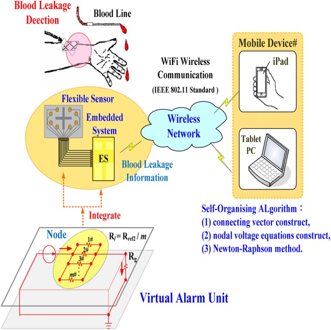
Proposed configuration of virtual alarm unit for blood leakage detection
2. Methodology
2.1. Proposed configuration of flexible sensor
Flexible sensors have simpler electronic circuits, and can be printed on plastic or polymeric substrates, offering mechanical flexibility, thinness, and light weight [12, 18]. Owing to soft, flexible, and stretchable properties, these sensors can be integrated in a mobile and wearable device on the human body. For non-invasive sensing, rehabilitations, and diagnostic applications, photodetector, temperature sensors, pressure sensors, or gas sensors are widely used in clinical needs. An advantage of the flexible sensor is that it can be placed anywhere on the patient's body, can continuously monitor an individual's health states [13], and can also achieve real-time personalised physiological monitoring without affecting the patient's current motions and dialysis setting.
A flexible printed circuit board was printed on a plastic substrate with a size of 60 × 40 mm using body-fluid, blood, and conductive liquid sensitive element with nine nodes, as seen in Fig. 2. Its function was a configuration of eight-position switch, manipulating the open-and-closed states based on blood leakage or serious blood loss. Interface conductors were connected directly to an embedded system connector [digital input (DI)] using the pull-down on mapping serial port (MSP) connectors. The MSP connectors (DI-01–DI-08) were used to measure 0.0–3.3 V signal [19], as presented in Fig. 2. For a constant voltage source, Vcd = +3.3 V, eight connecting conductors were placed as short circuit in any position. Thus, each DI had a connection from Vcd to pull-down resistor, and then 8 bit binary patterns were obtained and can be defined as
| (1) |
Fig. 2.
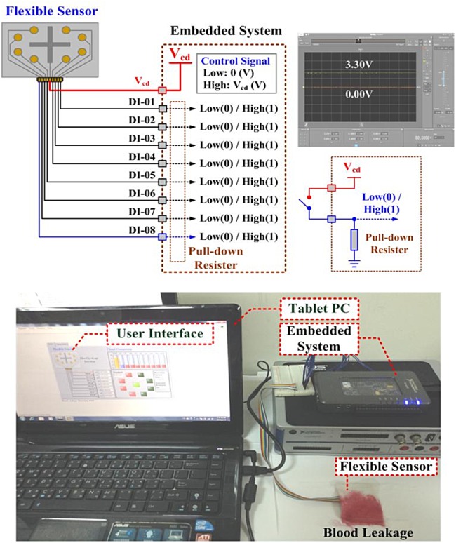
Prototype configuration of the flexible sensor
Connecting state: , which were used to control the virtual grounded resistor, Rg, in the virtual DC grid, as shown in Fig. 1.
Subsequently, we developed an application programme to transmit the connecting states from the flexible sensor to mobile appliances via synchronous serial communication. The WiFi WLAN technique [17, 20] could transmit the connecting states or upload the data/parameters for cloud computing, and was used for linking mobile devices (smart phones, personal digital assistant, or iPad) and portable computer support (laptop) by operating on 2.4 GHz industrial, science, and medical frequency bands.
2.2. Virtual alarm unit for blood leakage detection
As illustrated in Fig. 3, consider a virtual DC grid consisting of 10 nodes (n = 10) and 11 branches (b = 11), with three connecting vectors between two nodes and four grounded connecting vectors from one node to reference node. The connecting resistors are
| (2) |
where m resistors are paralleled in each connecting branch (m = 8 in this Letter), which imitate the adherent resistances on the swab. A self-organising algorithm [14–16] is used to automatically construct a ten-nodal virtual DC grid. The constant resistor Rs is the internal resistor in an injection current source IS. Resistors Rref1 and Rfef2, where Rref1 = 2 × Rfef2, are used to determine the normal output voltage V2 at node ②# using the voltage divider rule as
| (3) |
Fig. 3.
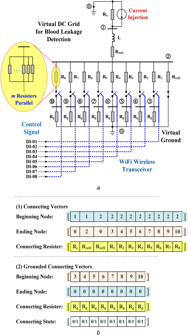
Configuration of the proposed virtual DC grid for blood leakage detection
a Virtual DC grid
b Connecting vectors for constructing the DC grid
As shown in Fig. 3b, the grounded connecting vectors were used to construct the short-circuit branches between one node and the virtual ground (grounded branch g = 8) due to blood leakage/blood loss. Constant Rg is the virtual grounded resistor, calculated as
| (4) |
When blood leakage is detected by the sensing unit, the control signal in connecting state vector will be ‘C = 1’ and the grounded branch will be connected; otherwise, ‘C = 0’.
By using the beginning–ending node vector and connecting resistor vector, the nodal numbers and connecting branch resistors, Rij, are stored in connecting vectors from beginning nodes to ending nodes, where parameters i and j are the connecting indexes. Thus, the whole virtual DC grid has the following admittance matrix [15, 16]
| (5) |
| (6) |
| (7) |
where node number n = 10, branch number b = 11, and element yik is the admittance (yii≠0) between the nodes i and k.
In the whole virtual DC grid, seen in Fig. 3a, only the current source is injected into the DC grid and the nodal voltage equations are
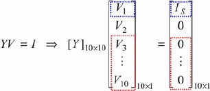 |
(8) |
| (9) |
where IS is the injection current into node ①#, Y is a symmetric matrix, Vi is the ith guess, and I = [I1, I2, …, Ii, …, In] = [IS, 0, 0, …, 0] is an n = 10 vector of function that can specify the iteration mode. The iterative procedure is terminated until the convergent condition
| (10) |
where Vi(p) is the ith component of vector V and ε is the specified tolerance level.
By using the Newton–Raphson method [15], the ith equation can be given as
| (11) |
The iteration mode uses the value of Vi(p) at iteration p to generate Vi(p + 1) as follows:
| (12) |
| (13) |
The matrix form can be represented as
 |
(14) |
Jacobian (J) matrix
| (15) |
where 10 × 10 matrix elements are the partial derivatives of the n = 10 nodal voltage equations. The inverting matrix of J, i.e. J−1 = Y−1, can be computed and then stored in the digital storage unit.
Thus, nodal voltages, V2–V10, can be calculated using Newton–Raphson method, and their grasp changes are used to identify the blood leakage, as follows:
| (16) |
| (17) |
where voltage, Vref, is the threshold value to identify the blood leakage, and state variable Sj = 1 indicates one or more nodes that have detected blood leakage events. Therefore, signal ‘1,’ as a high level (3.33 V), acts to drive a relay to trip the roller pump, as an output alarm driver, as seen in Fig. 4a [19]. Fig. 5 illustrates the overall procedure of the self-organising algorithm including (i) connecting vectors construct, (ii) nodal voltage equations construct, and (iii) Newton–Raphson method.
Fig. 4.
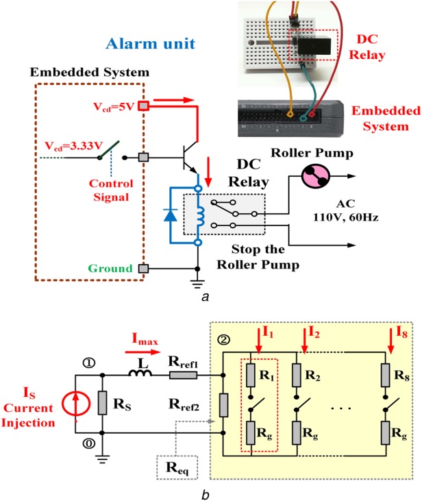
Equivalent virtual DC grid and output driver unit
a Output alarm driver for tripping the roller pump
b Equivalent virtual DC grid in a simple RL circuit
Fig. 5.
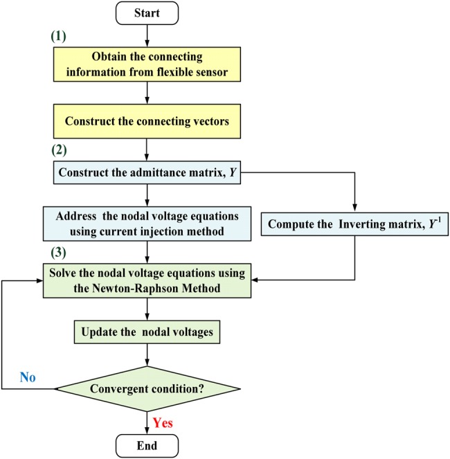
Flowchart of the self-organising algorithm
The whole DC grid can be transformed into an equivalent DC grid in a simple resistor-inductor circuit (RL) circuit using Thevenin theorem, as shown in Fig. 4b. The equivalent resistor from node 2# is
| (18) |
| (19) |
where m is the number of grounded branch. The transient response of the whole equivalent grid is [15]
| (20) |
| (21) |
For a very large time t→∞, the total injection current Imax into node ②# will monotonically increase as follows
| (22) |
where the equivalent resistor Req becomes small and the maximum injection current Imax will increase. More blood leakage or serious blood loss causes the adherent resistances to decrease. In this Letter, two grasp changes were used to qualify the level of blood leakage, and can be summarised as follows:
Nodal voltage drops: Given the reference voltage V2, the nodal voltages V3–V10 drop, while one or more sensing points in the flexible sensor detect blood leakage.
Injection current into node 2#: The maximum injection current Imax increases with the gradual decrease in the equivalent resistor, Req.
3. Experimental results
The prototype virtual alarm unit was established in an embedded system (National Instruments™ myRIO-1900, Austin, Texas, USA), as shown in Fig. 2. The self-organising algorithm including the connecting vectors construct, nodal voltage equations construct, and Newton–Raphson method, was coded in the microprocessor using a text-based programming language. The PC-based user-friendly interface or mobile device applications (iPad) was designed to display the monitoring results. The flexible sensor was designed using a screen printing technique with copper circuits printed on a plastic substrate, as shown in Fig. 6. The flexible sensor and WiFi wireless transceiver were integrated as a sensing unit to detect blood leakages. As illustrated in the connecting topology presented in Fig. 3a, the specifications of the proposed virtual alarm unit were shown in Table 1. The proposed detection model was designed using a LabVIEW graphical programming user interface (NI™ Corporation, Austin, Texas, USA) in the math-script workspace [19], and was run in a tablet PC or a mobile intelligent device.
Fig. 6.
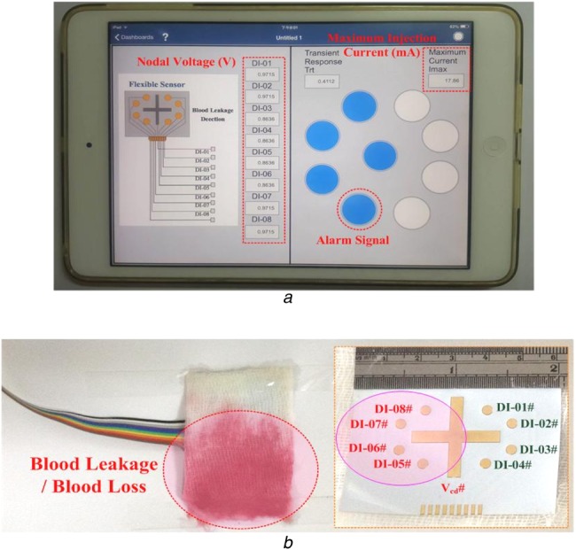
Experimental results
a Warning indications in a mobile intelligent device
b Blood leakage case study
Table 1.
Specification of the proposed virtual alarm unit
| Flexible sensor | constant voltage source | Vcd = +3.3 V, high: +3.3 V, low: 0.0 V |
| input port | MSP (port) connector, one pin for Vcd, eight pins for DI-01–DI-08, pull-down resistor: 40 kΩ | |
| wireless communication | 2.4 GHz, WiFi, WLAN mode, outdoor transmission distance: <50 m and >−80 dBm, indoor transmission distance: <30 m and >−70 dBm | |
| Virtual alarm unit | virtual injection current, A | 1.0 A |
| virtual circuit element | RS = 10 Ω, Rref1 = 500 Ω, Rref2 = 250 Ω, L = 100 H, Rref4 = 9 × Rref1, Rref3 = 1 kΩ, Rg = 250 Ω, Rl = (1/m) × 250 Ω, l = 1, 2, 3, …, 8, m = 1, 2, 3, …, 8 | |
| voltage level for identifying normal condition | virtual voltage: +3.28 V | |
| voltage level for identifying blood leakage | the range of voltage level: 3.28–0.57 V | |
| injection current for identifying blood leakage | the range of injection current: 13.15–18.51 mA |
In case of a blood leakage event, as shown in Fig. 6, blood leakage covers the nodes 5#, 6#, 7#, and 8# and causes short circuit in the four circuit connections. Subsequently, the connecting states can be detected and the signals can be transmitted to the virtual DC grid via the WiFi wireless transceiver, as C = [C1, C2, C3, C4, C5, C6, C7, C8] = [0, 0, 1, 1, 1, 1, 0, 0].
Then, the self-organising algorithm constructs the admittance matrix Y using the connecting vectors, connecting resistors, and connecting states. The square matrix (10 rows × 10 columns), Y, is a symmetric matrix, given as
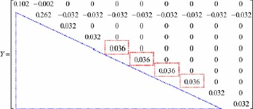 |
As shown in the red dash-line rectangle, the diagonal elements of Y matrix, y55, y66, y77, and y88, increased as the grounded branches, ②-⑤-⓪,②-⑥-⓪,②-⑦-⓪, and ②-⑧-⓪, were added to the virtual DC grid. These were the algebraic sum of the admittance connections including 1/Rg from the nodes, ⑤, ⑥, ⑦, and ⑧, to the virtual ground ⓪. The nodal voltages, V2–V10, can be calculated using the current injection method and Newton–Raphson method as
| Voltage vector, V = [V2, V3, V4, V5, V6, V7, V8, V9, V10] = [0.9715, 0.9715, 0.9715, 0.8636, 0.8636, 0.8636, 0.8636, 0.9715, 0.9715], Vmin = min(V) = 0.8636 V, Vmax = max(V) = 0.9715 V, Vref = 0.9176 V, state vector, S = [S3, S4, S5, S6, S7, S8, S9, S10]=[0, 0, 1, 1, 1, 1, 0, 0], maximum injection current, Imax = 17.79 mA. |
It took a reaction time of 0.4112 s (transient response) to reach the maximum injection current. The grasp changes in the nodal voltage can be identified using (16) and (17). As the reference nodal voltage, V2 = 0.9715 V, voltages V5–V8 <voltage V2. The state variables, S5, S6, S7, and S8, indicated ‘signal 1’ to identify the blood leakage event and drive the virtual alarm unit. This simple technique could be easily implemented in a mobile intelligent device, and the experimental results obtained via WiFi wireless connection are presented in Fig. 6a. Under normal conditions and the nodal voltage V2 = 3.28 V as the reference voltage, the drop levels from 2.06 to 0.57 V were used to separate the normal condition from blood leakage or serious blood loss events, as shown in Fig. 7a. Both the maximum injection currents and reaction time increased from 15.73 to 18.51 mA and from 0.3626 to 0.4282 ms, respectively, as seen in Fig. 7b.
Fig. 7.
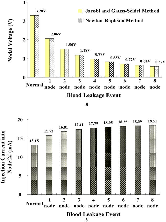
Voltage and current specification for blood leakage detection
a Nodal voltages versus blood leakage events at node 2#
b Maximum injection current into node 2#
In addition, the sensing unit with a WiFi WLAN mode could transmit the data to a mobile device in the outdoor range of <50 m and indoor range of <30 m. The received signal strength indicators were about >−80 and >−70 dBm. The experiments showed the smart mobile device (iPad) could receive the warning information which envisaged deployment conditions in the indoor environment. Therefore, the sensing unit in its communication applications was reliable in short wireless transmission distance (haemodialysis room: 20 × 30 m). The experimental results confirmed that the developed tool, combining computation, and wireless communication functionality, could detect blood leakage or serious blood loss for monitor applications during dialysis therapies. The suggested specifications of the proposed virtual alarm unit are shown in Table 1.
4. Discussion and conclusion
Both the Gauss elimination and back-substitution method and Newton–Raphson method could solve the linear simultaneous equations. The performances and computing-time requirement must be evaluated by determining the number of arithmetic operations including multiplication/division and subtraction/addition [15] as shown in Table 2. In contrast to the Gauss elimination and back-substitution method, the proposed method requires ∼<0.1100 ms for iteration computations to solve n = 10 simultaneous equations. While Newton–Raphson method can reduce the number of multiplications, divisions, and subtractions/additions, its iteration process converges in <5 iteration computes, with the specified tolerance level ε ≤ 0.01. However, the memory storage of Newton–Raphson method is slightly greater than that of Gauss elimination and back-substitution method. A fill-in with non-zero elements in the admittance matrix Y could increase the memory storage and computing-time requirements. In addition, a sparse matrix technique [15, 21] can be used to overcome the requirements of memory storage and computing time such as storing the upper triangular portion of the symmetric matrix Y or storing non-zero elements in one-dimensional vector with row and column indications stored in two index vectors. Therefore, the proposed self-organising algorithm is suggested to be superior for establishing in an embedded system.
Table 2.
Comparison of the Newton–Raphson method and Gauss elimination and back-substitution method
| Task | Method | |
|---|---|---|
| Gauss elimination and back-substitution method | Newton–Raphson method | |
| memory storage | n2 for matrix Y and n for vector I | 2 × n2 for matrices, Y and J−1, 3 × n for vectors, I, V(p + 1), V(p) |
| 440 B | 920 B | |
| multiplications | ≃n3/3 for Gauss elimination | 2 × n2 per iteration |
| ≃n2/2 for back substitution | ||
| divisions | ≃n2/2 for Gauss elimination | – |
| n for back substitution | ||
| subtractions/additions | ≃n3/3 for Gauss elimination | ≃2 × n2 per iteration |
| ≃n2/2 for back substitution | ||
| iteration process | – | <5 |
| computer time, ms | 0.4817 | <0.2200 |
(i) digital computer time for multiplications/divisions: 10−6 s; (ii) digital computer time for subtractions/additions: 10−7 s, and (iii) 4 B for each digital storage [15].
In addition, the flexible sensor was designed using a screen printing technique with plastic/elastic substrates and metallic materials. Considering the biocompatibility and electrical safety, medical electrical equipments need to be validated for safety and effectiveness before their commercialisation by the standard of International Electrotechnical Commission (IEC) 60601 series [22]. The design of the proposed monitoring sensor has reduced a large amount of electrical units including the analytical circuit and alarm unit which have been virtualised and implemented in an embedded system and intelligent mobile devices. With its feasibility that had been verified, the proposed individualised prototype tool can also enhance the priority in warning signals reading, cloud computing, and cloud storages via WiFi wireless communication for clinical applications during dialysis therapies.
5. Funding and Declaration of Interests
This work is supported in part by the Ministry of Science and Technology, Taiwan, under contract number: MOST 105-2218-E-075B-001, duration: March 1 2016–February 28 2017. The authors declare that there is no conflict of interests regarding the publication of this paper. The study doesn't involve human and animal subjects.
6 References
- 1.Hwang S.-J., Tsai J.-C., Chen H.-G.: ‘Epidemiology, impact and preventive care of chronic kidney disease in Taiwan’, Nephrology, 2010, 15, pp. 3–9 (doi: 10.1111/j.1440-1797.2010.01304.x) [DOI] [PubMed] [Google Scholar]
- 2.Chadayan A., Rasi M.D.: ‘A survey on blood leakage monitoring in hemodialysis therapy’, Int. J. Appl. Inf. Commun. Eng., 2015, 1, (11), pp. 14–16 [Google Scholar]
- 3.Polaschegg H.-D.: ‘Venous needle dislodgement: the pitfalls of venous pressure measurement and possible alternatives, a review’, J. Renal Care, 2010, 36, (1), pp. 41–48 (doi: 10.1111/j.1755-6686.2010.00142.x) [DOI] [PubMed] [Google Scholar]
- 4. American Nephrology Nurses’ Association (ANNA), 2012. Available at https://www.annanurse.org/resources/venous-needle-dislodgement .
- 5.Axley B., Speranza-Reid J., Williams H.: ‘Venous needle dislodgement in patients on hemodialysis’, Nephrol. Nursing J., 2012, 39, (6), pp. 435–445 [PubMed] [Google Scholar]
- 6.Holmer M., Sandberg F., Solem K., et al. : ‘Extracting cardiac signal from the extracorporeal pressure sensors of a hemodialysis machine’, IEEE Trans. Biomed. Eng., 2015, 62, (5), pp. 1305–1315 (doi: 10.1109/TBME.2014.2385964) [DOI] [PubMed] [Google Scholar]
- 7.Lin C.-H., Chen W.-L., Kan C.-D., et al. : ‘Detection of venous needle dislodgement during hemodialysis using fractional order shape index ratio and fuzzy color relation analysis’, IET Healthc. Technol. Lett., 2015, 2, (6), pp. 149–155 (doi: 10.1049/htl.2015.0022) [DOI] [PMC free article] [PubMed] [Google Scholar]
- 8.Chuang H.-C., Shih C.-Y., Chou C.-H., et al. : ‘The development of a blood leakage monitoring system for the applications in hemodialysis therapy’, IEEE Sens. J., 2015, 15, (3), pp. 1515–1522 (doi: 10.1109/JSEN.2014.2364302) [Google Scholar]
- 9.Hurst J.: ‘It can happen without warning: venous needle dislodgement’, Renal Bus. Today, 2009, 4, (9), pp. 18–22 [Google Scholar]
- 10.Moll B.J., Moll R.L., Anne Moll Family Trust: ‘Method and device for monitoring loss of body fluid and dislodgment of medical instrument from body’. Patent US 20050038325 A1. Available at https://www.goole.ch/patents/US200 50038325
- 11. HEMOdialertTM, 2014. Available at https://www.hemodialert.com. and www.hemodialert.com/hemodialert-hemodialysis-alarm.php .
- 12.Donati M., Vitiello N., Rossi S.M.M.D., et al. : ‘A flexible sensor technology for the distributed measurement of interaction pressure’, Sensors, 2013, 13, pp. 1021–1045 (doi: 10.3390/s130101021) [DOI] [PMC free article] [PubMed] [Google Scholar]
- 13.Gao W., Emaminejad S., Nyein H.Y., et al. : ‘Fully integrated wearable sensor arrays for multiplexed in situ perspiration analysis’, Nature, 2016, 529, pp. 509–514 (doi: 10.1038/nature16521) [DOI] [PMC free article] [PubMed] [Google Scholar]
- 14.Brown H.E.: ‘Solution of large network by matrix methods’ (Wiley, New York, 1975) [Google Scholar]
- 15.Duncan Glover J., Sarma M.: ‘Power system analysis and design’ (PWS Publishing Company, Boston: ) [Google Scholar]
- 16.Maknouninejad A., Qu Z., Lewis F.L., et al. : ‘Optimal, nonlinear, and distributed designs of droop controls for DC microgrids’, IEEE Trans. Smart Grid, 2014, 5, (5), pp. 2508–2516 (doi: 10.1109/TSG.2014.2325855) [Google Scholar]
- 17. Institute of Electrical and Electronics Engineers. IEEE Std. 802.11-2007, Wireless LAN Medium Access Control (MAC) and Physical Layer (PHY) Specifications, 12 June 2007.
- 18.Tahir R., Tahir H., McDonald-Maier K.: ‘Securing health sensing using integrated circuit metric’, Sensors, 2015, 15, pp. 26621–26642 (doi: 10.3390/s151026621) [DOI] [PMC free article] [PubMed] [Google Scholar]
- 19.Doering E.: ‘NI myRIO-project essentials guide’ (National Technology and Science Press, 2014) [Google Scholar]
- 20.Vallozzi L., Torre P.V., Hertleer C., et al. : ‘Wireless communication for firefighters using dual-polarized textile antennas integrated in their garment’, IEEE Trans. Antennas Propag., 2010, 58, (4), pp. 1357–1368 (doi: 10.1109/TAP.2010.2041168) [Google Scholar]
- 21.Stoer J., Bulirsch R.: ‘Introduction to numerical analysis’ (Springer-Verlag, Berlin, New York, 2002) [Google Scholar]
- 22. IEC 60601-1: 2005, International Standard, Medical electrical equipment – Part 1: general requirements for basic safety and essential performance.