Abstract
Purpose:
To investigate how high-permittivity materials (HPMs) can improve signal-to-noise ratio (SNR) when placed between magnetic resonance detectors and the imaged body.
Methods:
We used a simulation framework based on dyadic Green’s functions to calculate the electromagnetic field inside a uniform dielectric sphere at 7 Tesla, with and without a surrounding layer of HPM. SNR-optimizing (“ideal”) current patterns were expressed as the sum of signal-optimizing (“signal-only”) current patterns and dark mode current patterns that minimize sample noise while contributing nothing to signal. We investigated how HPM affects the shape and amplitude of these current patterns, sample noise, and array SNR.
Results:
Ideal and signal-only current patterns were identical for a central voxel. HPMs introduced a phase shift into these patterns, compensating for signal propagation delay in the HPMs. For an intermediate location within the sphere, dark mode current patterns were present and illustrated the mechanisms by which HPMs can reduce sample noise. High-amplitude signal-only current patterns were observed for HPM configurations that shield the electromagnetic field from the sample. For coil-arrays, these configurations corresponded to poor SNR in deep regions, but resulted in large SNR gains near the surface, due to enhanced fields in the vicinity of the HPM. For very high relative permittivity values, HPM thickness corresponding to even multiples of λ/4 resulted in coil SNR gains throughout the sample.
Conclusion:
HPMs affect both signal sensitivity and sample noise. Lower-amplitude signal-only optimal currents corresponded to higher array SNR performance, and could guide the design of coils integrated with HPM.
Keywords: Magnetic Resonance Imaging, ideal current patterns, SNR, ultimate intrinsic SNR, high permittivity materials
INTRODUCTION
The expected increase in signal-to-noise ratio (SNR) with static magnetic field strength (B0) has been a primary motivation for ultra-high field magnetic resonance imaging (MRI) (1,2). However, inhomogeneities of the radiofrequency (RF) magnetic field (B1), caused by wavelength effects, and asymmetries between transmit (B1+) and receive (B1–) sensitivity patterns, have made imaging at ultra-high field (B0 ≥ 7 T) particularly challenging (3,4). A recently proposed approach to reducing B1 inhomogeneity and improving coil performance is the utilization of high permittivity materials (HPMs), with relative permittivity (εr) greater than 50, placed between the RF coil and the imaged body (5–12).
According to the principle of reciprocity, the sensitivity of an RF coil to the MR signal originating at a position of interest is proportional to the pertinent circularly-polarized component (B1–) of the RF magnetic field, which would be produced at that position by exciting the coil with unit current. The intrinsic sample noise received by the same coil, meanwhile, is proportional to the square root of where E is the corresponding electric field of the excited coil as a function of position r, s is the distribution of conductivity in the body, and V is the body volume. The SNR enhancement observed in the presence of HPM has been attributed to increased signal sensitivity due to a secondary magnetic field generated by displacement currents within the HPM as per the Maxwell-Ampere law (6). The application of the Maxwell-Ampere law alone is a first-order approximation, which assumes that the E field within the HPM and sample does not change. However, according to Faraday’s law the secondary B1 field also induces an E field, and thus sample noise is also expected to increase. Therefore, it is not obvious precisely how HPMs result in a net SNR improvement.
Furthermore, the assumption that the observed SNR improvement is solely due to the secondary B1 field fails to explain why larger relative permittivity values do not consistently improve performance (13), given that displacement currents are directly proportional to relative permittivity via the Maxwell-Ampere law. In fact, it has been shown that HPM with large relative permittivities in some cases could introduce significant inhomogeneities within the imaging sample (14), or concentrate the magnetic flux within the HPM itself, preventing its propagation into the imaging sample (15).
Given this limited understanding of the behavior of HPM, heuristic approaches have been used to tailor the relative permittivity value to the geometry of the HPM pad and to a specific region of interest (ROI) within the imaging sample (11,13). One of these studies utilized numerical electromagnetic (EM) field simulations and varied the geometry and electrical properties of the HPM pads to find the optimal configuration (11). Another study used a fast analytical calculation framework based on dyadic Green’s functions (DGF) to investigate the optimal relative permittivity for a layer of HPM surrounding a homogeneous head-mimicking sphere for different field strengths and object sizes (12,13). Although an extensive search for the optimal HPM properties for a particular application could be an effective strategy, a better understanding of the effects of HPM on signal and noise could considerably reduce the number of simulations required to establish optimality, and could help to guide rational strategies for coil design.
Ideal current patterns, which are the receive current patterns associated with the ultimate intrinsic SNR (UISNR) at a voxel of interest, have been proposed as guidelines for optimal coil design (16). For example, ideal current patterns have been used to demonstrate graphically the near optimality of traditional surface and volume quadrature coils at low field strength, and to elucidate the sub-optimal performance of the same coils at ultra-high field strengths (16–20). The aim of the current work was to employ ideal current patterns as a tool to visualize and understand how HPMs affect electromagnetic (EM) field and improve SNR. Changes in the SNR-optimal ideal current patterns alone, however, cannot distinguish effects related to B1 fields from those related to E fields. In order to separate the effects of HPM on signal and on sample noise, respectively, we decomposed the ideal current patterns into signal-only optimal current patterns that result in a unit signal sensitivity at a point of interest with the most efficient current density distribution on a surrounding surface, and dark mode current patterns on the same surface which minimize sample noise without contributing to MR signal (20).
METHODS
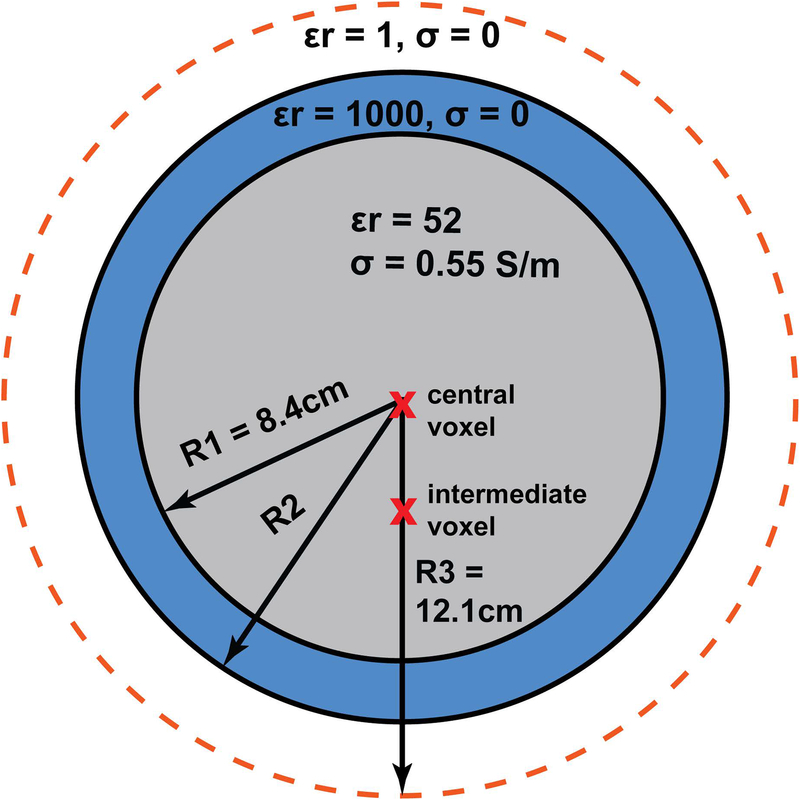
We modeled a uniform sphere with a radius of 8.4 cm and average brain electrical properties (εr = 52, σ = 0.55 S/m) (21) to approximate a human head in an analytical simulation framework based on DGF (12,13,16,22), which was used for all electrodynamic calculations. We defined a basis set of current modes on a spherical surface concentric with the object and at a distance of 3.7 cm from its surface. Each current mode was treated as one detector of a hypothetical coil array and the corresponding EM fields were calculated using the appropriate DGF. Mode expansion orders from l = 0 to l = 60 were used, corresponding to a total of 7442 modes, equally divided among divergence-free and curl-free current contributions, in order to ensure convergence of all DGF calculations (23). The space between the object and the current surface was either partially filled with a continuous layer of HPM or left empty (Fig. 1). The thickness of the HPM layer was varied to correspond to a fraction of the EM wavelength within the HPM, based on the relationship
| [1] |
where f was set to 297.2 MHz, the proton Larmor frequency at 7 T, μ0 is the magnetic permeability of free space and ε = εrε0 is the product of the relative permittivity (εr) and the permittivity of free space (ε0). We used εr = 1000, and varied the thickness of the HPM from 0.8 cm (λ/4) to 3.2 cm (λ). We also included simulations with εr = 100, σ = 0.08 S/m and εr = 250, σ = 0.4 S/m which correspond to properties of titanate slurries previously used for HPM applications at 7 T (14,24,25). HPM thickness was equal to 2.5 cm (λ/4) and 5 cm (λ/2) for εr = 100, and to 1.6 cm (λ/4) and 3.2 cm (λ/2) for εr = 250. For these two cases, the current surface radius was increased from 12.1 cm to 14 cm, to allow the HPM layer to fit between the object and the current surface.
Figure 1:
Simulation setup. Current patterns were evaluated for two voxel locations (red crosses) inside a spherical sample: a central voxel and an intermediate voxel at 3.4 cm from the center. The dielectric sphere shown in gray was surrounded by a continuous layer of high-permittivity material (blue), with a thickness (R2–R1) varied between quarter wavelength (λ/4) and full wavelength (λ) in the HPM at the operating frequency of 297.2 MHz. The radius R3 of the surface where the current patterns were defined (orange dotted line) was kept constant, except for the results shown in Figure 10, for which it was increased to 14 cm to accommodate thicker HPM layers.
Two voxels of interest were considered: one at the center of the sphere, and one at a distance of 3.4 cm from the center (Fig. 1). For each HPM configuration, the current modes were combined with the weights Wicp to obtain the ideal current patterns corresponding to UISNR at the voxel of interest (16):
| [2] |
where S is a vector consisting of the signal sensitivity (B1–) at the voxel of interest for each mode, the superscript H indicates the conjugate transpose, and Ψ is the noise covariance matrix of the modes. The elements of Ψ were calculated as with mode indices i and j. In order to separate the effects of HPMs on signal and noise, we also calculated the weights to obtain signal-only optimal current patterns (WOP) by replacing the matrix Ψ in Eq. [2] with a diagonal matrix with elements Ψii proportional to the current amplitude of each mode i integrated over the current-bearing surface (20). The signal-only optimal current patterns, therefore, represent the most efficient current density to achieve unit B1– at the voxel of interest (or, equivalently, the current density which would maximize the ratio of MR signal to coil noise), whereas the ideal current patterns achieve unit signal sensitivity while also minimizing sample noise. We then defined a third set of combination weights as WDM = EICP − WOP, to obtain “dark mode” current patterns, which achieve a net zero signal sensitivity at the voxel of interest, and which cancel as much sample noise as possible from the signal-only patterns. Adding the signal-only optimal current patterns to the dark mode current patterns yields the ideal current patterns associated with optimal SNR. For additional physical intuition see reference (20).
To further investigate how HPMs affect sample noise, we calculated the net EM fields associated with the three types of current patterns by applying the corresponding combination weights to the modes’ EM fields. We also compared the resulting sample noise values, which were computed as the square root of WΨWH, where W is the vector containing the combination weights for either ideal, signal-only optimal, or dark mode current patterns.
To verify our results for practical coil arrays, we calculated SNR maps (26,27) for finite arrays of 32 and 128 loop coils encircling the spherical object and HPM layer. Coil conductor losses, assuming copper conductors with a conductivity of 58 × 106 S/m and a thickness equal to the skin depth at the operating frequency, were included in the SNR calculations (16,28). Loop coils were defined as weighted combinations of the basis current modes (16) and SNR maps were calculated for a central transverse slice.
RESULTS
As expected from their definition, the mode combinations resulting in ideal and signal-only optimal current patterns achieved unit sensitivity (B1– = 1) at the voxel of interest for all cases, whereas the weights associated with dark mode current patterns resulted in zero signal sensitivity (B1– = 0).
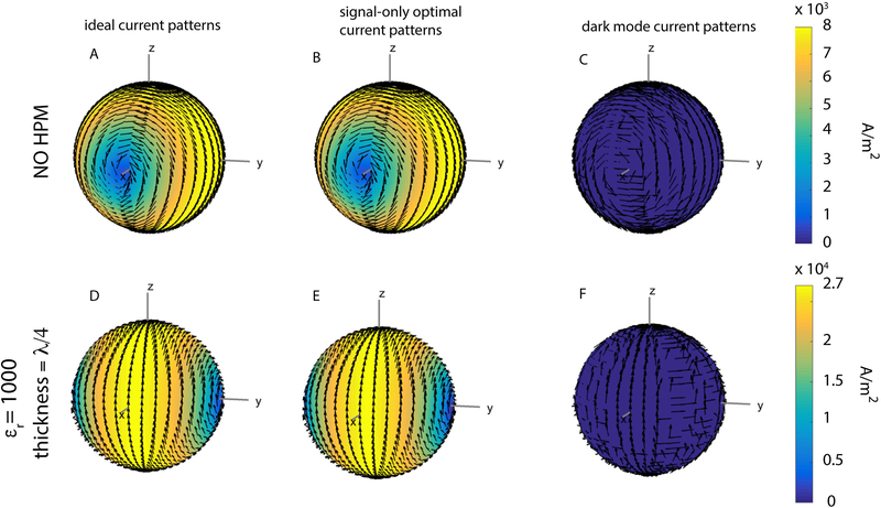
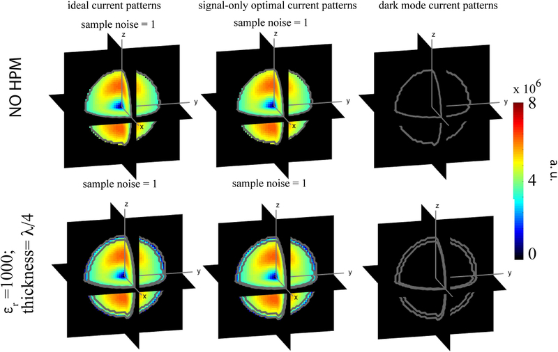
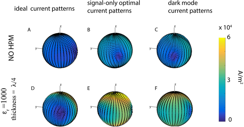
For the central voxel, ideal and signal-only optimal current patterns were identical, with a configuration resembling two distributed current loops precessing around the B0 axis (z−axis) at the Larmor frequency (Fig. 2: A, B, D, E). Note that, in the presence of HPM, the current patterns exhibited a phase shift and required a higher magnitude to achieve unit signal sensitivity (Fig. 2 D–E vs. A–B). However, the corresponding sample noise and signal sensitivity (unity at the voxel of interest) remained the same, indicating that the UISNR was not affected by the presence of HPM (Fig. 3). The dark mode current patterns (Fig. 2C, F) and the corresponding electric field modulus ||E|| (Fig. 3) were vanishingly small, demonstrating that the same current patterns that optimized signal sensitivity also maximized SNR.
Figure 2:
Snapshots at time zero of various current patterns optimized for the central voxel. Arrows indicate surface current direction, and current amplitude is indicated by color, with yellow being high and blue being low. The ideal current patterns and the signal-only optimal current patterns are identical, and the dark mode current patterns are vanishingly small, for this central voxel, both for the case without HPM (A-C) and for the case with an HPM layer with relative permittivity εr =1000 and thickness = λ/4 (D-F). In the presence of HPM (D, E), the current patterns exhibit a rotational phase shift with respect to the patterns in the absence of HPM, and current amplitude is higher in the presence of HPM (note the different colorbar limit).
Figure 3:
The modulus of the electric field ||E|| corresponding to the basis mode combination that results in the current patterns shown in Figure 2 (central voxel). Either with or without a layer of HPM, ||E|| and sample noise are identical for the ideal current patterns and the signal-only optimal current patterns, while the ||E|| corresponding to the dark mode current patterns is vanishingly small. The sample noise, calculated as the sample conductivity times the integral of ||E||2 over the volume of the dielectric sphere, was normalized by the value obtained or the ideal current pattern case without HPM.
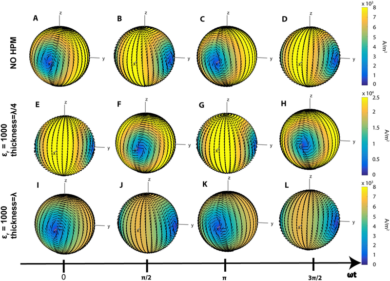
The time evolution of the ideal current patterns for the central voxel are shown in Figure 4, illustrating that the phase shift introduced by the HPM layer depended upon its thickness. For example, a HPM thickness corresponding to a quarter of a wavelength resulted in a rotational phase shift approximately equal to 90 degrees (Fig. 4: E–H vs. A–D). When the thickness corresponded to a full wavelength, the phase shift was 360 degrees, and the ideal current patterns were in phase with those for the case without HPM (Fig. 4: I–L vs. A–D).
Figure 4:
Time evolution of the ideal current patterns associated with UISNR at the central voxel for the case without HPM (A-D), and with a HPM layer of thickness corresponding to λ/4 (E-H) and λ (I-L). The ideal current patterns have the same shape in all cases but exhibit phase advancement proportional to the thickness of the HPM. For example, the time snapshot in E, associated with a 90o phase advancement, corresponds to that in D, whereas the time snapshot in I is phase shifted by 360 degrees with respect to the one in A. The magnitude of the ideal current patterns also depends on the thickness of the HPM layer: stronger (E-H) or weaker (I-L) currents are needed to achieve the UISNR at the center for thickness of the HPM equal to λ/4 or λ, respectively.
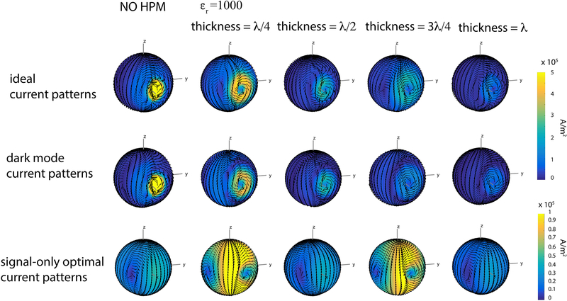
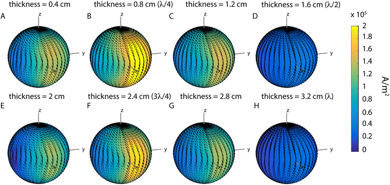
Figure 5 shows temporal snapshots (at t = 0 for all cases) of the ideal, dark mode, and signal-only optimal current patterns associated with the intermediate voxel for different thicknesses of the HPM layer. The magnitude of both ideal and dark mode current patterns was always lower in the presence of HPM and decreased monotonically with the thickness of the HPM layer. The size of the ideal current patterns increased for the cases with thickness corresponding to either a quarter or three quarters of a wavelength. For these cases, the magnitude of the signal-only current patterns also increased considerably. While the signal-only optimal current patterns formed large distributed loops, the dark mode current patterns formed a localized high magnitude loop near the voxel of interest, surrounded by a larger and more distributed current loop circulating in the opposite direction with lower current magnitude (Fig. 5, second row). To assess whether the trends in magnitude and size were time independent, the absolute magnitude of the complex current patterns (included in Supporting Information Figure S1) was also evaluated, which removed features associated with any specific temporal snapshot. The results (Sup. Fig. S1) showed the same trends as observed in Figure 5. Figure 6 confirms that the highest and lowest current magnitudes occurred for thickness of the HPM layer corresponding to odd and even multiples of a quarter wavelengths, respectively, whereas the current magnitude was between these two extreme values for other thicknesses.
Figure 5:
Snapshots (at t = 0) of the current patterns for the intermediate voxel. The amplitude of the signal-only optimal current patterns (row 3) is considerably larger in the cases of HPM with thickness equal to λ/4 and 3λ/4, which also result in the most distributed ideal current patterns (row 1). The amplitude of the dark mode current patterns (row 2) decreases as the thickness of the HPM layer increases.
Figure 6:
Absolute magnitude of signal-only optimal current patterns for the intermediate voxel for increasing thickness of the HPM layer with εr =1000. The highest and lowest amplitudes of the current patterns are obtained when the HPM thickness is an odd or even multiple of λ/4, respectively. The current amplitude for the other HPM layers is intermediate between the highest and lowest cases.
Signal-only optimal and dark mode current patterns were almost equal in magnitude but opposite in vector direction in regions of the spherical surface far from the voxel of interest. As a result, the corresponding SNR-optimal ideal current patterns had very low magnitude in these regions (Fig. 7).
Figure 7:
Temporal snapshots of the current patterns for the intermediate voxel, viewed from the side furthest away from the voxel position (i.e., the view is rotated by 180 degrees azimuthally with respect to Figure 5). Away from the voxel of interest, dark mode and signal-only optimal current patterns are approximately equal in magnitude and opposite in vector direction, resulting in low-amplitude ideal current patterns in these regions.
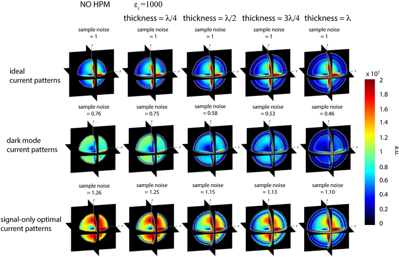
Figure 8 shows the electric field modulus ||E|| corresponding to the current patterns in Figure 5. Although sample noise, which is the integrated net E field over the volume, and the spatial E field distribution associated with the ideal current patterns were the same for all cases, the ideal current patterns varied based on the particular HPM configuration. This indicates that while the presence of a lossless HPM layer does not change the UISNR, since both signal sensitivity and sample noise remain constant, it affects the shape and amplitude of the associated ideal current patterns (Fig. 5 and Sup. Fig. S1). Sample noise for the signal-only optimal cases, on the other hand, decreased monotonically with increasing thickness of the HPM layer, suggesting that the HPM layer can reduce the degree to which E fields permeate the sample, while still achieving unit signal sensitivity at the voxel of interest.
Figure 8:
The modulus of the electric field ||E|| corresponding to the current patterns for the intermediate voxel in Figure 5. For the ideal current patterns, the sample noise is not affected by the HPM layer. As sample noise for signal-only optimal current patterns decreases with an increase in thickness of the HPM layer, the corresponding dark mode current patterns required to achieve the UISNR at the voxel of interest have lower amplitude (Fig. 5). A greater amount of electric field is confined within the HPM layer for signal-only current pattern cases with a lower sample noise. Note that the sample noise was normalized by the value associated with the ideal current patterns.
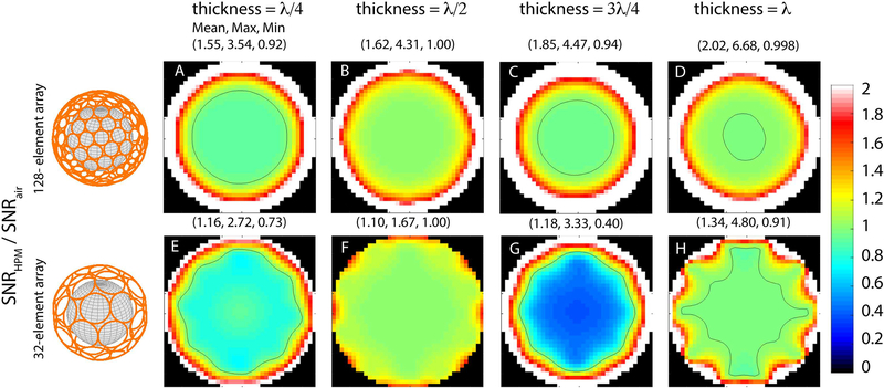
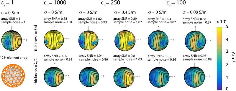
The SNR gain associated with the presence of an HPM layer (εr = 1000) for the case of a 128- or 32-element array surrounding the object are shown in Figure 9. For both arrays, SNR improved at locations near the surface in all cases, but decreased at intermediate locations for HPM thickness corresponding to a quarter and three quarters of a wavelength. The largest SNR improvement at intermediate locations was observed for the case with HPM thickness corresponding to half a wavelength, for which the corresponding signal-only optimal currents had a lower magnitude than the case without HPM (Fig. 10). On the other hand, the magnitude of the signal-only optimal currents was considerably higher when the HPM thickness was equal to a quarter wavelength, and the resulting array SNR was lower near the particular voxel of interest. The same trend was observed with εr = 250, whereas for εr = 100 the current magnitude was approximately the same for HPM thickness = λ/4 and λ/2 (Fig. 10). For εr = 100, the SNR of the 128-element array at the intermediate voxel was approximately the same for both thicknesses, whereas for εr = 1000 and 250 the SNR was higher for HPM thickness equal to λ/2 vs. λ/4. When conductive losses within the HPM layer were included, array SNR decreased, while the sample noise and magnitude of the currents increased. These results suggest that to observe a coil performance gain with thicker HPM layers, the conductivity of the material has to be nearly zero.
Figure 9:
SNR gain relative to the thickness of the HPM layer (εr =1000) for a 128-element (A-D) and 32-element (E-H) array of loops fully encircling the spherical sample. The black contour line indicates regions where the SNR remains constant (i.e., ratio equal to one). For both arrays, the performance in the central region is higher when the thickness of the HPM layer corresponds to λ/2 or λ. Array performance increases for all cases near the surface of the sample. Performance at intermediate locations decreases for HPM with thickness equal to λ/4 or 3λ/4, which correspond to the cases that required larger current magnitude to achieve unit signal sensitivity at the intermediate voxel (see Figure 5 and 6).
Figure 10:
Signal-only optimal current patterns for the intermediate voxel, for different electrical properties and thickness of the HPM layer at 7 T. The thickness was chosen equal to either a quarter (top row) or half (bottom row) the EM wavelength inside the HPM layer, based on its relative permittivity. Note that the radius of the current surface was increased from 12.1 cm (Fig. 1) to 14 cm to account for the larger thickness resulting from smaller εr values. For each case, sample noise and SNR of the 128-element array are reported above the current plot, normalized by the values for the case without HPM. For HPM without conductivity and εr equal to either 1000 or 250, the amplitude of the current was higher for thickness equal to λ/4 than λ/2. For εr = 100, the current amplitude was approximately the same for the two HPM thickness values, and lower compared to the case without HPM (εr = 1, σ = 0 S/m). For HPM with conductivity, array SNR decreased, whereas the sample noise and amplitude of the currents increased. In all cases, the phase of the current patterns advanced in the presence of HPM by an amount corresponding to the thickness of the material, which is approximately 90 and 180 degrees for λ/4 and λ/2, respectively.
DISCUSSION
The aim of this work was to separately investigate signal optimization and sample noise minimization to understand how HPMs can result in SNR improvements for RF coil arrays. The inherent difference between maximizing B1–at a particular voxel and minimizing E field within the entire sample volume allows for separating signal optimization and noise minimization effects to some extent, although in principle the E and B fields are concomitant.
Our results demonstrated that the signal-only optimal and ideal current patterns were equivalent for a central voxel (Fig. 2). The absence of dark mode current patterns (Fig. 2) can be explained by the fact that only a single current mode contributes to the signal sensitivity at the center of a sphere (29), limiting the degrees of freedom to simultaneously minimize sample noise. Phase advancement in the ideal and signal-only current patterns in the presence of HPM (Figs. 2 and 4) indicates that the current pattern optimization has accounted and compensated for the phase delay encountered by the signal propagating through the HPM layer. Phase advancement was also observed for the intermediate voxel, signifying an appreciable signal-propagation delay for voxels that are closer to the surface of the sphere in the presence of HPM (Fig. 5).
The larger magnitude of the signal-only current patterns for a HPM thickness corresponding to λ/4 (Figs. 4–6) and 3λ/4 (Figs. 5 and 6) suggests that, for particular configurations, HPMs can effectively reduce field propagation into the sample, requiring stronger currents to achieve a unit signal sensitivity at the voxel of interest. (Note that for our simulations we used the EM field generated by the current patterns to calculate signal sensitivity and sample noise that would be detected by the same current patterns if they were used as a receive coil via the principle of reciprocity. Therefore, our results indicate that the signal received from a precessing nuclear spin would be weaker if the thickness of the HPM layer is an odd multiple of λ/4.) This shielding effect results in larger ideal current patterns (Fig. 5), which suggests that for these particular HPM configurations larger current loops may be required to improve signal sensitivity and achieve high array SNR (30). From a practical point of view, this suggests that by adding HPMs it could be possible to approach the UISNR with a smaller number of larger coils than would be needed in the absence of HPMs. These observations on the size and amplitude of the current patterns are not specific to the particular temporal snapshot shown in Fig 5, since the same trends were observed after removing any time dependency from the current patterns (see Sup. Fig. S1). The results in Figure 6 confirm that HPM thicknesses equal to odd and even multiples of λ/4 correspond to the highest and lowest magnitude of the signal-only optimal currents, respectively, for the particular relative permittivity considered.
The results for the intermediate voxel show that optimizing for signal reception alone is not sufficient to maximize SNR away from the center. In fact, significant dark mode current patterns were needed to cancel much of the E field created by the signal-only optimal currents over the volume of the sphere, especially in regions far from the voxel of interest (Fig. 7). These dark modes current patterns were stronger near the location of the voxel of interest, in order to restore unit sensitivity for the SNR-optimal configuration (Fig. 5).
Sample noise associated with signal-only optimal currents decreased for increasing HPM thickness (Fig. 8). This could be explained by a shielding effect, which confined E field within the HPM layer, reducing the extent to which the electric field permeated the sample, while still achieving unit signal sensitivity at the voxel of interest. The corresponding monotonic decrease in the amplitude of the dark mode current patterns (Fig. 5 row 2) confirmed that the E field that needed to be canceled to achieve the UISNR was smaller for larger HPM thickness. Note that the UISNR calculation for a voxel converged to the same value in the presence of the lossless HPM as in its absence. The shape of the ideal current patterns surrounding the spherical sample, which reflects the relative weighting of each current mode, changed for different HPM thicknesses to account for any perturbation in the EM field caused by the HPM.
The results in Figure 9 suggest that the magnitude of the signal-only optimal current patterns (Fig. 5) could be used to identify HPM configurations that yield high array SNR performance. For example, HPM with thickness equal to odd multiples of λ/4, which corresponded to high signal-only optimal current amplitude, resulted in the lower array performance at intermediate voxel locations (Fig. 9). Our results also suggest that high amplitude signal-only currents can be used to identify HPM layers that shield the EM field from the imaging sample. As discussed earlier, the sample noise for the signal-only cases decreased monotonically for thicker HPM layers (Fig. 8, row 3), even for layers that shielded the EM field from the sample (odd multiples of λ/4), resulting in an increase in signal-optimal SNR. However, SNR gain in the presence of HPM was poor at intermediate locations, for layers corresponding to an odd multiple of λ/4 (Fig. 9). Note that this effect can be partially compensated by using a larger number of array elements (Fig. 9 top vs. bottom row). The results suggest that a large number of small loops can more closely mimic the high dynamic range and sharp transitions shown by the signal-only optimal current patterns (Fig. 5) even when the HPM considerably shields the EM field. On the other hand, lower signal-only current amplitudes (Fig 5, row 3), which corresponded to HPM with thickness equal to even multiples of λ/4, yielded high performance gains near the voxel of interest (Fig. 9). This result suggests that the HPM configurations that allow displacement currents to propagate into the sample, and reduce the required signal-only current amplitude to achieve unit signal sensitivity, are promising design options for high coil performance. Alternatively, a coil array closer to the sample could also yield a gain in SNR (Supporting Information Figure S2). However, our results showed that the SNR gain provided by HPM could still be greater than the improvement resulting from moving the array elements closer to the sample, especially at the surface (Fig. 9 vs. Sup. Fig. S2). Furthermore, a prior optimization study showed that using an HPM pad in conjunction with a surface coil provided greater degrees of freedom for RF coil design and resulted in higher coil performance than for the case of a surface coil alone (31).
The array SNR gain with HPM (Fig. 9) in the central region of the object was negligible, because encircling arrays (in the absence of HPM) with 32 elements can already achieve 98% of central UISNR in a brain-mimicking uniform sphere at 7 T (28). On the other hand, it is difficult to approach UISNR near the surface, and even 96 closely packed coils can only achieve 10% of the optimum (28). This large margin for improvement could explain why some HPM configurations could increase array SNR by more than four times at the surface (Fig. 9). For cases in which the HPM was more effective in keeping the EM field from propagating into the sample, i.e., for thickness corresponding to odd multiples of λ/4 (Fig. 5), the SNR gain near the surface was higher. This suggests that the larger EM field confined in the HPM layer created stronger displacement currents within the HPM, which induced larger local B1– enhancements near the surface. Note that central SNR could also increase with the addition of an HPM layer in the case of coil array geometries that do not effectively approach the UISNR at the center, such as encircling arrays with a smaller number of elements or coil arrangements that do not completely surround the sample. For example, it was shown that for an 8-channel helmet array, SNR not only improved for locations near the surface but also for locations closer to the center (32).
In this work, a relative permittivity of 1000 was used to incorporate a full range of HPM thicknesses (0 to λ) within the limited space between the spherical sample and the surface where the current distribution was defined. However, HPMs with lower relative permittivity are generally used at 7 T (14,24,25). Therefore, we also investigated signal-only optimal current patterns and coil performance (Fig. 10) using either a relative permittivity of 100, achievable in practice with aqueous suspensions of calcium titanate powder (24), or a relative permittivity of 250, which can be achieved with aqueous suspensions of barium titanate powder (14). To investigate the effect of signal propagation on the shape of the current patterns, the thickness of these HPM pads was chosen to correspond to either λ/4 or λ/2, which resulted in larger thicknesses than those reported in previous work (14). Our results (Fig. 10) suggested that εr = 100 is nearly optimal at 7 T, as shown also in previous work (13,24). However, we demonstrated that HPMs with higher relative permittivities can yield a similar coil performance gain, while being considerably thinner. Including losses in the HPM pads lowered array SNR, suggesting that aqueous suspensions of titanate powders, which are associated with a significant conductivity (14,24,25), should be avoided especially when using thicker HPMs surrounding the sample. Alternatively, HPM pads with very high relative permittivity and almost zero conductivity, which would better match our simulations, could be obtained using ceramics sintered at high temperatures (33,34). However, such manufacturing techniques can be expensive.
In order to design RF coil arrays integrated with HPM, the array elements must be tuned, matched, and decoupled in the presence of the HPM (35–37); therefore, a new simulation must be set up every time the geometry or properties of the HPM are updated when searching for the optimal configuration. Recent work has demonstrated that projecting the E fields created by a precessing spin at a point of interest onto a surface results in a tangential pattern that is proportional to the signal-only optimal current pattern for a voxel occupying that same point (20). This relationship between tangential field patterns and optimal current patterns is a manifestation of the so-called Optimality Principle (20), which is itself a direct consequence of the principle of reciprocity. The tangential E fields in question can be calculated in numerical simulations by modeling a precessing nuclear spin with two magnetic dipoles mutually orthogonal and driven in quadrature (20,38). Since our results suggest that the amplitude of signal-only optimal current patterns could be used to identify favorable HPM configurations, the tangential E fields of a synthetic magnetic spin for a particular imaging body and current surface could provide a faster and simpler alternative to running multiple full EM field simulations to find optimal HPM configurations.
The analytic DGF simulation framework can model only continuous layers encircling the imaging sample (12) (39), which limits the generality of our results. In particular, several studies used discrete localized HPM pads or discs placed between the coil and the sample (8,11,31,40), and only few studies have explored the use of large encircling HPM layers, particularly for head imaging (6,9,41). However, even for discrete HPM pads, coil performance has typically been evaluated in terms of transmit sensitivity when normalized to the energy dissipated in the sample (11), analogous to receive sensitivity normalized by the volume integral of the E-field as employed here. Therefore, we anticipate that our work separating the effects on signal optimization and sample noise in the presence of HPM would provide a better understanding even in cases with discrete HPM pads, although the benefit of HPM for reducing sample noise may be lower in such cases. In addition, as performance trends of completely encircling coils and helmet-like coil arrangements with space provided for the face and neck of the patient are comparable (28,42), we anticipate that our results presented for a spherical sample would benefit studies targeting high performance coil-array designs for head imaging.
Another limitation of our study is that we used a uniform sphere to model the human head. However, since recent work showed that this might be a reasonable approximation for UISNR calculations (43), we anticipate that our observations on signal- and noise-related effects in the presence of HPM would not change considerably in the case of a realistic human head model. Future work will include exploring signal-only optimal and dark mode current patterns for heterogeneous anatomical models and practical coil substrates, using a generalization of the Optimality Principle, which allows SNR-optimizing ideal current patterns to be derived as perturbations of signal-only optimal patterns computed from tangential electric fields (20). The ultimate aim of such work will be to design and build the next generation of high-performance RF coil arrays integrated with HPM.
CONCLUSIONS
We presented a framework to decompose ideal current patterns associated with UISNR into signal-only optimal and noise-minimizing dark mode current patterns, to understand how HPM can affect the EM field distribution in the sample to improve SNR. While the presence of lossless HPM did not change the UISNR, it did change the distribution of B and E fields, and therefore affected the relative balance of signal-only optimal and dark mode current patterns. We showed that signal-only optimal current patterns could be used to identify HPM configurations that lead to SNR gains when using actual coil arrays, while dark mode current patterns could be used to identify HPM geometries that reduce sample noise. This work provides physical insights to understand the effect of HPM on signal propagation and noise minimization, which could be used to guide the design of future RF coils integrated with HPM.
Supplementary Material
Supporting Information1 Figure S1: Absolute magnitude of complex current patterns, which removes features associated with any temporal snapshot, for the intermediate voxel for thickness of the HPM layer corresponding to integer multiples of λ/4. Ideal current patterns have higher amplitude and are distributed over a larger region when the thickness is equal to λ/4 and 3λ/4. For the same two cases, the signal-only optimal currents require a larger magnitude to achieve unit signal sensitivity at the voxel of interest.
Supporting Information1 Figure S2: SNR gain resulting from moving coil arrays closer to the sample in the absence of HPM. The elements of the coil array (either 32 or 128 element array) were positioned at a distance of 1.6 cm from the sample (radius R3 = 10 cm) and the resulting SNR maps were divided by the corresponding SNR maps for the case in which the coil array was positioned at a distance of 3.7 cm (radius R3 = 12.1 cm). These results show that, in the absence of HPM, a gain in SNR can be achieved by positioning the array closer to the sample. However, certain HPM configurations still provide a greater SNR advantage throughout the sample (Fig. 9B, F), especially near the surface (Fig. 9).
ACKNOWLEDGMENT
This work was supported in part by NIH R01 EB002568, NIH R01 EB024536, NIH R01 EB0011551, NIH R01 EB021277 and NSF 1453675, and it was performed under the rubric of the Center for Advanced Imaging Innovation and Research (CAI2R, www.cai2r.net), a NIBIB Biomedical Technology Resource Center (NIH P41 EB017183). The authors would like to thank Giuseppe Carluccio and Jan Paska for insightful discussions and suggestions.
REFERENCES
- 1.Hoult DI. Sensitivity and Power Deposition in a High-Field Imaging Experiment. J Magn Reson Imaging 2000;12(1):46–67. [DOI] [PubMed] [Google Scholar]
- 2.Collins CM, Smith MB. Signal-to-noise ratio and absorbed power as functions of main magnetic field strength, and definition of “90 degrees“ RF pulse for the head in the birdcage coil. Magn Reson Med 2001;45(4):684–691. [DOI] [PubMed] [Google Scholar]
- 3.Keltner JR, Carlson JW, Roos MS, Wong ST, Wong TL, Budinger TF. Electromagnetic fields of surface coil in vivo NMR at high frequencies. Magn Reson Med 1991;22(2):467–480. [DOI] [PubMed] [Google Scholar]
- 4.Vaidya MV, Collins CM, Sodickson DK, Brown R, Wiggins GC, Lattanzi R. Dependence of B1− and B1+ field patterns of surface coils on the electrical properties of the sample and the MR operating frequency. Concepts Magn Reson Part B Magn Reson Eng. 2016; 46(1): 25–40. [DOI] [PMC free article] [PubMed] [Google Scholar]
- 5.Alsop DC, Connick TJ, Mizsei G. A spiral volume coil for improved RF field homogeneity at high static magnetic field strength. Magn Reson Med 1998;40(1):49–54. [DOI] [PubMed] [Google Scholar]
- 6.Yang QX, Mao W, Wang J, Smith MB, Lei H, Zhang X, Ugurbil K, Chen W. Manipulation of image intensity distribution at 7.0 T: passive RF shimming and focusing with dielectric materials. J Magn Reson Imaging 2006;24(1):197–202. [DOI] [PubMed] [Google Scholar]
- 7.Neufeld A, Landsberg N, Boag A. Dielectric inserts for sensitivity and RF magnetic field enhancement in NMR volume coils. J Magn Reson 2009;200(1):49–55. [DOI] [PubMed] [Google Scholar]
- 8.Teeuwisse WM, Collins CM, Wang C, Yang Q, Ma W, Smith N, van Osch M, Webb A. Improvement in high field pulsed arterial spin labeling using dielectric pads: a simulation and experimental study. In: Proceedings of the Joint Annual Meeting of ISMRM-ESMRMB, Stockholm, 2010. (abstract 3863). [Google Scholar]
- 9.Yang QX, Wang J, Wang J, Collins CM, Wang C, Smith MB. Reducing SAR and enhancing cerebral signal-to-noise ratio with high permittivity padding at 3 T. Magn Reson Med 2011;65(2):358–362. [DOI] [PMC free article] [PubMed] [Google Scholar]
- 10.Teeuwisse WM, Brink WM, Webb AG. Quantitative assessment of the effects of high-permittivity pads in 7 Tesla MRI of the brain. Magn Reson Med 2012;67(5):1285–1293. [DOI] [PubMed] [Google Scholar]
- 11.Brink WM, Webb AG. High permittivity pads reduce specific absorption rate, improve B1 homogeneity, and increase contrast-to-noise ratio for functional cardiac MRI at 3 T. Magn Reson Med 2014;71(4):1632–1640. [DOI] [PubMed] [Google Scholar]
- 12.Lattanzi R, Vaidya MV, Carluccio G, Sodickson DK, Collins CM. Signal-to-Noise Ratio gain at 3T using a thin layer of high permittivity material inside enclosing receive arrays. In: Proceedings of the 22nd Annual Meeting of ISMRM, Milan, Italy, 2014. (abstract 4814). [Google Scholar]
- 13.Lattanzi R, Vaidya MV, Carluccio G, Sodickson DK, Collins CM. Effects of high-permittivity materials on absolute RF coil performance as a function of B0 and object size. In: Proceedings of the 22nd Annual Meeting of ISMRM, Milan, Italy, 2014. (abstract 4818). [Google Scholar]
- 14.Teeuwisse WM, Brink WM, Haines KN, Webb AG. Simulations of high permittivity materials for 7 T neuroimaging and evaluation of a new barium titanate-based dielectric. Magn Reson Med 2012;67(4):912–918. [DOI] [PubMed] [Google Scholar]
- 15.Webb AG. Dielectric Materials in Magnetic Resonance. Concepts in Magnetic Resonance Part A 2011;38A(4):148–184. [Google Scholar]
- 16.Lattanzi R, Sodickson DK. Ideal current patterns yielding optimal signal-to-noise ratio and specific absorption rate in magnetic resonance imaging: computational methods and physical insights. Magn Reson Med 2012;68(1):286–304. [DOI] [PMC free article] [PubMed] [Google Scholar]
- 17.Wiggins GC, Zhang B, Lattanzi R, Chen G, Sodickson DK. The Electric Dipole Array: An Attempt to Match the Ideal Current Patterns for Central SNR at 7 Tesla. In: Proceedings of the 20th Annual Meeting of ISMRM, Melbourne, Australia, 2012. (abstract 0541). [Google Scholar]
- 18.Wiggins GC, Zhang B, Cloos M, Lattanzi R, Chen G, Lakshmanan K, Haemer G, Sodickson DK. Mixing loops and electric dipole antennas for increased sensitivity at 7 Tesla. In: Proceedings of the 21st Annual Meeting of ISMRM, Salt Lake City, Utah, 2013. (abstract 2737). [Google Scholar]
- 19.Chen G, Cloos M, Lattanzi R, Sodickson DK, Wiggins GC. Bent Electric Dipoles: A Novel Coil Design Inspired by the Ideal Current Pattern for Central SNR at 7 Tesla. In: Proceedings of the 22nd Annual Meeting of ISMRM, Milan, Italy, 2014. (abstract 0402). [Google Scholar]
- 20.Sodickson DK, Lattanzi R, Vaidya M, Chen G, Novikov DS, Collins CM, and Wiggins GC. The Optimality Principle for MR signal excitation and reception: New physical insights into ideal radiofrequency coil design. arXiv:1808.02087 [physics.ins-det].
- 21.Gabriel C, Gabriel S. Compilation of dielectric properties of body tissues at RF and microwave frequencies. www.brooks.af.mil/AFRL/HED/hedr/reports/dielectric. AL/OE-TR-1996-0037 1996.
- 22.Schnell W, Renz W, Vester M, Ermert H. Ultimate signal-to-noise-ratio of surface and body antennas for magnetic resonance imaging. IEEE Trans. Antennas Propag 2000;48(3):418–428. [Google Scholar]
- 23.Lattanzi R, Sodickson DK, Grant AK, Zhu Y. Electrodynamic constraints on homogeneity and radiofrequency power deposition in multiple coil excitations. Magn Reson Med 2009;61(2):315–334. [DOI] [PMC free article] [PubMed] [Google Scholar]
- 24.Haines K, Smith NB, Webb AG. New high dielectric constant materials for tailoring the B1+ distribution at high magnetic fields. J. Magn. Reson 2010;203(2):323–327. [DOI] [PubMed] [Google Scholar]
- 25.Luo W, Lanagan MT, Sica CT, Ryu Y, Oh S, Ketterman M, Yang QX, Collins CM. Permittivity and performance of dielectric pads with sintered ceramic beads in MRI: early experiments and simulations at 3 T. Magn Reson Med 2013;70(1):269–275. [DOI] [PMC free article] [PubMed] [Google Scholar]
- 26.Roemer PB, Edelstein WA, Hayes CE, Souza SP, Mueller OM. The NMR phased array. Magn Reson Med 1990;16(2):192–225. [DOI] [PubMed] [Google Scholar]
- 27.Kellman P, McVeigh ER. Image reconstruction in SNR units: A general method for SNR measurement. Magn Reson Med 2005;54(6):1439–1447. [DOI] [PMC free article] [PubMed] [Google Scholar]
- 28.Vaidya MV, Sodickson DK, Lattanzi R. Approaching Ultimate Intrinsic SNR in a Uniform Spherical Sample with Finite Arrays of Loop Coils. Concepts in magnetic resonance Part B, Magnetic resonance engineering 2014;44(3):53–65. [DOI] [PMC free article] [PubMed] [Google Scholar]
- 29.Lee H-H, Sodickson DK, Lattanzi R. An analytic expression for the ultimate intrinsic SNR in a uniform sphere. Magn Reson Med 2018;00:1–11. [DOI] [PMC free article] [PubMed] [Google Scholar]
- 30.Vaidya MV, Haemer G, Carluccio G, Novikov DS, Sodickson DK, Collins CM, Wiggins GC, Lattanzi R. Ideal current patterns correspond to larger surface coils with use of high permittivity materials In: Proceedings of the 23rd Annual Meeting of ISMRM, Toronto, 2015. (abstract 3109). [Google Scholar]
- 31.Luo W, Qing Y, Collins CM. Improved surface coil performance at any depth in a lossy sphere with a dielectric disc. In: Proceedings of the 22nd Annual Meeting of ISMRM, Milan, 2014. (abstract 4812). [Google Scholar]
- 32.Haemer GG, Vaidya MV, Collins CM, Sodickson DK, Wiggins GC. Evaluation of a high permittivity helmet for use as a coil former for a 8ch transmit/recieve array with dodecahedral symmetry. In: Proceedings of the 25th Annual Meeting of ISMRM, Hawaii 2017. (abstract 4283). [Google Scholar]
- 33.Koolstra K, Börnert P, Brink W, Webb A. Improved image quality and reduced power deposition in the spine at 3 T using extremely high permittivity materials. Magn Reson Med 2018;79(2):1192–1199. [DOI] [PMC free article] [PubMed] [Google Scholar]
- 34.Rupprecht S, Sica CT, Chen W, Lanagan MT, Yang QX. Improvements of transmit efficiency and receive sensitivity with ultrahigh dielectric constant (uHDC) ceramics at 1.5 T and 3 T. Magn Reson Med 2018;79(5):2842–2851. [DOI] [PMC free article] [PubMed] [Google Scholar]
- 35.Zhang B, Fayad ZA, Xu J, Stoeckel B, Balchandani P. Evaluating the SNR performance of using dielectric pads with multiple channel RF coils at 7T. In: Proceedings of the 16th Annual Meeting of ISMRM, Toronto, 2015. (abstract 1782). [Google Scholar]
- 36.Haemer GG, Collins CM, Sodickson DK, Wiggins GC. Discovering and working around effects of unwanted resonant modes in high permittivity materials placed near RF coils. In: Proceedings of the 23rd Annual Meeting of ISMRM, Toronto, 2015. (abstract 0859). [Google Scholar]
- 37.Haemer GG, Vaidya MV, Collins CM, Wiggins GC. Changes in neighbor and next-nearest neighbor coupling of transmit/recieve arrays in the presence of close-fitting high permittivity materials. In: Proceedings of the 23rd Annual Meeting of ISMRM, Toronto, 2015. (abstract 3104). [Google Scholar]
- 38.Vaidya MV, Collins CM, Sodickson DK, Carluccio G, Lattanzi R. Disentangling Signal propagation and Noise-related Effects in the Presence of High Permittivity Materials via Ideal Current Patterns. In: Proceedings of the 24th Annual Meeting of ISMRM, Singapore, 2016. (abstract 0391). [Google Scholar]
- 39.Pfrommer A, Henning A. On the Contribution of Curl-Free Current Patterns to the Ultimate Intrinsic Signal-to-Noise Ratio at Ultra-High Field Strength. NMR in biomedicine 2017;30(5):e3691–n/a. [DOI] [PubMed] [Google Scholar]
- 40.Snaar JEM, Teeuwisse WM, Versluis MJ, van Buchem MA, Kan HE, Smith NB, Webb AG. Improvements in high-field localized MRS of the medial temporal lobe in humans using new deformable high-dielectric materials. NMR in Biomed 2011;24(7):873–879. [DOI] [PubMed] [Google Scholar]
- 41.Collins CM, Carluccio G, Vaidya MV, Haemer G, Luo W, Lattanzi R, Wiggins GC, Sodickson DK, Yang QX. High-permittivity Materials can Improve Global Performance and Safety of Close-Fitting Arrays. In: Proceedings of the 22nd Annual Meeting of ISMRM, Milan, Italy 2014. (abstract 0404). [Google Scholar]
- 42.Lattanzi R, Grant AK, Polimeni JR, Ohliger MA, Wiggins GC, Wald LL, Sodickson DK. Performance evaluation of a 32-element head array with respect to the ultimate intrinsic SNR. NMR in Biomed 2009;23(2):142–151. [DOI] [PMC free article] [PubMed] [Google Scholar]
- 43.Guérin B, Villena JF, Polimeridis AG, Adalsteinsson E, Daniel L, White JK, Wald LL. The ultimate signal-to-noise ratio in realistic body models. Magn Reson Med 2017;78(5):1969–1980. [DOI] [PMC free article] [PubMed] [Google Scholar]
Associated Data
This section collects any data citations, data availability statements, or supplementary materials included in this article.
Supplementary Materials
Supporting Information1 Figure S1: Absolute magnitude of complex current patterns, which removes features associated with any temporal snapshot, for the intermediate voxel for thickness of the HPM layer corresponding to integer multiples of λ/4. Ideal current patterns have higher amplitude and are distributed over a larger region when the thickness is equal to λ/4 and 3λ/4. For the same two cases, the signal-only optimal currents require a larger magnitude to achieve unit signal sensitivity at the voxel of interest.
Supporting Information1 Figure S2: SNR gain resulting from moving coil arrays closer to the sample in the absence of HPM. The elements of the coil array (either 32 or 128 element array) were positioned at a distance of 1.6 cm from the sample (radius R3 = 10 cm) and the resulting SNR maps were divided by the corresponding SNR maps for the case in which the coil array was positioned at a distance of 3.7 cm (radius R3 = 12.1 cm). These results show that, in the absence of HPM, a gain in SNR can be achieved by positioning the array closer to the sample. However, certain HPM configurations still provide a greater SNR advantage throughout the sample (Fig. 9B, F), especially near the surface (Fig. 9).


