

Abstract
Percutaneous techniques and robot-assisted surgical systems have enabled minimally invasive procedures that offer reduced scarring, recovery time, and complications compared to traditional open surgeries. Despite these improvements, access to diseased sites using the standard, straight needle-based percutaneous techniques is still limited for certain procedures due to intervening tissues. These limitations can be further exacerbated in specific patient groups, particularly pediatric patients, whose anatomy does not fit the traditional tools and systems. We therefore propose a patient-specific paradigm to design and fabricate dexterous, robotic tools based on the patient’s preoperative images. In this paper, we present the main steps of our proposed paradigm – image-based path planning, robot design, and fabrication – along with an example case that focuses on a class of dexterous, snake-like tools called concentric tube robots. We demonstrate planning a safe path using a patient’s preoperative ultrasound images. We then determine the concentric tube robot parameters needed to achieve this path, and finally, we use 3-D printing to fabricate the patient-specific robot.
I. Introduction
Minimally invasive surgical procedures are performed whenever possible due to the reduction in complications and co-morbidity. However, when the surgical target is at a difficult anatomical site, minimally invasive procedures with straight instruments may not be safe. The risks of serious complications may be even higher in pediatric patients, whose anatomy is more compact, and in other specialized patient groups whose anatomy may prove current generalized systems inadequate. To address these limitations, we propose a patient-specific design paradigm. The primary contribution of this work is to demonstrate this entire personalized design process including preoperative 3-D ultrasound imaging, segmentation of surrounding organs, safe path planning, design of a flexible robot, and finally robot fabrication (Figure 1).
Fig. 1.
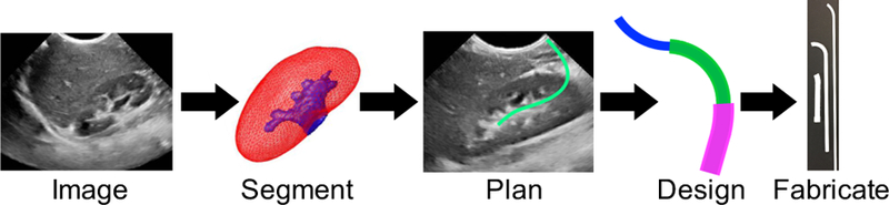
Patient-specific design workflow includes imaging, segmentation, path planning, concentric tube robot design, and fabrication.
A. Medical Application
To ground this work in a particular clinical application, we focus here on accessing kidney stones in pediatric patients through a percutaneous subcostal approach. In a large international multi-institution study of 5,803 patients undergoing percutaneous nephrolithotomy (minimally-invasive procedure to remove stones by puncturing the skin), a complication rate of 21.5% was reported [1]. In a review by Stephan et al., the complication rate was up to 83% [2]. With better planning and dexterity, the number of such injuries and complications could be reduced. Our goal is to avoid damaging nearby tissue by using a subcostal approach that enters below the 12th rib and snakes through the renal pelvis towards the target. Here we focus on the case of an 8-year-old female patient with a 3mm renal calculus located in the interpolar region of the right kidney. Although focused here on pediatric stone removal, the aim is to demonstrate the development of a paradigm that can be applied to other procedures and patient groups in the future.
B. Concentric Tube Robots
Concentric tube robots are snake-like, dexterous robots, consisting of hollow, precurved tubes that nest concentrically, one inside the next [3], [4]. Each tube can be individually rotated and inserted with respect to the others, and the interaction between overlapping tubes of different curvatures enables the robot’s overall shape to change. There are several parameters, including diameters, curvatures, and lengths, that can be adjusted to change the dexterity and accessible workspace, making concentric tube robots a natural choice for personalization. Concentric tube robots are also small and dexterous, since their bending does not rely on external forces, but rather, is inherent in the elastic interaction of the tubes. There are numerous possible sequences of insertions and rotations to deploy a concentric tube robot to a given configuration. In this work, a plan is created for a “follow-the-leader” deployment sequence [5], where the backbone exactly follows the tip. The surgeon can teleoperate the robot with haptic feedback that constrains movement to the desired path, or the system can allow the surgeon to implement other deployment sequences.
II. Image Segmentation and Path Planning
A. Imaging
Abdominal ultrasound is a safe and simple imaging exam that allows diagnosing and monitoring pediatric conditions. For path planning, we acquired three-dimensional (3-D) B-mode ultrasound data to facilitate the visualization and quantification of the kidney and its surrounding region, including a partial view of the liver (for the right kidney). Images were acquired with a Philips iU22 system (Philips Healthcare) with an X6–1 xMATRIX array transducer. The volume size was 496 × 410 × 219 voxels, with a voxel resolution of 0:27 × 0:21 × 0:38 mm.
B. Segmentation
Based on the preoperative 3-D ultrasound scans of the patient, we identified and delineated the renal structures, including the renal parenchyma (SK) and collecting system (SCS ), and the surrounding organs at risk using semi-automatic segmentation. This facilitated the visualization and study of the patient-specific anatomy, and the design of a safe path for the intervention.
For the segmentation of the kidney and collecting system, we used the framework recently presented in [6]. The kidney was first segmented using an active shape model [7] variant, tailored to deal with the high intensity variability and inhomogeneity of ultrasound images. The anatomical coherence of the model is guaranteed via the statistical shape model of the kidney built from 39 pediatric cases. To compensate for the image dependency on the propagation direction of the ultrasound wavefront, the model incorporates an orientation-based landmark weighting model that gives high confidence to the edges normal to the wavefront, and low confidence to features tangential to the sound wave. The model is completed with a new ultrasound appearance descriptor based on multi-scale omnidirectional Gabor filters. represents this initial segmentation of the kidney.
Segmentation of the renal calyces and pelvis are critical to design a minimally invasive access path, since factors including the angle of the access path to the renal calix directly affects how invasive the procedure will be. In particular, we used the active contour-based formulation introduced in [6], which includes the renal fat as a patient-specific anatomical constraint to control the contour evolution process, mimicking the propagation of fluid inside the kidney previously segmented. represents the resulting collecting system segmentation.
Once the renal structures were segmented, a first estimation of the surrounding organs at risk were obtained using a simplified version of the multi-organ statistical shape model described in [8]. For this case study involving the right kidney, the right lung (SRL) and liver (SL) were included in the model. Given the multi-organ statistical shape model, and using as a predictor, and were estimated via a weighted point distribution model [8], where the weights corresponding to SRL and SL were set to zero, while the weights of SK were set to 1. Figure 2(a) shows a 2D view of the resulting and the estimated .
Fig. 2.
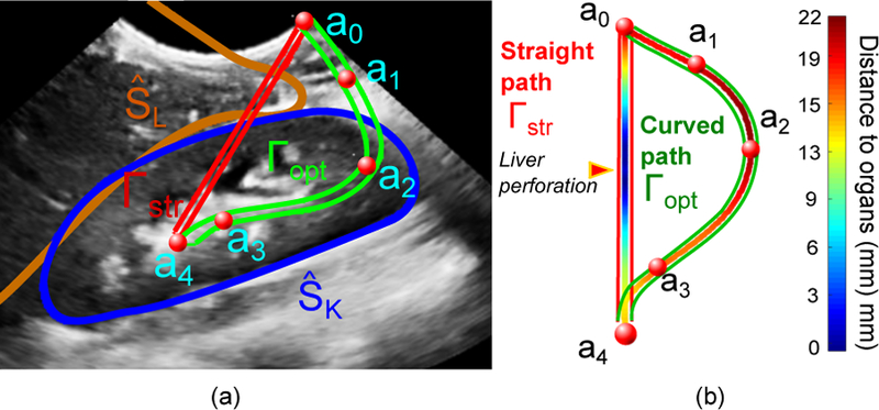
(a) View of the 3-D ultrasound of the patient, showing the control points selected by the surgeon for lateral access (a0 to a4), the closest organ of risk (), and the straight (Γstr) and curved path (Γopt) to access the stone (a4). (b) Colormap representing the distance to critical surrounding organs. Note that the straight path would perforate the liver.
C. Path Planning
The estimated patient-specific anatomical map, (, , , ), along with the 3-D ultrasound volume (for manual correction if necessary) are presented to the specialist (i.e., surgeon or interventional radiologist). The specialist then manually selects the critical points of the curved path by mouse clicks, defining the insertion point on the skin surface (a0), the target point (aN ), as well as any additional control points if necessary (e.g. to control the angle of the instrument to access the calix). Let (aj, j = 0, … , N ) represent the set of selected points. In this case, a total of 5 points were defined, as shown in Figure 2(a). The optimal path, Γopt, is defined as
| (1) |
where is a curved path with C1 continuity connecting the access (a0) and the target (aN) points, and and represent the shortest distance of this path to the segmented organs, , and the control points, aj, respectively. Equation 1 can be solved as a constrained spline problem [9] using the distance map defined by the set of segmented organs. Figure 2(b) shows the distance map of the resulting path to the surrounding organs.
III. Concentric Tube Robot Design and Fabrication
The next step in the patient-specific design process is to design and fabricate a set of concentric tubes that can most closely achieve the desired curved path.
A. Tube Design
1). Curve Fitting:
There are several parameters to select for a given concentric tube robot design. First, the number of tubes (n) must be selected based on the curved path. Here we have chosen n = 3. The next step is to fit regions of constant curvature to the given path. A circle with center () and radius (r) is fit to each segment using two points and a tangent vector as in [10]. We fit one straight region, from to , and three regions of constant curvature, constrained to be tangent to the previous segment (Figure 3(a)).
Fig. 3.
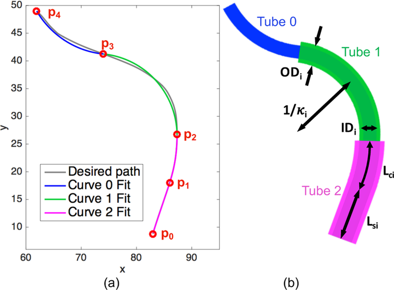
(a) Optimal path (gray) based on image segmentation. Starting and ending points (p0 to p4) of the piece-wise segments are shown in red, along with the curve fits for each segment. (b) Concentric tube robot configuration based on the tube parameters backed out from the curve fits.
In contrast to past work [10], our optimal path does not have defined via points () through which the curves should pass. Instead, we iterate through possible combinations of starting and ending points for the segments. To narrow down the range of combinations, we set as the robot base, as the end of the straight region as fit by eye, and as the robot tip. We then iterated through various and positions, calculating the fits of the resulting segments. The mean square error of the fits for each segment were calculated and weighted by the number of points in the segment. The curvature fits for curves 0, 1, and 2 were 0.0632, 0.0676, and 0.0373 mm−1, respectively (Figure 3(a)).
2). Parameter Selection:
This piece-wise constant curvature path can then be used to determine the curvatures and lengths of each of the concentric tubes. To start, we assume that the final curved section, between points and , represents a section of the robot that consists solely of the innermost tube. Therefore the curvature of the innermost tube (κ0) is equal to the inverse of the radius of curvature fit to this segment. Working back towards the base of the concentric tube robot, each curved segment is assumed to consist of i+1 overlapping tubes, where i is the tube number, starting with i = 0 for the innermost tube. The curvature of such segments lies somewhere in between that of the original precurvatures, and this new equlibrium curvature (keq) can be described for the planar case as [3], [11],
| (2) |
where Ii and Ei are the cross-sectional moment of inertia of tube i and Young’s modulus of tube i, respectively, and m is the number of overlapping tubes. Equation 2 is used to solve for κi of the remaining curved segments. Finally, the curved length of each tube (Lci) is set equal to the length of the corresponding segment of the piece-wise curved path.
The final tube parameters were selected based on the particular patient and procedure. The inner diameter of the smallest tube (ID0) has a lower bound based on the diameter of the flexible tool that must be passed through the concentric tube robot, and the outer diameter of the outermost tube (OD2) has an upper bound based on the size of the patient. The remaining diameters are determined based on the wall thickness required by the fabrication method, as well as the gap between tubes needed for smooth relative motion. The last parameter, the straight length of each tube (Lsi), is determined based on the dimensions of the robot driving the concentric tubes. The final designed parameters are shown in Table I.
TABLE I.
Tube Parameters
| Tube # | OD [mm] | ID [mm] | Lc [mm] | Ls [mm] | κ [mm−1] |
|---|---|---|---|---|---|
| 0 | 2.4 | 1.0 | 14.9 | 200.1 | 0.0632 |
| 1 | 3.8 | 3.0 | 21.6 | 98.6 | 0.0847 |
| 2 | 5.4 | 4.4 | 8.8 | 39.7 | 0.0499 |
B. Tube Fabrication
1). Material and Method:
The designed tube parameters are then used to generate a CAD model, which is subsequently 3-D printed. In contrast to traditional methods patient-specific design methodology [12], [13]. A MakerBot Replicator 2X was used to print polycaprolactone (PCL) (from MakerBot Industries). PCL is a biodegradable polyester, often used for sutures [14]. Once printed, we can insert a flexible inner wire with a sharp tip through the robot to help cut through tissue, and the the entire concentric tube robot can be attached to the driving robot, as shown in Figure 4, in order to assess the final configuration achieved. The robot we have developed to drive the concentric tubes is compact, modular, and can independently control both insertion and rotation of each of the three tubes [15].
Fig. 4.
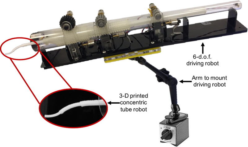
3-D printed concentric tube robot attached to the 6-d.o.f. driving robot that controls both insertion and rotation of each tube individually.
2). Results:
The individual tubes are shown in Figure 5(a). Due to printer resolution and tolerances, there were slight variations between the designed and measured dimensions (Table II). Calipers were used to measure the diameters of the tubes at several points, and minimum and maximum percent errors are given based on these. Curvature measurements were made by comparing the tubes against lines of known constant curvature.
Fig. 5.
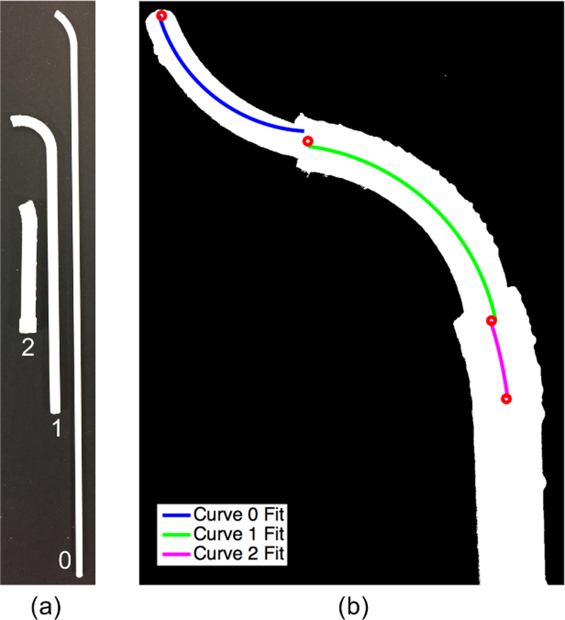
(a) Set of tubes 3-D printed with polycaprolactone (PCL). (b) Overhead view of 3-D printed concentric tube robot in desired configuration with curve fits overlaid on each of the curved segments.
TABLE II.
Tube Parameter Comparison: Showing mean percent error (and minimum and maximum percent error where relevant) between the designed and measured tube parameters.
| mean % error (min % error to max % error) | |||
|---|---|---|---|
| Tube # | OD | ID | κ |
| 0 | 0.4% (−2.9 to 3.8) | 2.0% (−4.0 to 8.0) | 0.4% |
| 1 | −2.0% (−4.2 to 0.3) | −0.8% (−5.0 to 3.3) | −1.6% |
| 2 | 0.4% (−0.2 to 0.9) | −0.6% (−2.3 to 1.1) | −1.0% |
To assess the overall shape of the concentric tube robot, the tubes were arranged concentrically, with the desired relative insertion and rotation. Once arranged in the desired configuration, that would be reached via follow-the-leader deployment, an overhead image was taken in order to analyze the curvatures. As shown in Figure 5(b), the image was converted into a binary image, where the concentric tube robot is shown in white. A centerline through the tubes was then found and segmented by eye into three regions. Constant curvature segments were then individually fit to the centerline in each region, and the resulting fits are shown in Figure 5(b). The radii of curvatures were converted from pixels to millimeters based on a reference ruler (not shown in the image here). The curvatures were found to be 0.078, 0.0571, and 0.0296 mm−1 for curves 0, 1, and 2, respectively. These correspond to deltas of −0.0148, 0.0105, and 0.0078 mm−1 from the desired curvatures. Slight deviations from the exact path are acceptable as long as the concentric tube robot remains within the safe workspace and does not puncture critical organs. We leave further evaluation to future work.
IV. Conclusion
This paper proposes the development of a patient-specific design paradigm and demonstrates the process for planning, designing, and fabricating tools to access a pediatric kidney stone. Results demonstrate the feasibility in 3-D printing a set of concentric tubes based on a desired path planned using a patient’s preoperative ultrasound images. Future work includes a complete demonstration of using these patient-specific tools in a phantom patient model. In addition, we plan to integrate information from the surgeon’s planned path into the control scheme for driving the concentric tubes during a procedure. Finally, this work could be extended to other patient groups and procedures.
Acknowledgment
The authors would like to thank Joseph Greer for help with curve fitting and James Jago from Philips Healthcare for help with imaging equipment.
This work was supported in part by the National Institutes of Health through R01 EB018849, a National Science Foundation Graduate Research Fellowship and a philanthropic gift from the Government of Abu Dhabi to Children’s National Health System.
References
- [1].Taylor E, Miller J, Chi T, and Stoller ML, “Complications associated with percutaneous nephrolithotomy,” Translational Andrology and Urology, vol. 1, no. 4, 2012. [DOI] [PMC free article] [PubMed] [Google Scholar]
- [2].Michel MS, Trojan L, and Rassweiler JJ, “Complications in percutaneous nephrolithotomy,” European Urology, vol. 51, no. 4, pp. 899–906, 2007. [DOI] [PubMed] [Google Scholar]
- [3].Webster RJ III, Okamura AM, and Cowan NJ, “Toward active cannulas: Miniature snake-like surgical robots,” in IEEE/RSJ Int. Conf. Intelligent Robots and Systems, 2006, pp. 2857–2863.
- [4].Sears P and Dupont PE, “A steerable needle technology using curved concentric tubes,” in IEEE/RSJ Int. Conf. Intelligent Robots and Systems, 2006, pp. 2850–2856.
- [5].Gilbert H and Webster III R, “Can concentric tube robots follow the leader?” in Proc. IEEE Int. Conf. Robotics and Automation, 2013, pp. 4881–4887. [DOI] [PMC free article] [PubMed]
- [6].Cerrolaza JJ, Safdar N, Biggs E, Jago J, Peters CA, and Linguraru MG, “Renal segmentation from 3-D ultrasound via fuzzy appearance models and patient-specific alpha shapes,” IEEE Trans. Med. Imag, vol. 35, no. 11, pp. 2393–2402, 2016. [DOI] [PubMed] [Google Scholar]
- [7].Cootes TF, Taylor CJ, Cooper D, and Graham J, “Active shape models - their training and application,” Comp. Vis. Image Underst, vol. 61, no. 1, pp. 38–59, 1995. [Google Scholar]
- [8].Cerrolaza J, Summers R, and Linguraru M, “Soft multi-organ shape model via generalized pca: A general framework,” in MICCAI, 2016, pp. 219–228.28251192
- [9].Hofer M, “Constrained optimization with energy-minimizing curves and curve networks: A survey,” in Proceedings of the 23rd Spring Conference on Computer Graphics, ser. SCCG ‘07. New York, NY, USA: ACM, 2007, pp. 27–35. [Online]. Available: http://doi.acm.org/10.1145/2614348.2614353 [Google Scholar]
- [10].Morimoto TK, Greer JD, Hsieh MH, and Okamura AM, “Surgeon design interface for patient-specific concentric tube robots,” in Int. Conf. on Biomedical Robotics and Biomechatronics, 2016, pp. 41–48. [DOI] [PMC free article] [PubMed]
- [11].Webster R, Romano J, and Cowan N, “Mechanics of precurved-tube continuum robots,” IEEE Trans. Rob, vol. 25, no. 1, pp. 67–78, 2009. [Google Scholar]
- [12].Morimoto TK and Okamura AM, “Design of 3-D printed concentric tube robots,” IEEE Trans. Robotics, vol. 32, no. 6, pp. 1419–1430, 2016. [DOI] [PMC free article] [PubMed] [Google Scholar]
- [13].Amanov E, Nguyen T-D, and Burgner-Kahrs J, “Additive manufacturing of patient-specific tubular continuum manipulators,” Proc. SPIE, vol. 9415, pp. 94 151–94 159, 2015. [Google Scholar]
- [14].Woodruff MA and Hutmacher DW, “The return of a forgotten polymer: Polycaprolactone in the 21st century,” Progress in Polymer Science, vol. 35, no. 10, pp. 1217–1256, 2010. [Google Scholar]
- [15].Morimoto TK, Hawkes EW, and Okamura AM, “Design of a compact actuation and control system for flexible medical robots,” IEEE Robotics and Automation Letters, vol. 2, no. 3, pp. 1579–1585, 2017. [DOI] [PMC free article] [PubMed] [Google Scholar]