

Abstract
This work presents an approach for synchronization and alignment of Digital Imaging and Communications in Medicine (DICOM) series from different studies that allows, e.g., easier reading of follow-up examinations. The proposed concept developed within the DICOM’s patient-based reference coordinate system allows to synchronize all image data of two different studies/examinations based on a single registration. The most suitable DICOM series for registration could be set as default per protocol. Necessary basics regarding the DICOM standard and the used mathematical transformations are presented in an educative way to allow straightforward implementation in Picture Archiving And Communications Systems (PACS) and other DICOM tools. The proposed method for alignment of DICOM images is potentially also useful for various scientific tasks and machine-learning applications.
Keywords: DICOM, Medical image registration, Image alignment, Image coordinate system, Reference coordinate system, Multiparametric analyses
Background
Synchronization of DICOM (Digital Imaging and Communications in Medicine) image data is a common feature of Picture Archiving and Communications System (PACS) viewers. If this function is activated by the user, the simultaneous display of multiple image datasets of a particular examination is instantly synchronized. In our institution, this synchronization function is frequently used for reading of multiparametric magnetic resonance imaging (MRI) datasets. For example, by clicking on a suspicious lesion on a T2-weighted dataset, the currently displayed slice position of all other sequences (e.g., a T1-weighted dataset) is changed accordingly. Additionally, the selected area is marked by a crosshair in all image datasets. This point-to-point live synchronization works independent of the image orientation (e.g., transversal, coronar, sagittal). However, the synchronization of DICOM images without prior registration is limited to datasets that were acquired in a single study. To allow synchronized viewing of follow-up examinations, e.g., for assessment of the progress of a lesion, some form of image registration is required. Some systems already offer such registration functionality (typically as a black-box application) but it is not standard in DICOM viewers for clinical research [1]. Hence, the aim of this project was to present a simple and easy-to-implement approach within the DICOM concept, which allows synchronization and alignment of image data that were recorded in different examinations. In principle, the approach is also applicable to DICOM image data acquired at different modalities.
Methods
This section provides all necessary basics with respect to the DICOM standard and the used mathematical transformations. Transformation matrices are a fundamental prerequisite for live synchronization, which is basically a coordinate transformation between two image coordinate systems (ICSs). Furthermore, it is explained how to create a corresponding transformation matrix based on DICOM metadata, and how it can be applied for live synchronization. The illustrative derivation also points out why this procedure is not adequate for synchronization of image data from different examinations. The proposed solution to this problem is then presented in the result section. All examples were implemented in MATLAB (The MathWorks, Inc., Natick, MA) and C.
Basics of Transformation Matrices
Figure 1 shows two rectangular, right-handed coordinate systems. Curly braces indicate a coordinate system. Suppose we have a certain point A. The coordinates of point A are described in a coordinate system called {1}. Now we want to calculate the coordinates of point A with respect to a different coordinate system {2}. To achieve this, we need the transformation matrix between the two coordinate systems which we denote . The transformation matrix contains information about the position and rotation of the two coordinate systems relative to each other. It is composed of a rotation matrix and the position vector of the coordinate origin . The rotation matrix can be calculated by scalar products of the axes of the mutually rotated coordinate systems [2]. Of note, the algebraic inverse matrix of a transformation matrix also represents the inverse transformation. This means that the transformation matrix that describes the transformation of coordinate system {1} to {2} can be calculated by computing the inverse of the transformation matrix that describes the transition from coordinate system {2} to {1}. Equation 1 shows the structure of a transformation matrix:
| 1 |
where is the origin of coordinate system {2} described in coordinate system {1} and is the rotation matrix, which describes the rotation of {2} to {1}. are the unit vectors of the two coordinate systems that must be described in the same system. To transform the position vector of point A described in the coordinate system {1} (denoted by ) into a position vector that describes point A in coordinate system {2} (), the position vector is extended by a one in the fourth dimension. This type of coordinates are called homogeneous coordinates. Now the position vector can be multiplied by the transformation matrix in :
| 2 |
Note that in the notation used here, there is a mnemonic to the correct sequence of non-commutative matrix multiplication: The system that is to be eliminated from the notation by matrix multiplication must be diagonally opposed from top left to bottom right (highlighted in Eq. 2).
Fig. 1.
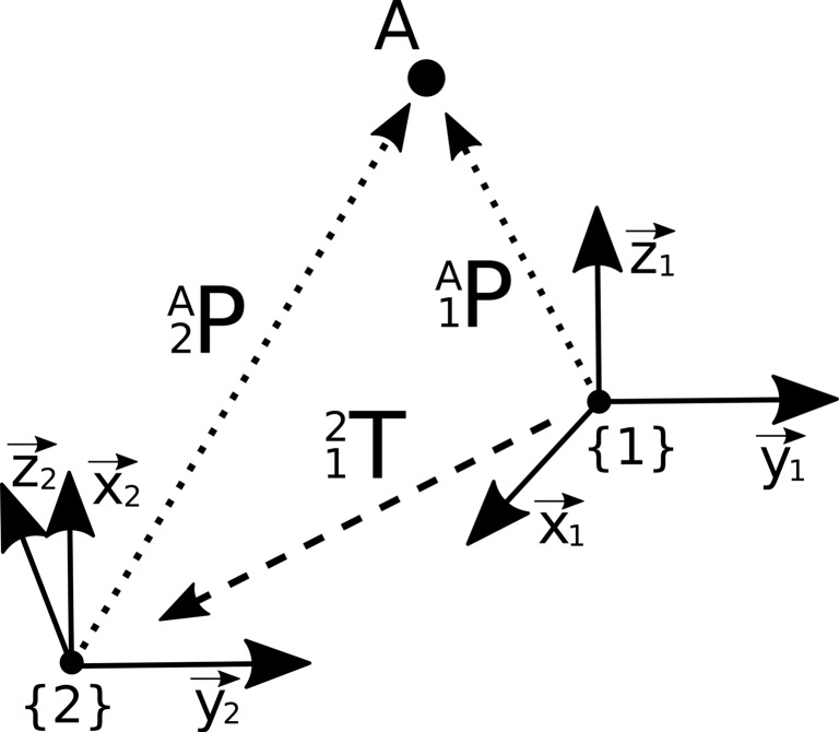
Illustration of a point A, which is described in two different coordinate systems {1} and {2} by respective position vectors and . To obtain the coordinates of point A in the respective other coordinate system, the relative position of the two coordinate systems has to be defined by a transformation matrix T which is then applied by a matrix-vector multiplication
Synchronization of Image Data from the Same Examination
DICOM [3] is a standard container format for medical image data. The live synchronization function of PACS viewing systems uses metainformation called C.7.6.2 Image Plane Module [4] from the DICOM header, which describes the position and orientation of the image data within the patient-based reference coordinate system (RCS). This RCS is a right-handed left-posterior-head (LPH) coordinate system [5]. To create the transformation between the image inherent coordinate system {D} of a three-dimensional single-frame DICOM dataset and the RCS (denoted {W}), the DICOM elements Image Position Patient (0020,0032) (IPP), Image Orientation Patient (0020,0037) (IOP), and Pixel Spacing (0028,0030) (PS) are applied. Figure 2 illustrates how these tags refer to the RCS. IPP is the coordinate of the upper left pixel described in {W} in millimeter. IOP contains direction cosines of the first row and the first column with respect to {W}. The directional cosines in the direction of the slices can be determined by the cross product of the vectors of the row and column direction or from the normalized vector between the IPP entries of the first and last DICOM file of a single-frame dataset. PS contains the physical distance between the voxel centers in row direction and column direction in millimeter. The distance between the voxel centers in slice direction can be determined by the length of the vector between the IPP entries of the first and last DICOM files of a single-frame dataset, divided by the number of frames . Section C.7.6.6.2.1.1 of the DICOM standard [4] holds the formula for calculating the transformation matrix of DICOM image to the RCS. Using the DICOM elements of the Image Plane Module and using the results of the above-described calculations, the transformation matrix between {D} and {W} can established:
| 3 |
Fig. 2.
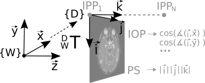
Visualization of the ICS of a DICOM image {D} and the RCS {W}, to which the DICOM image refers. The information of the position, orientation, and scaling of the two systems to each other are stored in the DICOM elements Image Position Patient (IPP), Image Orientation Patient (IOP), and Pixel Spacing (PS). The transformation matrix of the ICS to its RCS is determined by Eq. 3
Note that the first two columns of the transformation matrix are swapped compared to the description in [4] and [6], since we use a programming language with a column-major order (image coordinates in the order row i, column j, slice k). Combining the transformation matrices of two DICOM image datasets yields the direct transformation between between the ICSs, provided the image data refer to the same RCS (cf Fig. 3):
| 4 |
This is the case with image data that was created in a single examination during which the object did not move and the RCS origin was not modified by the operator. For each point A within , the corresponding coordinate in can be calculated by matrix-vector multiplication with the transformation matrix of {D2} to {D1},
| 5 |
where represents the coordinate extended by 1 in the fourth dimension. Figure 4 shows an overlay of two MRI image datasets. The superposition was determined by Eq. 4.
Fig. 3.
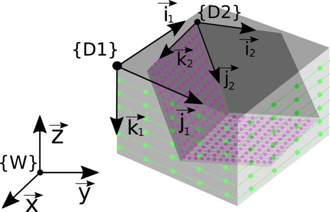
Visualization of two DICOM image datasets {D1} and {D2}, which were acquired during the same examination. They can be synchronized using Eq. 4 as the header information refer to the same reference coordinate system W
Fig. 4.

a Transversal T2-weighted DICOM image. b Sagittal T1-weighted DICOM image. c Overlay of both images. Since the two images were acquired in the same examination, the geometrical information stored in the DICOM header refer to the same RCS {W}. Hence, the superposition could be computed by applying equation (4)
Results
Synchronization of Image Data from Different Examinations
If the DICOM image data originate from different examinations, the datasets cannot be synchronized directly via the DICOM header information. It is irrelevant whether the objects shown were positioned differently in the patient-based RCS at both examinations or the origin of the RCS was set at a different location at the beginning of the two examinations. We assume that DICOM image data from different examinations refer to different RCS {W1} and {W2} as shown in Fig. 5 and therefore cannot be synchronized by Eq. 4:
| 6 |
To enable synchronization in such a case, images from the two examinations must first be registered. Here, the registration problem is the search for the best geometric alignment of two volumetric DICOM series. The two datasets are referred to as fixed image {D1} and moving image {D2}. A common way to solve the registration problem is to optimize a transformation which, when applied to the moving image, aligns the two images best. In the notation used here, this transformation is represented by the transformation matrix between the ICS ; hence, the optimization problem reads
| 7 |
where C represents the cost function, which has a minimum for the optimal alignment of the image datasets, and represents dataset D2 after it has been transformed by . We denote the optimal solution . Since the resulting transformation matrix is only valid for the particular moving image , it cannot be used for synchronizing the view of further datasets of the second examination.
Fig. 5.
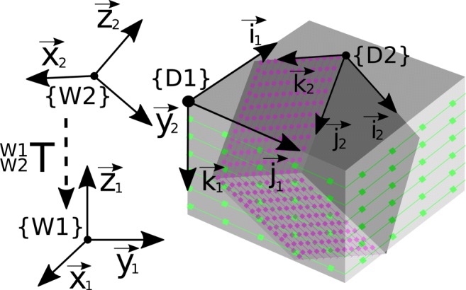
Visualization of two DICOM image data {D1} and {D2}, which were acquired during different examinations. DICOM image data from different examinations refer to different RCS and thus cannot be directly synchronized by Eq. 4
Instead of searching directly for the transformation matrix between the ICS of two images, the aim of the approach described in the following is to find the transformation between the two reference coordinate systems of the two examinations. This procedure has the following advantages:
The scaling of the data is maintained because the registration process inherently includes the corresponding information from the DICOM header.
The transformation between the RCS can be applied to all images {Di} of the second examination; hence, all datasets of two examinations can be synchronized based on only one registration.
To achieve this, the transformation matrix between the two reference coordinate systems is incorporated in the formulation of the registration problem by expressing in dependency on :
| 8 |
A rigid registration can be defined by six parameters, where three parameters represent the rotation and the other three translations. Equation 9 describes one way to define such a transformation between the two RCS, using the cosine (c) and sine (s) of three Z-Y-X Euler angles (φ/𝜃/ψ) and three translations (tx/ty/tz)[7]:
| 9 |
Three-dimensional rotations could alternatively be defined by quaternions, which are very common, e.g., in computer graphics. Quaternions parameterize a rotation by a hypercomplex number which consists of a real part and three imaginary parts. In principle, Euler angles have the disadvantage that certain rotation states can be described by a multitude of angle combinations. This condition is known as gimbal lock. However, when rotation parameters are optimized based on Euler angles, we nevertheless receive a valid solution with the advantage that only three instead of four parameters of rotation have to be optimized.
During the registration process, the similarity between the two image datasets (after applying the transformation to the moving image) has to be determined as explained above. To allow a voxel-by-voxel comparison of the two datasets, the moving image has to be rescaled to the dimension of the fixed image. To do this, each image coordinate from the fixed image is multiplied by the current transformation matrix , which was computed using Eq. 8:
| 10 |
The resulting image coordinates are likely to be non-integer valued so that an interpolation is required. If the coordinates and w lie within the dimension of the moving image, tri-linear interpolation can be applied using the surrounding eight voxels, which we call neighbors . Alternatively, a tri-cubic interpolation could be implemented, which provides better results but at a higher computational expense [8]. If the resulting index is outside the dimension of the moving image, a corresponding voxel value cannot be generated. This voxel is then excluded in the subsequent evaluation of the cost function. The indices of denote the index of row , column , or layer within the moving image, computed from the non-integer image coordinates. A “1” stands for the rounded-up index and “0” for the rounded-down index. Now a corresponding voxel value can be calculated for each , and by tri-linear interpolation:
| 11 |
where is the relative position of the coordinate n in row direction within the neighbors . and are calculated in the same way as . After creation of the transformed and interpolated moving image dataset , the cost function C can be evaluated for the search of ,
| 12 |
where is the transformation matrix defined by Eq. 8 with which the moving image is transformed.
Typical cost functions for intramodal registration (i.e., same contrast, e.g., two T1-weighted datasets) are based on sum of squared differences, sum of absolute differences, or cross correlation [9]. Cost functions for intermodal registration are, e.g., Kulback–Leiber divergence or normalized mutual information [10]. Image preprocessing for optimized automatic registration [11], methods for optimization, and dedicated cost functions [12] are not in the focus of this work.
After optimization, the determined transformation between the two RCS can be used to calculate with which a live synchronization can be performed (see Eq. 5). In the same way, can now be applied for synchronization of all DICOM images {Di} originating from the same examination as the fixed image and all DICOM images {Dj} originating from the same examination as the moving image:
| 13 |
This is possible because image data of a single examination typically refer to the same RCS, as described in Fig. 3. Figure 6 shows a visual demonstration of the synchronization by overlaying image series of two different MRI examinations. For this purpose, a standard intermodal registration of the RCS using normalized mutual information was carried out and the result was applied to two other images originating from the same examination as the moving image. The optimization was performed by the MATLAB function fminunc, a solver for nonlinear programming, which uses the quasi-Newton method followed by a cubic line search.
Fig. 6.

(a) Sagittal 3D T1-weighted dataset and (b) coronar FLAIR dataset. The two image series derive from two different examinations, hence refer to different RCS {W1} and {W2}. Thus, the header information of the DICOM files cannot be used to synchronize the images by Eq. 6 directly (c). After the transformation between {W1} and {W2} has been determined by the registration (d), it can be applied to all image data of the second examination, e.g., coronar (e) or tranaversal T2-weighted images (f)
Discussion
The aim of this project was to present a simple and easy-to-implement approach within the DICOM concept for alignment of DICOM datasets allowing advanced synchronization functions. The proposed registration based on the RCS enables synchronization of all image data from two different examinations based on only one registration. Such functionality can significantly improve the workflow of time demanding comparison of follow-up examinations, since the view can be synchronized not only between different image datasets of a single study (e.g., different MRI sequences) but also between data from different time points. Applying the described concept, the most geometrically robust sequence could be set as default for the automated registration process, e.g., for brain MRIs, high-resolution 3D T1-weighted data sets are well suited, which are often part of standard brain MRI protocols. A big advantage of the proposed approach is that the results of the rigid registration performed on geometrically reliable, typically unimodal image data, can also be transferred to sequences that are more prone to artifacts like diffusion-weighted images (DWI). Due to geometrical instabilities, images of that type could otherwise not be registered on a image to image basis.
The described processing steps could also be applied for automated generation of perfectly aligned slices by mutli-planar reconstructions, provided the spatial resolution of the image data is sufficient. To the best of our knowledge, current PACS systems do not offer such functionality but only provide a point-to-point synchronization. This is suboptimal, e.g., for synchronized scrolling through two transversal sequences that where acquired at slightly different angles.
Furthermore, the described concepts of registration and interpolation are also of value for various scientific applications. If the transformation between images is known by registration, ROI, seed points for segmentation, or segmentation results can be transferred easily between different datasets. For example, a manually or automatically defined volume mask of a tumor can be transferred between the images in order to analyze it multiparametrically in a quantitative way. Furthermore, the transfer of volumes of interests (VOIs) between different image datasets can contribute to the collection of training data for machine-learning purposes [13]. In machine-learning applications, typically all image data have to be aligned and resampled to a unique resolution and orientation. In a well-known challenge in the field of machine learning in medical imaging, namely Brain Tumor Image Segmentation Challenge (BraTS) [14], this is already done prior to the publication of the datasets. The multiparametric MRI datasets available to the participants for training and validation are aligned, resampled to a standard resolution, and stored in a research data format. Our manuscript may serve as a guide on how to generate such aligned training data staying within the DICOM framework. All necessary steps from registration to interpolation are described. The presented method of registration within the RCS could accelerate the creation of such a collection of aligned image data. PACS system viewers could be expanded by a function that allows creation and export of image data for machine-learning applications directly from DICOM data. Lastly, also integration of machine-learning tools into PACS viewing systems requires corresponding data processing.
As a limitation of this work, only rigid registration was considered. The assumption of rigid objects should be valid in case of brain examinations but may be violated in other body areas. This however is also an issue when synchronizing image data of a single examination, e.g., when the bladder fills up during a prostate examination. However, based on our experience, synchronization appears to be of value also in case of movement and nevertheless eases navigation through multi-parametric datasets. Moreover, the results of a rigid registration may provide a good starting point for non-rigid, deformable registration applying locally applied transformations on top [15, 16].
Conclusion
In this project, we presented a method that allows alignment and synchronization of DICOM image data from different examinations. The in-depth explanation and illustration of the required processing steps is potentially also helpful for development of other applications in the field of medical image analyses.
Contributor Information
Sebastian Nowak, Email: snowak1@hs-koblenz.de.
Alois M Sprinkart, Email: sprinkart@uni-bonn.de.
References
- 1.Haak D, Page C-E, Deserno TM: A survey of DICOM viewer software to integrate clinical research and medical imaging. J Digit Imaging 29.2: 206–215, 2016 [DOI] [PMC free article] [PubMed]
- 2.Grood ES, Suntay WJ: A joint coordinate system for the clinical description of Three-Dimensional motions: Application to the knee. ASME. J Biomech Eng 105 (2): 136–144, 1983. 10.1115/1.3138397 [DOI] [PubMed]
- 3.NEMA PS3 / ISO 12052, Digital Imaging and Communications in Medicine (DICOM) Standard, National Electrical Manufacturers Association, Rosslyn, VA, USA (available free at http://medical.nema.org/), 2018
- 4.National Electrical Manufacturers Association: Digital Imaging and Communications in Medicine (DICOM) Part 3: Information Object Definitions: 7.6.2 Image Plane Module, 2011, pp 408– 410
- 5.National Electrical Manufacturers Association:Digital Imaging and Communications in Medicine (DICOM) Part 3: Information Object Definitions : 3.17.1 Reference Coordinate System, 2011, p 55
- 6.Xiangrui L, Morgan PS, Ashburner J, Smith J, Rorden C: The first step for neuroimaging data analysis: DICOM to NIfTI conversion. J Neurosci Methods 264: 47–56, 2016 [DOI] [PubMed]
- 7.Gan J, Oyama E, Rosales E, Hu H: A complete analytical solution to the inverse kinematics of the Pioneer 2 robotic arm. Robotica 23: 123–129, 2005. 10.1017/S0263574704000529
- 8.Ostuni JL, Santha AK, Mattay VS, Weinberger DR, Levin RL, Frank JA: Analysis of interpolation effects in the reslicing of functional MR images. J Comput Assist Tomogr 21 (5): 803–810, 1997 [DOI] [PubMed]
- 9.Medical image registration. In: (Hajnal J, Hill DLG, Hawkes DJ, Eds.) Boca Raton: CRC Press, 2001
- 10.Pluim JPW, Antoine Maintz JB, Viergever MA Mutual-information-based registration of medical images: a survey. IEEE transactions on medical imaging, 2003, pp 986–1004 [DOI] [PubMed]
- 11.Malinsky M, Peter R, Hodneland E, Lundervold J., Lundervold A, Jan J: Registration of FA and T1-Weighted MRI data of healthy human brain based on template matching and normalized Cross-Correlation. J Digit Imaging 26: 774–785, 2013 [DOI] [PMC free article] [PubMed]
- 12.Jenkinson M, Bannister P, Brady M, Smith S: Improved optimization for the robust and accurate linear registration and motion correction of brain images. NeuroImage 17: 825–841, 2002. 10.1006/nimg.2002.1132 [DOI] [PubMed]
- 13.Hoseini F, Shahbahrami A, Bayat P An efficient implementation of deep convolutional neural networks for MRI segmentation j digit imaging, 2018. 10.1007/S10278-018-0062-2 [DOI] [PMC free article] [PubMed]
- 14.Menze Bjoern H, et al. The multimodal brain tumor image segmentation benchmark (BRATS). IEEE transactions on medical imaging 34.10, 2015, pp 1993–2024 [DOI] [PMC free article] [PubMed]
- 15.Glocker B, Sotiras A, Komodakis N, Paragios N: Deformable medical image registration: setting the state of the art with discrete methods. Annu Rev Biomed Eng 13: 219–244, 2011 [DOI] [PubMed]
- 16.Schnabel JA, Rueckert D, Quist M, Blackall JM, Castellano-Smith AD, Hartkens T, Gerritsen FA: A generic framework for non-rigid registration based on non-uniform multi-level free-form deformations.. In: International Conference on Medical Image Computing and Computer-Assisted Intervention. Springer, Berlin, 2001, pp 573–581