

Abstract
Poly(3,4-ethylenenedioxythiophene) or PEDOT is a promising candidate for next-generation neuronal electrode materials but its weak adhesion to underlying metallic conductors impedes its potential. An effective method of mechanically anchoring the PEDOT within an Au nanorod (Au-nr) structure is reported and it is demonstrated that it provides enhanced adhesion and overall PEDOT layer stability. Cyclic voltammetry (CV) stress is used to investigate adhesion and stability of spin-cast and electrodeposited PEDOT. The Au-nr adhesion layer permits 10 000 CV cycles of coated PEDOT film in phosphate buffered saline solution without delamination nor significant change of the electrochemical impedance, whereas PEDOT coating film on planar Au electrodes delaminates at or below 1000 cycles. Under CV stress, spin-cast PEDOT on planar Au delaminates, whereas electroplated PEDOT on planar Au encounters surface leaching/decomposition. After 5 weeks of accelerated aging tests at 60 °C, the electrodeposited PEDOT/ Au-nr microelectrodes demonstrate a 92% channel survival compared to only 25% survival for spin-cast PEDOT on planar films. Furthermore, after a 10 week chronic implantation onto mouse barrel cortex, PEDOT/Au-nr microelectrodes do not exhibit delamination nor morphological changes, whereas the conventional PEDOT microelectrodes either partially or fully delaminate. Immunohistochemical evaluation demonstrates no or minimal response to the PEDOT implant.
Keywords: chronic, electrodes, gold nanorods, PEDOT, stability
1. Introduction
In the past decade, conducting polymers (CPs) have gained substantial attention as the direct interfacing material between biomedical devices and neural tissue due to their superior electrochemical properties compared to conventional metals such as Au, Pt, and Ir.[1] In particular, poly(3,4-ethylenedioxythiophene):poly(styrenesul fonate) (PEDOT:PSS) has emerged as an outstanding material for neural interfaces and biomedical applications including recording and stimulating neural activity, neural regeneration, and therapeutic drug delivery.[1a,e,2] This is afforded with PEDOT:PSS due to several promising features such as low electrochemical impedance for high signal-to-noise ratio (SNR) recording, high charge injection capacity for safe and efficient stimulation, and compliant (soft) mechanical properties for conforming to biological tissue.
Despite the superior properties, exploiting the full capability of CP coatings in chronic biomedical applications has been limited due to their weak adhesion and mechanical stability driven by i) lack of strong covalent bonds between coated polymer layers and underlying noble metal conductors[3] and ii) the volumetric expansion and contraction of polymer coatings in physiological media.[4] As a result of the poor adhesion, cracks in the CP films or complete delamination from the underlying metal conductors are often observed during 1) in vitro aging experiments, 2) chronic implants, 3) prolonged charge injection, and 4) mechanical stresses driven by sterilization.[5] In vivo chronic implantation of PEDOT:PSS-coated electrodes resulted in a loss of conductivity/functionality of the device attributed to the mechanical failure of polymer coating.[3b,5b,6] Different groups have attempted to find a method of extending the operating lifetime of the polymer-based systems. Two approaches emerged to tackle this problem. The first approach is chemical in nature and utilizes an intermediate functionalized monolayer/organic molecule between PEDOT and the underlying metal conductor through formation of covalent bonds between the intermediate layer and both sides, PEDOT and the underlying metal conductor. One such approach involves electrografting amine-functionalized EDOT[7] to stabilize PEDOT on metallic conductors which was subjected to 1 h of ultrasonication without significant cracking or delamination, whereas untreated PEDOT delaminated within seconds. However, cyclic voltammetry (CV) stability tests affected the treated PEDOT coating and the electrochemical impedance showed a significant degradation after 300 CV cycles.[8] The second approach is physical in nature and employs mechanical interlocking and more engaged surface area (roughened substrate) to anchor the coated CP to underlying metals. “Fuzzy gold” stabilization for polypyrrole (PPy)[9] and laser-roughened Pt anchoring for PEDOT/p-toluenesulfonate (pTS) and PEDOT/ ClO4 are examples of the mechanical anchoring approach. When the latter was employed for PEDOT:PSS, severe delamination occurred upon biphasic pulsing (864 million pulses at 70 µC cm−2) or steam sterilization.[5b] Recently, Boehler et al. demonstrated sputtered iridium oxide film (SIROF) as an exceptional adhesion promoter layer for electrodeposited PEDOT coatings on macroscale electrodes (500 µm diameter), resulting in polymer survival for over 10 000 CV cycles and 110 days under accelerated aging conditions at 60 °C.[10] The efficacy of this approach for microscale PEDOT-coated electrodes and for spin-cast PEDOT – used recently in recording for the surface of human cortex[11] – is yet to be assessed for this technique.
Here, we report an alternative approach to improve the adhesion of the polymer on underlying metal conductors, using a gold nanorod (Au-nr) layer. We conducted different electrochemical tests including CV, electrochemical impedance spectroscopy (EIS) along with morphological characterizations (optical, focused-ion beam (FIB), and scanning electron microscopy (SEM)) to fully characterize the fabricated electrodes and examine the PEDOT:PSS/Au-nr surface/interface. The Au-nr structure was integrated on top of the conventional Au electrodes, using a dealloying technique,[12] capable of enhancing the adhesion of spin-cast and electrodeposited PEDOT:PSS films. To benchmark the stability of modified PEDOT:PSS electrodes against conventional planar electrodes, we applied extensive CV stressing cycles (over 10 000) to validate the anchoring capability of the Au-nr layer. We hypothesize that the Au-nr interlocking layer prevents the delamination of PEDOT film under long-term reversible charge injections (cycling tests) where induced volumetric contraction/expansion of polymer film is possible as the result of electrostatic repulsions between fixed positive charges and exchange of cations, anions, and solvent molecules between the polymer and the solution.[13] The Au-nr layer stabilized the PEDOT:PSS/Au-nr interface for over 10 000 stressing CV cycles, affording at least 20-fold more cycling of coated polymer compared to that of conventional spin-cast PEDOT:PSS on planar Au macroelectrodes with the same diameter of 500 µm for which delamination occurred only after only 500 cycles. Additionally, we investigated the efficacy of the Au-nr films on the stability of 50 µm diameter electrodes, important for high spatial resolution in recording and stimulating electrodes. Within microscale, a 50 µm PEDOT:PSS/Au-nr electrode passed 8000 CV cycles without significant morphological change or electroactivity loss, yielding a tenfold improvement given the only 800 cycles’ survival for PEDOT:PSS on planar Au. In addition, we observed a different degradation mechanism for spin-cast PEDOT:PSS compared to electrodeposited PEDOT:PSS film under cycling stress that is not discussed in earlier literature. We found that under CV stress experiments, the spin-cast PEDOT:PSS film tends to delaminate from the metal substrate, exhibiting stronger cohesive polymer film strength than that of the polymer/metal interface, whereas electrodeposited PEDOT film tends to leach out via surface decomposition and gradual thinning rather than delaminating from the substrate. To simulate a 6 month semi-chronic implant, accelerated aging tests (passive test) were performed to expose the electrodes to wetting environment over a long time (5 weeks) at 60 °C and longer survival of the coating was observed using the Au-nr structures. The adhesion-promoting effect of Au-nr layer was also validated in vivo where after 10 weeks chronic implant onto mouse barrel cortex, the PEDOT:PSS did not detach from the Au-nr substrate, in contrast to planar Au electrodes which were either partially or fully delaminated. In addition, the biocompatibility of PEDOT:PSS/ Au-nr electrodes was verified through immunohistochemistry that showed no neuronal loss and minimal activation of astrocytes and microglia at the implant site.
2. Results
PEDOT:PSS electrodes were fabricated according to published procedures utilizing a thin film of Cr/Au layer with 15/100 nm thickness as metallic leads and conductors. The entire device is sandwiched in between 2 µm upper and 2 µm lower parylene C layers except where the PEDOT:PSS film is coated.[1b,14] The Au-nr layer was selectively patterned in regions where PEDOT:PSS was to be coated. To realize the Au-nr film, a dealloying process of the AuAg alloy and preferential etching of Ag[12a] was performed in a nitric acid solution, as detailed in the Experimental Section. The structural difference of the Au-nr film compared to typical nanoporous Au films resulting from the dealloying process are presented in Figure S1 (Supporting Information). To benchmark the electrochemical performance of Au-nr and planar Au (Au-pl) contacts, we prepared electrodes with 50 and 500 µm[15] diameters, which we refer to as micro and macro hereafter. Figure 1a,b shows the optical images of the fabricated Au-nr and Au-pl macroelectrodes with their corresponding cross-sectional schematics, respectively. The darker color of Au-nr electrodes under optical imaging distinguishes them from Au-pl contacts due to light trapping in the nanoporous structure.
Figure 1.
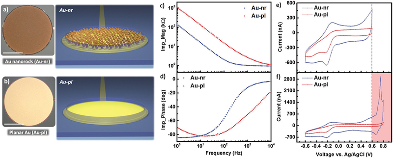
Au nanorods (Au-nr) versus planar Au (Au-pl) electrodes. Top view optical image and corresponding cross-sectional schematic of a) Au-nr and b) Au-pl macroelectrodes with 500 µm diameter (scale bar, 200 µm). Measured c) magnitude and d) phase of the electrochemical impedance spectroscopy (EIS) of Au-nr (blue) and Au-pl (red) electrodes for the frequency range of 1 Hz–10 kHz, showing enhanced electrochemical property of Au-nr compared to Au-pl electrode due to the larger interface capacitance (double-layer). e) Measured cyclic voltammetry (CV) of Au-nr (blue) and Au-pl (red) electrodes within −0.6–0.6 V versus Ag/AgCl potential limits, showing larger CV curve for Au-nr contact (larger CSC). f) Measured CV of Au-nr (blue) and Au-pl (red) electrodes within −0.6–0.8 V versus Ag/AgCl potential limits, demonstrating large oxidation current peak at around 0.7 V versus Ag/AgCl. Therefore, cycling potentials beyond 0.6 V (red-colored regime) are excluded from stability tests to operate the electrodes within the safe electrochemical limits.
EIS was performed to characterize and understand the Au-nr and Au-pl electrochemical properties. Measured EIS within the frequency range of 1 Hz to 10 kHz is shown in Figure 1c,d which demonstrates lower magnitude for the elec-trochemical impedance of the Au-nr electrode for the whole frequency range compared to that of Au-pl contact. For Au-nr electrodes and at frequencies higher than 300 Hz, the imped-ance becomes limited with the series resistance Rs, as deduced from the negligible dependence on frequency beyond 300 Hz and a rapid increase of the phase from −90° to 0°. At these frequencies, the reactance due to the large double layer capaci-tance is lower than Rs. The lower capacitance and higher reactance of the Au-pl electrode delays such transition by one decade of frequency up to 3 kHz. CV is the standard practice to gain insights into the electrochemical reactions, presence of electroactive elements, and stability of the electrode.[1d] Measured CVs of Au-nr and Au-pl electrodes between potential limits of −0.6 and 0.6 V, in phosphate buffered saline (PBS) at 100 mV s− 1, are depicted in Figure 1e. As expected, the Au-nr contact exhibited larger charge storage capacity (CSC) equal to 3.08 mC cm−2 compared to that of the Au-pl electrode (1.4 mC cm−2) due to the larger double-layer charging capacity at the electrode/electrolyte interface. The small signal components for different electrodes are extracted from equivalent circuit models and are provided in Figure S2 (Supporting Information). Earlier works reported −0.6–0.8 V (in reference to Ag/AgCl) scan window as the safe potential limits or water limit for CV cycling of common metal electrodes such as Pt and Ir.[1d] However, we found out that this typical water window (−0.6–0.8 V vs Ag/AgCl) is not suitable for cycling the Au-nr electrodes due to the emergence of a significant oxidation peak at ≈0.7 V versus Ag/AgCl (Figure 1f). To avoid the oxidation current peak as a potential degrading factor in our PEDOT:PSS stability tests, we restricted the CV cycling window to −0.6–0.6 V versus Ag/AgCl for all CV experiments performed in this work. CV stressing of the Au-nr electrode in the potential window of −0.6–0.6 V has shown that the Au-nr electrode itself is stable, as demonstrated in Figure S3 (Supporting Information).
Optical microscope pictures throughout the fabrication process are shown in Figure 2. For the fabrication of the PEDOT:PSS/Au-nr device, the AuAg alloy film was deposited selectively on electrode sites. A dealloying step then follows to realize the Au-nr structures on sensing sites; sequence of metallic film definitions are shown in Figure 2a. Passivation layer deposition and opening windows in parylene C above the electrode sites then follow and finally the microfabrication is completed with PEDOT:PSS deposition either through electrodeposition or spin-cast technique. The final PEDOT:PSS/ Au-nr device as detached from the glass carrier substrate is shown in Figure 2b (fabrication flow is presented in the Figure S4 in the Supporting Information). Anisotropic conductive film (ACF) bonding was used to connect the device to commercial off the shelf ribbon cables that fit in the external characterization circuitry. The electrode arrays contain both macro- and microscaled electrodes which allowed us to investigate device stability for different diameters. In this stability study, only one macrosize (D = 500 µm) and microsize (D = 50 µm) electrodes were tested. The top view optical image of the patterned/dealloyed Au-nr film on 50 µm diameter electrode is shown in Figure 2c along with an SEM image of Au-nr structure. After deposition of the parylene C passivation layer, openings on top of electrode sites were realized using oxygen plasma etching, as shown in Figure 2d, followed by PEDOT:PSS deposition using either spin-coating or electroplating method. An optical microscope image of the spin-coated PEDOT:PSS microelectrode using spin-cast processing is shown in Figure 2e. To confirm the structural integrity of the PEDOT:PSS/underlying Au-nr and Au substrate/parylene C interfaces, we performed FIB slicing at the center of the microdot of Figure 2e. The con-finement of the PEDOT:PSS layer in the 3D Au-nr structure is demonstrated in the SEM image of Figure 2f, highlighting the intimate contact between the different layers of the device.
Figure 2.

Structural and morphological characterization of the PEDOT:PSS/Au-nr electrophysiology device. a) A picture of the neural probe on glass carrier substrate at different sequential steps of Cr/Au metallization, AuAg alloy deposition and Au-nr film formation using dealloying technique, from left to the right, respectively. b) A picture of the flexible/conformal PEDOT:PSS/Au-nr neural probe on parylene C released from glass substrate and bonded to ACF/ribbon cables to connect to the external characterization circuitry; the inset shows the macro-/microarray layout including the 50 and 500 µm diameter electrodes assessed in this study (scale bar, 1 mm). Fabrication flow of the 50 µm PEDOT:PSS/Au-nr electrode including c) Au-nr adhesion layer definition on sensing site (adjacent top view SEM image shows morphology of the nanostructures of Au-nr film), d) selective etching of the parylene C layers (abbreviated as pxc) on top of the metal contact, and e) deposition of the PEDOT:PSS layer using spin-coating/peeling-off technique. f) Tilted view SEM image showing the cross-section of the stacked layers highlighting the intimate contact between the different layers of the device; sandwiched in between the parylene C and PEDOT:PSS films are the only electrochemical interfaces.
The −0.6–0.6 V versus Ag/AgCl CV cycling window discussed above was used to characterize the adhesion and mechanical stability of the PEDOT:PSS on Au-nr and Au-pl, at a scan rate of 0.1 V s−1. The electrochemical impedance (1 Hz–10 kHz) and electrode surface alteration, as determined by optical microscope imaging, were monitored periodically during CV measurements to assess the adhesion and stability of the PEDOT:PSS coating on different underlying metal substrates. The PEDOT:PSS film was deposited potentiostatically on the Au-nr electrode with a 500 µm diameter. Figure 3a shows the intact electrode prior to cycling, highlighting the uniform electrodeposited PEDOT:PSS film over the entire Au-nr electrode surface.
Figure 3.

Electrodeposited PEDOT:PSS/Au-nr and PEDOT:PSS/Au-pl macroelectrode stability tests under cycling stress. Optical images of the same PEDOT:PSS/Au-nr macrodot (D = 500 µm); a) as-fabricated and after sequential b) 3000, c) 7000, and d) 11 000 CV cycles, highlighting the progressive colorimetric change of polymer coating (scale bar, 100 µm). e) Tilted cross-sectional SEM images of the PEDOT:PSS coating on the as fabricated Au-nr substrate. The PEDOT layer above the surface of the Au-nrs obstruct a clear view of the Au-nr tips. f) Tilted cross-sectional SEM images of the PEDOT:PSS coating on Au-nr substrate after 11 000 cycles. The tips of the Au-nrs are sharper in (f) compared to (e), indicating slight thinning effect of cycling stress on polymer thickness, while the bulk of the polymer film still is retained within the 3D structure of the Au-nr film. g) Impedance magnitude and phase spectra of the PEDOT:PSS coating on Au-nr substrate; as-deposited and CV cycled for 1000, 3000, 5000, 7000, 10 000, and 11 000 cycles, showing the nearly fixed EIS spectra up to 10 000 CV cycles. Significant electrochemical changes were measured (purple traces in EIS spectra) after 11 000 CV cycles at which metal leads failure was observed (inset). Optical images of the same PEDOT:PSS/Au-pl macrodot (D = 500 µm); h) as-fabricated and after sequential i) 1000, j) 2000, and k) 2500 CV cycles, highlighting noticeable progressive colorimetric change of polymer coating under cycling stress (scale bar, 100 µm). Tilted view cross-sectional SEM images of PEDOT:PSS film on Au-pl substrate; l) as-deposited and m) after 2500 CV cycles, revealing a severe delamination of the PEDOT:PSS film from underlying metal substrate (indicated by the “Gap”). n) Impedance magnitude and phase spectra of the PEDOT:PSS coating on Au-pl substrate; as-deposited and after being CV cycled for 200, 500, 800, 1200, 1500, 2000, and 2500 cycles, showing noticeable impedance change, with an up to tenfold (10×) increase in magnitude at 1 Hz after 2500 CV cycles.
Optical inspection of the same electrode of Figure 3a indicates the gradual change in the polymer color (colorimetric change) under CV stressing, as shown in optical images of Figure 3b–d which correspond to 3000, 7000, and 11 000 CV cycles, respectively. This progressive color change can indicate overoxidation of the PEDOT:PSS film which can occur during irreversible electrochemical oxidation reactions[10,16] rather than being related solely to the stability failure or detachment of the PEDOT:PSS coating. However, neither significant delamination nor severe cuts across the electrode surface were observed over the entire cycling test period (over 10 000 cycles). To validate the stability of the interface and absence of delamination, we performed FIB slicing at the center of a reference macrodot that did not undergo any CV cycling (Figure 3e) and at the center of a macrodot shown in Figure 3a–d after 11 000 cycling tests (Figure 3f). The 45° tilted view SEM images indicate a slight thinning of the polymer thickness over the course of cycling/ charge injection; nevertheless, the bulk of the PEDOT:PSS film was still retained within the 3D nanostructure of the Au-nr conductor without any sign of delamination. The electrochemical impedance magnitude and phase of the PEDOT:PSS/Au-nr macroelectrode, as-fabricated and after being CV cycled for 1000, 3000, 5000, 7000, 10 000, and 11000 cycles, are shown in Figure 3g. The measured EIS spectra were nearly identical for the as-fabricated versus up to 10 000 CV cycles. A slight upward shift of the impedance traces below 40 Hz can be attributed to a slight decrease in the PEDOT:PSS thickness (color change in Figure 3a–d and additional transparency under electron beam on top of the Au-nr array in SEM, Figure 3e,f) which reduces the capacitance and increases the electrode impedance. At and above 11 000 CV cycles, we observed an increase in the series resistance manifested by an upshift of the impedance plateau at high frequencies, as shown with the purple trace in Figure 3g. This result was counterintuitive because any morphological changes for the PEDOT:PSS, such as the thinning process illustrated in Figure 3e,f should result in a change of the electrode capacitance or Faradaic impedance. To investigate the origin of the increase in the series resistance, we inspected the overall device morphology and observed a partial dissolution of the Au metal lead, as illustrated in the inset optical image of Figure 3g. This phenomenon of Au electrode dissolution was observed with multiple device experiments and is likely due to the local exposure of the Au surface during oxide formation/reduction as well as oxygen evolution upon cycling voltammetry.[17] Therefore, to exclude the effect of metal lead dissolution from our PEDOT:PSS stability study, a maximum count of 10 000 CV cycles was set as the end point of the adhesion test protocol.
As a control experiment for the enhanced stability of PEDOT:PSS/Au-nr, PEDOT:PSS was also electrodeposited on planar Au conductors (PEDOT:PSS/Au-pl) with 500 µm diameter, as shown in Figure 3h. A similar color alteration of the polymer was observed across the PEDOT:PSS/Au-pl electrode surface over the course of cycling tests, as shown in optical images Figure 3i–k after CV cycles of 1000, 2000, and 2500 cycles, respectively. However, after 2500 CV cycles, PEDOT:PSS/Au-pl electrodes experienced a severe polymer film delamination near the electrode edge. For further examination, FIB slicing was performed on both a reference electrode that did not undergo CV cycling and the electrode of Figure 3k that underwent 2500 CV cycles. The cross-section of the reference electrode in Figure 3l displayed an intact interface between the PEDOT and the underlying planar Au conductor. However, the cross-section of the 2500 CV–cycled electrode displayed a clear gap and detachment with the underlying Au conductor, as shown in Figure 3m, and is in agreement with the wrinkled morphology observed in the optical image of Figure 3k that we associated with PEDOT delamination. Additionally, the electrode degradation under cyclic load for PEDOT:PSS/Au-pl is manifested in a progressive increase in the impedance magnitude and shift in impedance phase of Figure 3n with increasing cycling counts, in contrast to the nearly stable spectra of the PEDOT:PSS/Au-nr. The magnitude of the impedance at 1 Hz increases by tenfold after 2500 CV cycles.
Another method for depositing PEDOT:PSS from solution is the spin-coating technique that offers monolithic integration and scalability benefits over electrodeposited PEDOT and has been recently used in high-density neural probe electrophysiology.[1b,11a,18] We characterized the stability of spin-cast PEDOT:PSS film on the 500 µm diameter conductor (Figure 4a, see the Experimental Section) in a similar experimental convention to electrodeposited PEDOT:PSS. Figure 4b–h demonstrates a surface morphology change of the same PEDOT:PSS/Au-nr electrode at different CV cycles (up to 11 000 cycles). Similar to the electrodeposited PEDOT:PSS, progressive alteration of the PEDOT:PSS color was apparent under electrochemical stress by showing rapid changes during the first 3000 cycles’ course (Figure 4d). It should be noted that after 7000 cycles (Figure 4f), the contact interface between the PEDOT and the underlying Au-nr layer rearranges, presumably due to volumetric changes, resulting in strong color changes particularly at the dot edges (see Figure 4g,h). Inspection by SEM (Figure S5, Supporting Information) showed a completely intact PEDOT film that has wrinkles in some regions of the dot that are elevated above the dot’s surface. Despite the partial delamination of polymer coating, the magnitude and phase of the EIS spectra (Figure 4l) exhibit identical characteristics during the entire test period up to 10 000 CV cycles without noticeable electrochemical degradation, indicating a stable condition of spin-coated PEDOT:PSS/Au-nr macroelectrode under cycling stress. Similar to electrodeposited PEDOT:PSS/Au-nr contacts (Figure 3g), significant EIS changes observed at or above 11 000 cycles, shown as purple traces in Figure 4l, were confirmed with inspection by optical microscope as the result of wiring failure rather than being related solely to the polymer stability. In contrast to the PEDOT:PSS/Au-nr electrode, the PEDOT:PSS/Au-pl contact (Figure 4i) showed delamination from the planar Au conductor starting from the electrode edges at only 500 CV cycles, as shown in Figure 4j. PEDOT:PSS/Au-pl macroelectrode undergoes a full detachment from the substrate at 1000 CV cycles (Figure 4k), as can also be observed with the noticeable impedance shifts in EIS spectra of Figure 4m. These results suggest at least tenfold improvement in the adhesion of spin-coated PEDOT:PSS/Au-nr which endured 10 000 CV, as discussed above. Electrodeposited PEDOT coating on Au-nr substrates (Figure 3) did show a slight EIS variation over the course of 10 000 CV cycles, but no sign of film delamina-tion from the substrate was observed. In contrast, spin-coated PEDOT film on Au-nr substrates (Figure 4) demonstrated partial film detachment due to cycling stress but fully stable electrochemical characteristics noted by measuring identical EIS spectra upon 10 000 CV cycles. From these experiments, we found that the adhesion of the PEDOT:PSS on Au-nr film is the strongest with electrodeposition (Figure 3a–f) compared to spin-coating (Figure 4a–h). We also found that the electrodeposited PEDOT:PSS on Au-nr film underwent a slight thinning process that we associated with a slight reduction of the capacitance and increase in the impedance (Figure 3g). The fixed electrochemical impedance spectra for spin-cast PEDOT:PSS/Au-nr microelectrode indicate absence of such thinning and stronger cohesive forces in the PEDOT film. We also found that the adhesion of electrodeposited PEDOT:PSS on planar Au conductors (Figure 3h–k) is stronger than that of spin-cast films (Figure 4i–k).
Figure 4.

Spin-coated PEDOT:PSS/Au-nr and PEDOT:PSS/Au-pl macroelectrode stability tests under cycling stress. Optical images of the same spin-coated PEDOT:PSS/Au-nr macrodot (D = 500 µm); a) as-fabricated and after sequential b) 500, c) 1300, d) 3000, e) 5000, f) 7000, g) 10 000, and h) 11 000 CV cycles, highlighting the progressive colorimetric change of polymer coating along with partial PEDOT:PSS film delamination upon CV cycling, happening at or above 7000 CV cycles. Optical images of the same spin-coated PEDOT:PSS/Au-pl macrodot (D = 500 µm); i) as-fabricated and after sequential j) 500, k) 1000 CV cycles, demonstrating partial and complete PEDOT film delamination, respectively (scale bars are 125 µm). l) The measured magnitude and phase impedance spectra of the PEDOT:PSS/Au-nr macroelectrode at different cycling states; as-fabricated and CV cycled for 500, 1300, 3000, 5000, 7000, 10 000, and 11 000 cycles, which correspond to the left side optical images. The purple traces show the measured EIS spectra of electrode after 11 000 CV cycles, indicating a noticeable impedance change due to the wiring failure at that cycle count. m) The measured magnitude and phase impedance spectra of the PEDOT:PSS/Au-pl macroelectrode; as-fabricated (black) and CV cycled for 500 (dark-red) and 1000 (light-red) cycles, demonstrating obvious impedance shifts due to the partial and complete PEDOT film delamination upon charge injection.
We have focused so far on large diameter (0.5 mm) electrodes, consistent with earlier studies on improving the adhesion strength and stability of PEDOT.[8,10,19] But microelectrodes are desired for advancing neurophysiological recordings both from the surface and the depth of brain tissue in a chronic setting.[11a,20] Therefore, we evaluated the stability of PEDOT:PSS films on 50 µm diameter Au-nr (Figure 5a) and Au-pl (Figure 5i) microelectrodes. For spin-cast PEDOT:PSS/ Au-nr, the microelectrodes display an earlier onset of color change (>1000 cycles, Figure 5c) compared to the macroelectrodes (>3000 cycles, Figure 3c). While this color change was notable but not dramatic for macroelectrodes (11 000 cycles, Figure 3d), a dramatic color change (>2000 cycles, Figure 5c–h) and PEDOT delamination from the microelectrode edge (>5000 cycles, Figure 5e–h) prevailed. Despite these morphological changes, the corresponding magnitude and phase of the EIS spectra measured after different CV cycling intervals (Figure 5l) did not indicate a significant electrochemical degradation of the electrode up to 8000 cycles. However, at 9000 CV cycles, a significant shift in EIS spectra was measured, as illustrated with the purple traces in Figure 5l, which we attribute to wiring failure as we discussed above. On the other hand, PEDOT:PSS/Au-pl microelectrode exhibited a relatively compromised stability upon CV cycling that was evident from the ring-shaped delamination in the optical images of Figure 5j,k after only 400 and 800 CV cycles, respectively. In addition, significant electrochemical degradation is perceptible from the impedance magnitude and phase spectral shifts, as shown in Figure 5m by dark-red (after 400 CV cycles) and light-red (after 800 CV cycles) traces. Nevertheless, the Au-nr anchoring layers also offer a stabilizing capability for microelectrodes by offering at least tenfold enhanced durability for the PEDOT:PSS/Au-nr compared to PEDOT:PSS/Au-pl microelectrode. The mechanistic electrochemical studies discussed above elucidated the success of Au-nr conductors for stabilizing PEDOT:PSS under electrochemical stress. Another test that must be passed is the durability of the PEDOT:PSS in wet mediums that can be characterized with accelerated aging and in vivo experiments. We performed both types of experiments. Venkatraman et al.[19] have shown that PEDOT:PSS/Pt macroelectrodes were stable after an accelerated aging test in PBS for 5 weeks, whereas the microelectrodes experienced a significant degradation after 4 weeks.
Figure 5.

Spin-coated PEDOT:PSS/Au-nr and PEDOT:PSS/Au-pl microelectrode stability tests under cycling stress. Optical images of the same spin-coated PEDOT:PSS/Au-nr microdot (D = 50 µm); a) as-fabricated and after sequential b) 1000, c) 2000, d) 3000, e) 5000, f) 7000, g) 8000, and h) 9000 CV cycles, highlighting the progressive colorimetric change of polymer coating along with partial PEDOT:PSS film delamination upon CV cycling, happening at or above 5000 CV cycles. Optical images of the same spin-coated PEDOT:PSS/Au-pl microdot (D = 50 µm); i) as-fabricated and after sequential j) 400, k) 800 CV cycles, demonstrating ring-shaped PEDOT film delamination and its expansion, respectively (scale bars are 15 µm). The measured magnitude and phase impedance spectra of the PEDOT:PSS/Au-nr microelectrode at different cycling states; as-fabricated and CV cycled for 1000, 2000, 3000, 5000, 7000, 8000, and 9000 cycles, which correspond to the left side optical images. The purple traces show the measured EIS spectra of electrode after 9000 CV cycles, indicating a noticeable impedance change due to the wiring failure at that cycle count. m) The measured magnitude and phase impedance spectra of the PEDOT:PSS/Au-pl microelectrode; as-fabricated (black) and after different cycling states of 400 (dark-red) and 800 (light-red) CV cycles, which demonstrate obvious impedance shifts due to the ring-shaped PEDOT film delamination upon charge injection.
Given this and the interest in microelectrodes for electrophysiology applications, we performed accelerated aging experiments on microelectrode arrays with D = 50 µm that were prepared with spin-coated and electroplated PEDOT:PSS on both Au-nr and Au-pl conductors (four total devices). The four types of PEDOT:PSS devices were immersed into the PBS solution for 5 weeks at 60 °C. This temperature is recommended as a safe temperature for aging polymer films,[13a,21] above which internal polymer films were reported to crack and exhibit unexpected effects that are beyond the scope of this study. Based on the Arrhenius’ law, Equation (1) is used to estimate the simulated age upon accelerated aging temperature T. According to the ASTM international guidelines, the reference standard equation[19] provides an accelerated aging factor of 4.92 with respect to the body temperature (37 °C), resulting in equal simulated age of 25 weeks (≈6 month chronic implants).
| (1) |
The results of the accelerating aging experiment are summarized in Figure 6a which shows the changes in the impedance magnitude normalized to values measured directly prior to aging for the four sets of PEDOT:PSS devices at three different frequencies of 10, 100, and 1000 Hz (the scatter of actual values are presented in Figure S6 in the Supporting Information). Each set of data in Figure 6a presents the average of normalized impedances of total channels per device type for PEDOT:PSS on 1) Au-nr spin-coated (Aunr_SC, black), 2) Au-nr electrodeposited (Aunr_ED, blue), 3) Au-pl spin-coated (Aupl_SC, red), and 4) Au-pl electrodeposited (Aupl_ED, green). Aging experiments were conducted with total functional channel counts of 25, 21, 26, and 23 per Aunr_SC, Aupl_SC, Aunr_ED, and Aupl_ED PEDOT:PSS microelectrodes, respectively, as shown in Figure 6b (light-blue columns). The average impedances (mean ± standard deviation (SD)) at 1 kHz for the Aunr_SC, Aupl_SC, Aunr_ED, and Aupl_ED PEDOT:PSS microelectrodes were 13.05 ± 0.17 kΩ (n = 21), 11.81 ± 1.13 kΩ (n = 25), 9.72 ± 0.18 kΩ (n = 26), and 9.58 ± 0.08 kΩ (n = 23), respectively. We designated the microelectrode as nonfunctional if its 1 kHz impedance value exceeded a threshold impedance of 100 kΩ. The number of nonfunctional channels that exceeded the 100 kΩ threshold is also plotted in Figure 6b as a function of aging time. The overall trends of impedance changes over the course of 5 weeks of accelerated aging indicate a stable impedance for the electrodeposited PEDOT:PSS on the Au-nr conductors (Figure 6a) with 2 nonfunctional channels out of 26 (92% survival, Figure 6b). The spin-cast PEDOT:PSS on Au-pl conductors degraded significantly where the impedances increased by over 18× (Figure 6a) and 19 channels became nonfunctional out of 25 (24% survival) after 5 weeks of accelerated aging time. The absence of covalent bonds at the interface of PEDOT/underlying metal deems the interface unstable in extended presence in wet media. The delamination behaviors are manifested in either partial or complete detachment from the Au-pl surface under accelerated aging, as demonstrated in Figure 6c. In agreement with CV results, the Au-nr structure supported enhanced adhesion and mechanical stability for both spin-cast and electrodeposited PEDOT:PSS. Additional examples of degraded morphology for electrodeposited PEDOT:PSS/Au-pl electrodes after soaking test are presented in Figure S7 (Supporting Information). In contrast, both spin-cast and electrodeposited PEDOT on Au-nr substrates were stable, as demonstrated in Figure S8 (Supporting Information).
Figure 6.
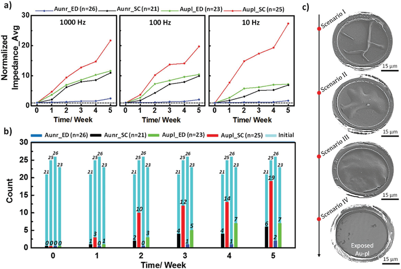
Accelerated aging results for spin-coated (SC) and electrodeposited (ED) PEDOT:PSS microelectrodes with Au-nr and Au-pl substrates. a) Normalized impedance average of different PEDOT:PSS-based microelectrodes; 1) spin-coated on Au-nr (Aunr_SC, black), 2) electrodeposited on Au-nr (Aunr_ED, blue), 3) spin-coated on Au-pl (Aupl_SC, red), and 4) electrodeposited on Au-pl (Aupl_ED, green), at 1000, 100, and 10 Hz frequencies as a function of accelerated aging period in PBS at 60 °C. b) Numbers of “nonfunctional” channels per device type; defined upon exceeding threshold impedance of 100 kΩ by microelectrodes 1 kHz impedance value, as a function of accelerated aging period. Black, red, blue, and green colors correspond to the Aunr_SC, Aupl_SC, Aunr_ED, and Aupl_ED PEDOT:PSS-based microelectrodes, respectively. The light-blue histograms present the total numbers of functional channels per device type at the beginning of the aging experiment. c) Different delamination behaviors of spin-coated PEDOT:PSS film ranging from partial delamination (scenario I or II) to a full delamination (scenario III) and detachment (scenario IV) from the Au-pl substrate.
In different studies, PEDOT:PSS coating has been deployed as an electrode material where the electrodes were chronically implanted for electrophysiological recordings over the course of a month.[19,22] In most cases, the impedance of the electrodes increased significantly after the first week of implant due to either adverse effects of tissue inflammatory response on the electrode or possible degradation of the PEDOT:PSS coating upon implant. In these studies, the quality, morphology, and adhesion/stability of the electrodes have not been reported. For spin-coated PEDOT:PSS electrodes, only two studies have reported the implantation of this type of electrodes with their corresponding stable and long-term action potential recording from the surface of the cortex for an implant period of less than 10 days.[11a,b] The long-term stability of the spin-coated PEDOT:PSS film was not reported. To translate our success in stabilizing PEDOT:PSS in benchtop electrochemical experiments to in vivo, we chronically implanted two sets of PEDOT microelectrodes including spin-cast i) PEDOT:PSS/ Au-nr and ii) PEDOT:PSS/Au-pl onto mouse cerebral cortex for 10 weeks. For implantation, a craniotomy surgery was performed involving removal of the bone overlaying the barrel cortex, while leaving the dura mater intact. The array was placed on top of the dura mater and covered with a glass “window” (Figure 7a). The window served a double purpose; first, it replaced the bone, second, it allowed visualizing the integrity of the brain tissue, including imaging of blood flow using single-and two-photon microscopy (Figure 7b). After the implantation, the mouse was returned to its home cage and allowed to move freely in the cage for 10 weeks. After device explanation, FIB slicing and SEM imaging were performed on the PEDOT arrays to examine the electrode morphology. Figure 7c demonstrates the tilted view SEM image of a explanted PEDOT:PSS/ Au-nr microelectrode, showing overall stable mechanical condition for spin-cast PEDOT film. To examine the PEDOT/metal interface, a FIB cut was performed at the electrode edge. The following cross-sectional SEM image at the FIB cut, shown in Figure 7d, reveals a tight confinement of PEDOT film within the 3D structure of the Au-nr film, preventing polymer film delamination. In contrast, conventional PEDOT:PSS film on Au-pl electrodes experienced significant morphological changes illustrated with either partial or full polymer delamination, as shown in SEM images of Figure 7e,g, respectively. To verify the partial and full PEDOT film delamination on Au-pl electrodes, FIB cuts were performed at the electrodes edge. Cross-sectional SEM image, shown in Figure 7f, demonstrates retained (intact) polymer film on Au-pl substrate, while PEDOT film delaminated at another electrode side, as highlighted in Figure 7e by white dashed line. FIB cut also was performed at an electrode edge shown in Figure 7g which showed absence of PEDOT film as the worst PEDOT stability case. The Au-pl substrate exposure was perceptible upon continuous extension of metal substrate underneath parylene C passivation layer, shown in cross-sectional SEM image of Figure 7h. Indeed, full exposure of Au-pl underlying substrate indicates a PEDOT:PSS film delamination from the Au-pl substrate after the 10 week chronic implant. The surface morphology of all 32 channels per device type are presented in Figure S9 (Supporting Information, PEDOT:PSS/ Au-pl) and Figure S10 (Supporting Information, PEDOT:PSS/ Au-nr). It should be noted that similar morphological changes or delamination of spin-coated PEDOT film from Au-pl substrate (Figures 6c and 7e,g), observed in both in vivo and soaking tests, could correlate their degradation mechanism on polymer film.
Figure 7.

In vivo stability results after 10 weeks chronic implants for spin-coated PEDOT:PSS on Au-nr and Au-pl microelectrodes (D = 50 µm). a) Top view image of the chronically implanted PEDOT array on the mouse brain with a glass coverslip on top. b) Maximum intensity projection of Alexa 680–dextran-labeled blood plasma below the PEDOT:PSS/Au-nr array (individual electrodes outlined with dashed yellow lines). Image shows vasculature up to 300 µm below the cortical surface. Data were acquired with two-photon microscopy 9.5 weeks after implantation. c) Tilted view (50°) SEM image of the explanted PEDOT:PSS/Au-nr microelectrode with sliced FIB cut, highlighted by red box. d) Cross-sectional SEM image at the FIB cut section, showing a fully anchored PEDOT:PSS film within 3D structure of Au-nr film. e) Tilted view (50°) SEM image of the explanted PEDOT:PSS/Au-pl microelectrode (scenario I); sliced FIB cut is highlighted by blue box. Boundary of partially delaminated PEDOT:PSS and underlying Au-pl substrate is signified by white dashed line for ease of illustration. f) Cross-sectional SEM image at the FIB cut section, showing the PEDOT:PSS/Au-pl film interface where PEDOT film is still attached on Au-pl substrate. g) Tilted view (50°) SEM image of the explanted PEDOT:PSS/Au-pl microelectrode (scenario II), showing fully exposed Au-pl underlying substrate as the result of polymer delamination; sliced FIB cut is highlighted by yellow box. Extension of the Au-pl substrate underneath the parylene C passivation layer, shown in h) cross-sectional SEM image at the FIB cut section, indicating fully delamination of the PEDOT:PSS film from Au-pl substrate upon chronic implant.
Finally, to assess potentially aversive biological responses such as tissue inflammation beneath the implanted electrodes, we performed a histological evaluation 10 weeks after implantation. Therefore, hematoxylin and eosin (H&E) staining as well as immunohistochemical staining with antibodies that label neurons neuronal nuclei antigen (NeuN), astrocytes glial fibrillary acidic protein (GFAP), and microglia ionized calcium-binding adapter molecule 1 (IBA1) were performed on brain slices. An overview of the H&E staining is shown in Figure 8a, including an enlarged view of the cortex; location of the implantation site on the left hemisphere as well as the contralateral site (right hemisphere, no implant) for control, are highlighted. Figure 8b shows representative stainings of neurons, astrocytes, and microglia of the (left) cortex underneath the implant and the contralateral (right) side. The staining with NeuN did not reveal any changes in neuronal density beneath the implant. In comparison to the contralateral hemisphere, the antibody staining of GFAP and IBA1 showed a 40–45% or 18–20% increase of astrocyte and microglia densities, respectively. However, astrocyte and microglia densities are known to increase after craniotomy,[23] therefore, they may not indicate a tissue reaction to the implant itself, but to the implantation procedure, in particular the craniotomy.
Figure 8.

Histological analysis of mouse brain from an animal implanted with a PEDOT:PSS/Au-nr microelectrode array. The array was left for 10 weeks after implantation before tissue analysis was performed. a) Image of a tissue section after hematoxylin/eosin (H&E) staining. Top, enlarged image of the cerebral cortex; the barrel cortex below the implant (implanted site, left green box) and the contralateral site (right green box), which serves as control, are highlighted. b) Magnified views of immunohistochemical staining of implanted and contralateral site (as indicated by green boxes in panel (a)) with NeuN antibodies to detect neurons (top), GFAP antibodies to detect astrocytes (middle), and IBA1 antibodies to detect microglia (bottom).
The biological applications of PEDOT:PSS materials are rapidly accelerating for in vitro diagnostics[11a,24] and for in vivo ele ctrophysiology.[1b,c,11a] The adhesion and mechanical stability of PEDOT:PSS electrophysiology devices are imperative for their transition for chronic implants and for neural stimulation. In this study, we introduced the fabrication and integration of the Au-nr film with standard PEDOT:PSS neural probe fabrication on flexible parylene C substrates to improve its adhesion and stability. By providing larger interface area and serving as a mechanical anchor for the PEDOT:PSS layers, a Au-nr adhesion layer improved the stability of the PEDOT:PSS-based electrodes (both spin-coated and electrodeposited PEDOT:PSS devices), under both active CV stressing and passive accelerated aging experiments, contingent on polymer coating thicknesses studied in this work. The Au-nr adhesion layer demonstrated tenfold stability improvement of PEDOT:PSS-based electrodes compared to that of Au-pl substrates under CV stress for both macro- and microscaled electrodes. Furthermore, 92% of electrodeposited PEDOT:PSS electrodes remained electroactively functional after 5 weeks of accelerated aging experiments that is equivalent to ≈6 month chronic implants. The adhesion-promoting effect of Au-nr film was verified under in vivo conditions where the PEDOT film was stabilized within the 3D structure of Au-nr film, but coated polymer on Au-pl electrodes delaminated after a 10 week chronic implant. The adhesion improvement strategy reported here might also benefit other CP neural interface materials for chronic implants or neural stimulation applications where the long-term stability of the CP film is critical.
3. Experimental Section
Device Fabrication—Spin-Coated PEDOT:PSS-Based Electrodes:
The fabrication of the PEDOT:PSS device on Au-pl conductors was similar to previously established protocols and was identical to that of the PEDOT:PSS devices on Au-nr conductors discussed here. Glass slides (Specialty Glass Products Inc.) or Si wafer were used as substrate carriers for deposition of parylene C layers. The glass or Si substrates first were cleaned with acetone/isopropanol (IPA)/deionized (DI) water/ IPA, which was followed by ultrasonic agitation in IPA for 5 min. To facilitate detachment of the device after the process was completed, diluted Micro-90 (0.1%); an antiadhesion layer, was spun-cast at 1500 rpm on the substrate. A first parylene C layer (≈1.9–2.5 µm) was deposited by chemical vapor deposition using a PDS 2010 Parylene coater system. Prior to metallization, metal lead patterns were defined using a Karl Suss MA6 mask aligner using NR9–3000 negative resist and subsequently developed. 15 nm Cr adhesion layer and 100 nm Au contact layer were then deposited using Temescal BJD 1800 electron beam evaporator, and metal leads were defined by a liftoff process in acetone. Then, patterns of the electrode sites were defined using NR9–6000 negative resist and a Karl Suss MA6 mask aligner for exposure. A 15/100 nm Cr/Au layer was sputtered followed by deposition of ≈0.5 µm thick AuAg alloy using a cosputtering technique performed at 400 W radio frequency (RF) and 60 W (DC) power for the codeposition of Ag and Au, respectively. A liftoff process in acetone followed shortly after. To realize Au-nr film on electrode sites, dealloying was performed in nitric acid at 60 °C for 2 min. O2 plasma (Oxford Plasmalab 80 RIE) was then applied for 2 min (150 W RF power) to activate the surface of parylene C for enhancing the adhesion of the subsequent encapsulating parylene C layer. A layer of ≈1.9–2.5 µm parylene C was then deposited and followed by coating another Micro-90 antiadhesion layer; with slightly higher concentrated Micro-90 (1% as opposed to 0.1% for the first layer) to facilitate the separation of the subsequent layers. Then, a third parylene C layer was deposited as sacrificial layer. To define the patterns on electrode sites, a thick 2010 SU-8 photoresist layer was exposed and developed using Karl Suss MA6 mask aligner and SU8 developer. Prior to deposition of PEDOT:PSS film, O2 plasma was used to etch the openings in the third and second parylene C layers. 20 mL aqueous dispersion of PEDOT:PSS (pH 1000 from Clevios) was mixed with ethylene glycol (5 mL), dodecylbenzene sulfonic acid (DBSA, 50 µL), and 1 wt% of (3-glycidyloxypropyl)trimethoxysilane (GOPS), and the solution was spun-cast at 650 rpm for 30 s and prebaked at 95 °C for 1 min. Then, to define the PEDOT:PSS film on top of Au-pl or Au-nr electrode sites, the sacrificial parylene C layer was mechanically peeled off. Finally, the devices were cured at 140 °C for 1 h and then immersed in DI water to remove any Micro-90 residue from the device surface.
Device Fabrication—Electrodeposited PEDOT:PSS-Based Electrodes:
First, Au-pl and Au-nr macro-/microarrays were fabricated following a similar procedure to that of spin-coated PEDOT:PSS devices up to PEDOT:PSS coating step. At the final step, PEDOT:PSS film was electrodeposited rather spun-cast. Prior to the PEDOT:PSS electrodeposition, 20 CV cycles were performed on all channels within −0.6–0.6 V versus Ag/AgCl in PBS as an electrochemical cleaning step. Then PEDOT:PSS was electrodeposited from 0.01 M EDOT in 2.0 g per 100 mL NaPSS aqueous dispersion (both were purchased from Sigma-Aldrich) under potentiostatic conditions at a potential of 0.9 V versus Ag/AgCl in a three electrode setup, i.e., Ag/AgCl electrode as a reference electrode, a large platinum electrode as a counter electrode, and the target microarray/macrodot arrays as the working electrode, at a constant temperature of 27 °C using a GAMRY interface 1000E. Polymerization was driven for 20 s at or below current density of 0.5 mA cm−2, resulting in ≈220 nm thick PEDOT:PSS film deposition on the electrode sites.
Device Characterization:
The SEM images were acquired using an FEI SFEG ultrahigh resolution SEM at 5 kV accelerating voltage. To perform FIB slicing, FEI Scios DualBeam FIB/SEM system was used. GAMRY interface 1000E was used to perform EIS in 0.01 M 1 × PBS) solution, using a three electrode configuration, i.e., PEDOT:PSS electrodes as the working electrode, Ag/AgCl electrode as a reference electrode, a large platinum electrode as a counter electrode. 10 mV root-mean-square (RMS) sinusoidal signal with zero DC bias were applied and the frequency was swept from 1 Hz to 10 kHz. The stress testing was performed in terms of cyclic voltammetry under low current density, near equilibrium conditions in (1×) PBS solution, with the tested electrode potential swept cyclically within the potential windows of −0.6–0.6 V relative to the Ag/AgCl electrode at constant scan rate of 100 mV s−1 with 5 mV potential steps.
Accelerated Aging Experiment:
Devices were stored in PBS at 60 °C with a regular 1 week period to take out from the solution for EIS measurements and optical microscopic inspection using Zeiss Axio fluorescence microscope.
Animal Procedures:
All experimental procedures were performed in accordance with the guidelines established by the University of California San Diego (UCSD) Institutional Animal Care and Use Committee (IACUC). Two adult mice on a C57BL/6 background were used. The procedure for craniotomy over the left barrel cortex and glass window implantation was modified from a previously described procedure.[25] Briefly, dexamethasone was injected before surgery to prevent brain swelling. Mice were anesthetized with Ketamine (100 mg kg−1) and Xylazine (10 mg kg−1), and a single dose of Buprenorphine (0.05 mg kg−1) was applied. A 3 mm diameter craniotomy with the center coordinates of anterior-posterior (A–P) 2 mm and left-right (L–R) 3 mm (relative to bregma) was performed, and an aluminum headpost was mounted over the other (right) hemisphere. After bone removal, the electrode array was placed on the dura mater, and the glass window assembly (made of three 3 mm coverslips and one 5 mm coverslip bonded together with optical adhesive) was fit within the exposure on top of the array. Then, the circumference of the glass window was sealed with dental acrylic. A combination of Sulfatrim and Ibuprofen was given via drinking water from 1 day before until 5 days after surgery.
To visualize the vasculature via two-photon imaging, 100 μL of 5% w/v Alexa Fluor 680–dextran in PBS was injected intravenously. Two-photon images were obtained using an Ultima two-photon laser scanning microscopy system from Bruker Fluorescence Microscopy equipped with an optical parametric oscillator tuned to 1360 nm (Chameleon Compact OPO, Coherent) that was pumped by a Ti:sapphire laser at 790 nm.[26] Alexa Fluor 680 was imaged through a 20× water immersion objective (UMPLFLN20XW, Olympus); fluorescence was detected with a cooled GaAsP detector (Hamamatsu, H7422P-40).
For histology, animals received a Pentobarbital (200 mg kg−1) overdose and were transcardially perfused with heparin–PBS followed by 4% paraformaldehyde in PBS. H&E staining and immunohistochemistry were performed on 5 μm paraffin sections according to standard procedures at the Moores Cancer Center Histology Core at the UCSD.
Statistical Analysis:
To normalize the presented data in Figure 6 (aging results), each representative impedance value for the weeks of 1, 2, 3, 4, and 5 was normalized to its initial value, as measured before initiating the aging experiment using Matlab software. Averaged data (mean) and the corresponding SD were presented in the form of (mean ± SD) and sample size of (n). The fits for the extracted EIS electrochemical components were carried out using custom-made fitting algorithm using Matlab.
Supplementary Material
Acknowledgements
The authors acknowledge financial support for this work from the National Science Foundation under Award No. ECCS-1743694 and from the Center for Brain Activity Mapping at UC San Diego. The authors would like to thank the Nano3 staff at the UC San Diego Qualcomm Institute for supporting the fabrication facilities and Dr. Valeria Estrada and colleagues at the Histology and Immunohistochemistry division of the Moores Cancer Center.
Footnotes
Supporting Information
Supporting Information is available from the Wiley Online Library or from the author.
Conflict of Interest
The authors declare no conflict of interest.
Contributor Information
Mehran Ganji, Integrated Electronics and Biointerfaces Laboratory, Department of Electrical and Computer Engineering, University of California San Diego, La Jolla, CA 92093, USA.
Lorraine Hossain, Materials Science and Engineering Program University of California San Diego La Jolla, CA 92093, USA.
Atsunori Tanaka, Materials Science and Engineering Program University of California San Diego La Jolla, CA 92093, USA.
Martin Thunemann, Department of Radiology, University of California San Diego, La Jolla, CA 92093, USA.
Eric Halgren, Department of Neurosciences and Radiology, University of California San Diego, La Jolla, CA 92093, USA.
Vikash Gilja, Integrated Electronics and Biointerfaces Laboratory, Department of Electrical and Computer Engineering, University of California San Diego, La Jolla, CA 92093, USA.
Anna Devor, Department of Neurosciences and Radiology, University of California San Diego, La Jolla, CA 92093, USA.
Shadi A. Dayeh, Integrated Electronics and Biointerfaces Laboratory, Department of Electrical and Computer Engineering, University of California San Diego, La Jolla, CA 92093, USA, Materials Science and Engineering Program University of California San Diego La Jolla, CA 92093, USA
References
- [1] a).Green R, Abidian MR, Adv. Mater 2015, 27, 7620; [DOI] [PMC free article] [PubMed] [Google Scholar]; b) Ganji M, Kaestner E, Hermiz J, Rogers N, Tanaka A, Cleary D, Lee SH, Snider J, Halgren M, Cosgrove GR, Carter BS, Barba D, Uguz I, Malliaras GG, Cash SS, Gilja V, Halgren E, Dayeh SA, Adv. Funct. Mater 2018, 28, 1700232; [Google Scholar]; c) Rivnay J, Inal S, Salleo A, Owens RM, Berggren M, Malliaras GG, Nat. Rev. Mater 2018, 3, 17086; [Google Scholar]; d) Cogan SF, Annu. Rev. Biomed. Eng 2008, 10, 275; [DOI] [PubMed] [Google Scholar]; e) Cui X, Martin DC, Sens. Actuators, B 2003, 89, 92. [Google Scholar]
- [2] a).Ganji M, Dayeh S, presented at ECS Meeting Abstracts, Washington, DC, USA, October 2017; [Google Scholar]; b) Ganji M, Tanaka A, Gilja V, Halgren E, Dayeh SA, Adv. Funct. Mater 2017, 10.1002/adfm.201703019. [DOI] [PMC free article] [PubMed] [Google Scholar]
- [3] a).Im SG, Yoo PJ, Hammond PT, Gleason KK, Adv. Mater 2007, 19, 2863; [Google Scholar]; b) Cui XT, Zhou DD, IEEE Trans. Neural Syst. Rehabil. Eng 2007, 15, 502; [DOI] [PubMed] [Google Scholar]; c) Gerwig R, Fuchsberger K, Schroeppel B, Link GS, Heusel G, Kraushaar U, Schuhmann W, Stett A, Stelzle M, Front. Neuroeng 2012, 5, 8; [DOI] [PMC free article] [PubMed] [Google Scholar]; d) Thaning EM, Asplund ML, Nyberg TA, Inganäs OW, von Holst H, J. Biomed. Mater. Res., Part B 2010, 93B, 407; [DOI] [PubMed] [Google Scholar]; e) Ham DJ, Lee JS, Energies 2009, 2, 873. [Google Scholar]
- [4].Chen X, Xing K-Z, Inganäs O, Chem. Mater 1996, 8, 2439. [Google Scholar]
- [5] a).Cho C-K, Hwang W-J, Eun K, Choa S-H, Na S-I, Kim H-K, Sol. Energy Mater. Sol. Cells 2011, 95, 3269; [Google Scholar]; b) Green RA, Hassarati RT, Bouchinet L, Lee CS, Cheong GL, Jin FY, Dodds CW, Suaning GJ, Poole-Warren LA, Lovell NH, Biomaterials 2012, 33, 5875; [DOI] [PubMed] [Google Scholar]; c) Green RA, Lovell NH, Wallace GG, Poole-Warren LA, Biomaterials 2008, 29, 3393. [DOI] [PubMed] [Google Scholar]
- [6].Luo X, Weaver CL, Zhou DD, Greenberg R, Cui XT, Biomaterials 2011, 32, 5551. [DOI] [PMC free article] [PubMed] [Google Scholar]
- [7].Wei B, Liu J, Ouyang L, Kuo C-C, Martin DC, ACS Appl. Mater. Interfaces 2015, 7, 15388. [DOI] [PubMed] [Google Scholar]
- [8].Ouyang L, Wei B, Kuo C.-c., Pathak S, Farrell B, Martin DC, Sci. Adv 2017, 3, e1600448. [DOI] [PMC free article] [PubMed] [Google Scholar]
- [9].Cui X, Martin DC, Sens. Actuators, A 2003, 103, 384. [Google Scholar]
- [10].Boehler C, Oberueber F, Schlabach S, Stieglitz T, Asplund M, ACS Appl. Mater. Interfaces 2017, 9, 189. [DOI] [PubMed] [Google Scholar]
- [11] a).Khodagholy D, Gelinas JN, Thesen T, Doyle W, Devinsky O, Malliaras GG, Buzsáki G, Nat. Neurosci 2015, 18, 310; [DOI] [PMC free article] [PubMed] [Google Scholar]; b) Khodagholy D, Gelinas JN, Buzsáki G, Science 2017, 358, 369; [DOI] [PMC free article] [PubMed] [Google Scholar]; c) Hermiz J, Rogers N, Kaestner E, Ganji M, Cleary D, Snider J, Barba D, Dayeh S, Halgren E, Gilja V, presented at The 38th Annual Int. Conf. of the IEEE Engineering in Medicine and Biology Society (EMBC), Orlando, FL, August 2016. [DOI] [PubMed] [Google Scholar]
- [12] a).Erlebacher J, Aziz MJ, Karma A, Dimitrov N, Sieradzki K, Nature 2001, 410, 450; [DOI] [PubMed] [Google Scholar]; b) Seker E, Berdichevsky Y, Begley MR, Reed ML, Staley KJ, Yarmush ML, Nanotechnology 2010, 21, 125504. [DOI] [PMC free article] [PubMed] [Google Scholar]
- [13] a).Scheirs J, Compositional and Failure Analysis of Polymers: A Practical Approach, John Wiley & Sons, Hoboken, NJ: 2000; [Google Scholar]; b) Otero T, Boyano I, J. Phys. Chem. B 2003, 107, 6730; [Google Scholar]; c) Heinze J, Frontana-Uribe BA, Ludwigs S, Chem. Rev 2010, 110, 4724. [DOI] [PubMed] [Google Scholar]
- [14].Uguz I, Ganji M, Hama A, Tanaka A, Inal S, Youssef A, Owens RM, Quilichini PP, Ghestem A, Bernard C, Adv. Health- care Mater 2016, 5, 3094. [DOI] [PubMed] [Google Scholar]
- [15].Ganji M, Elthakeb AT, Tanaka A, Gilja V, Halgren E, Dayeh SA, Adv. Funct. Mater 2017, 10.1002/adfm.201703018. [DOI] [Google Scholar]
- [16] a).Giovannitti A, Thorley KJ, Nielsen CB, Li J, Donahue MJ, Malliaras GG, Rivnay J, McCulloch I, Adv. Funct. Mater 2018, 28, 1706325; [Google Scholar]; b) Park B.-w., Yang L, Johansson EM, Vlachopoulos N, Chams A, Perruchot C, Jouini M, Boschloo G, Hagfeldt A, J. Phys. Chem. C 2013, 117, 22484. [Google Scholar]
- [17].Cherevko S, Topalov AA, Zeradjanin AR, Katsounaros I, Mayrhofer KJ, RSC Adv 2013, 3, 16516. [Google Scholar]
- [18].Hermiz J, Rogers N, Kaestner E, Ganji M, Cleary DR, Carter B, Barba D, Dayeh S, Halgren E, Gilja V, NeuroImage 2018, 176, 454. [DOI] [PubMed] [Google Scholar]
- [19].Venkatraman S, Hendricks J, King ZA, Sereno AJ, Richardson-Burns S, Martin D, Carmena JM, IEEE Trans. Neural Syst. Rehabil. Eng 2011, 19, 307. [DOI] [PubMed] [Google Scholar]
- [20] a).Malliaras G, Abidian MR, Adv. Mater 2015, 27, 7492; [DOI] [PMC free article] [PubMed] [Google Scholar]; b) Buzsáki G, Nat. Neurosci 2004, 7, 446. [DOI] [PubMed] [Google Scholar]
- [21].Rubehn B, Stieglitz T, Biomaterials 2010, 31, 3449. [DOI] [PubMed] [Google Scholar]
- [22] a).Kozai TD, Catt K, Du Z, Na K, Srivannavit O, Haque R-U, Seymour J, Wise KD, Yoon E, Cui XT, IEEE Trans. Biomed. Eng 2016, 63, 111; [DOI] [PMC free article] [PubMed] [Google Scholar]; b) Kozai TDY, Langhals NB, Patel PR, Deng X, Zhang H, Smith KL, Lahann J, Kotov NA, Kipke DR, Nat. Mater 2012, 11, 1065; [DOI] [PMC free article] [PubMed] [Google Scholar]; c) Ludwig KA, Uram JD, Yang J, Martin DC, Kipke DR, J. Neural Eng 2006, 3, 59; [DOI] [PubMed] [Google Scholar]; d) Patel PR, Zhang H, Robbins MT, Nofar JB, Marshall SP, Kobylarek MJ, Kozai TD, Kotov NA, Chestek CA, J. Neural Eng 2016, 13, 066002; [DOI] [PMC free article] [PubMed] [Google Scholar]; e) Ludwig KA, Langhals NB, Joseph MD, Richardson-Burns SM, Hendricks JL, Kipke DR, J. Neural Eng 2011, 8, 014001; [DOI] [PMC free article] [PubMed] [Google Scholar]; f) Schander A, Stemmann H, Tolstosheeva E, Roese R, Biefeld V, Kempen L, Kreiter A, Lang W, Sens. Actuators, A 2016, 247, 125. [Google Scholar]
- [23] a).Drew PJ, Shih AY, Driscoll JD, Knutsen PM, Blinder P, Davalos D, Akassoglou K, Tsai PS, Kleinfeld D, Nat. Methods 2010, 7, 981; [DOI] [PMC free article] [PubMed] [Google Scholar]; b) Dorand RD, Barkauskas DS, Evans TA, Petrosiute A, Huang AY, IntraVital 2014, 3, e29728; [DOI] [PMC free article] [PubMed] [Google Scholar]; c) Guo D, Zou J, Rensing N, Wong M, PLoS One 2017, 12, e0170005. [DOI] [PMC free article] [PubMed] [Google Scholar]
- [24] a).Pires F, Ferreira Q, Rodrigues CA, Morgado J, Ferreira FC, Biochim. Biophys. Acta, Gen. Subj 2015, 1850, 1158; [DOI] [PubMed] [Google Scholar]; b) Sessolo M, Khodagholy D, Rivnay J, Maddalena F, Gleyzes M, Steidl E, Buisson B, Malliaras GG, Adv. Mater 2013, 25, 2135; [DOI] [PubMed] [Google Scholar]; c) Pas J, Pitsalidis C, Koutsouras DA, Quilichini PP, Santoro F, Cui B, Gallais L, O’Connor RP, Malliaras GG, Owens RM, Adv. Biosyst 2018, 2, 1700164. [Google Scholar]
- [25].Goldey GJ, Roumis DK, Glickfeld LL, Kerlin AM, Reid RC, Bonin V, Schafer DP, Andermann ML, Nat. Protoc 2014, 9, 2515. [DOI] [PMC free article] [PubMed] [Google Scholar]
- [26].Kobat D, Durst ME, Nishimura N, Wong AW, Schaffer CB, Xu C, Opt. Express 2009, 17, 13354. [DOI] [PubMed] [Google Scholar]
Associated Data
This section collects any data citations, data availability statements, or supplementary materials included in this article.