Abstract
A novel series of lead zirconate titanate (PZT) ceramic–polymer composites has been developed and characterized. The matrix polymer is a liquid crystalline thermosetting resin (LCR) based on a HBA-HNA backbone and phenylethynyl end-groups. The composites show excellent high temperature processability. The dielectric properties were studied as a function of PZT volume fraction and processing conditions. Piezoelectric behaviour was compared to Yamada et al. model for 0–3 composites. For a moderate PZT volume fraction a high value for the piezoelectric stress constant of g 33 = 48 mV m/N was measured, which, in combination with a good chemical and thermal resistance of the polymer matrix, makes the material a good candidate for sensor applications at elevated temperatures. The liquid crystalline thermosetting character of the polymer imparts interesting high temperature post-formability.
Keywords: Dielectric Constant, Piezoelectric Property, Poling Direction, Piezoelectric Behaviour, Rhombohedral Crystal Structure
Introduction
Lead zirconate titanate (PZT) ceramics exhibit ideal sensor and actuator characteristics. However, being ceramics, they are brittle and hard to process [1]. Hence several attempts have been made to develop PZT polymer composites which combine much easier processing with a sufficient sensitivity and some ductility. Various PZT–polymer combinations have been explored including mostly PZT-PVDF systems [2–8] and PZT-epoxy systems [9, 10] with moderate success. A major problem in developing composites with adequate properties is the substantial decrease in piezoelectric sensitivity of these systems which leads to a high minimal PZT volume fraction in order to achieve sufficient sensing or actuating characteristics. This high PZT content often leads to poor material homogeneity which in turn lowers the mechanical properties. Furthermore, the polymers used are either of a truly thermosetting nature (e.g. epoxies), making post-forming of the composites impossible, or lack adequate thermal and chemical stability (PVDF). Such a post-formability characteristic would enable the production of single and double curved sensors from simple flat precursor sheet material and would be very attractive for new manufacturing routes for complex sensors, for instance as integrated sensors in fibre reinforced composite structures.
Recently a potentially attractive class of polymers to be used as matrix polymers for high performance PZT–polymer matrices has been developed: liquid crystalline thermosetting resins (LCR) [11]. These thermoset polymers are obtained by thermal curing of thermotropic liquid crystalline oligomer systems, in which thermally reactive end groups terminate the oligomers. Before curing the oligomeric resin has a low melt viscosity and behaves as a thermoplastic resin. When the resin is heated to over 300 °C the reactive end groups will react and form a network. The extent of the curing reaction can be controlled by the temperature and length of the curing step. Due to the nature of the polymer backbone and its liquid crystalline nature the LCR has excellent high temperature properties and excellent chemical resistance. The low viscosity and its good bonding characteristics yield an excellent processability and adhesion to the PZT particles [12].
In this paper we report the first set of experiments on such PZT-LCR composites. The piezoelectric properties obtained as a function of PZT volume and polymer properties are compared to theoretically predicted values for 0–3 topology composites (i.e. non-aligned, isolated particles in a continuum matrix [2, 13]). The composites show the potential to replace existing piezoelectric materials, especially in harsh environments, such as, automotive or aerospace applications.
Theory for the piezoelectric behaviour of 0–3 composites
The piezoelectric properties of PZT–polymer composites are a function of the volume fraction  of the PZT particulate inclusions, the connectivity of the PZT particles in three dimensions and the piezoelectric properties of the particles. The most appropriate model to describe the dielectric properties of the LCR-PZT composites to be analyzed in this work is the model by Yamada et al. [2] for composites with 0–3 connectivity (i.e. non-aligned, isolated particles in a continuum matrix). The following equations describe the principal piezoelectric parameters relevant for this work and their dependence on microstructural parameters.
The piezoelectric voltage constant (g 33) is defined as the ratio of the piezoelectric charge constant (d 33) over the dielectric constant of the composite material (ɛ33):
 |
1 |
The piezoelectric charge constant of the composite in the poling direction, d 33, is given by
 |
2 |
where α is the poling ratio of the ceramic inclusions, E
2 is the local electric field coefficient acting on the ceramic inclusions and  is piezoelectric charge constant for the ceramic inclusions.
The local electric field in the poling direction acting on the particles, E 2, depends on the ratio of the dielectric constants of the particles and the matrix as follows:
 |
3 |
Finally, the dielectric constant of the composite in the poling direction, ɛ33, is given by
 |
4 |
where  is the dielectric constant of the polymer matrix in the poling direction,
  is the dielectric constant of the ceramic inclusions in the poling direction and n is a dimensionless parameter depending on the shape and orientation of the ceramic particles.
By substituting Eqs. 2–4 into relation (1) the following relation for the piezoelectric voltage constant, g 33, of the composite material is found.
 |
5 |
By fitting experimental data for ɛ33 and d 33 values of composites and varying the structural parameter n, d 33 and g 33 values for volume fractions up to the theoretical maximum can be predicted. The model was shown to predict the piezoelectric charge constants (d 33) of PZT-PVDF composites with PZT volume fractions up to 0.7 rather well [2].
Experimental
LCR polymer
The liquid crystalline resin (LCR) used here is composed of 6-hydroxy-2-naphthoic acid (HNA) and 4-hydroxybenzoic acid (HBA) precursors (Fig. 1), forming a resin of oligomers of a well defined molecular weight terminated with reactive phenylethynyl end-groups. The synthesis of these polymer systems is described in detail elsewhere [11, 12].
Fig. 1.
The molecular structure of an LCR oligomer with an HBA/HNA ratio of x/y and n backbone repeat units
When selecting the molecular weight and backbone composition most appropriate for this work, a low melt viscosity was considered as being the main criterion to yield adequate processability as the polymer seems to have intrinsically good wettability. Earlier work [11] has shown that for a given molecular weight LCR polymers with a 50/50 HBA/HNA backbone ratio exhibit the lowest melt viscosity. Thus, for the preparation of the composite material a polymer with a backbone composition of 50/50 mol% HBA/HNA ratio and a molecular weight of 5,000 g/mol was selected. This polymer will be referred to as 50-LCR-5k in the remainder of this work. The polymer was synthesized and ground to powder with particles typically being less than 0.5 mm in diameter. A molecular weight of 5,000 g/mol was selected as this combines a low enough viscosity, good final mechanical properties and a sufficient number of reactive end groups to form both a strong network and an excellent adhesion to the PZT particles.
In addition, an LCR variant with a higher molecular weight and different backbone structure was selected, in order to have an indication of the effect of matrix variation on composite properties. A 9,000 g/mol polymer with an HBA/HNA ratio of 73/27 was used for this purpose (73-LCR-9k).
PZT powder
The PZT powder used in this research is a pre-sintering powder for PZT5-A4 grade PZT, a ‘soft’ PZT with 1 mol% Nb added as a dopant. The powder was used both in the as received and the calcinated state. The as received PZT-powder is a pre-sintering PZT powder. X-ray diffraction studies revealed that in this powder the calcining reaction, needed to obtain a Perovskite phase, was not fully completed. The XRD spectrum revealed the presence of multiple phases, indicating locally fluctuating solute concentrations of PbZrO3 and PbTiO3. In this work this powder is referred to as PZT. The base powder was further annealed in order to complete the calcining reaction and establish a 100% Perovskite PZT phase and improve the dielectric properties of the PZT powder. The calcination process was performed as follows. An amount of 213 g of as received PZT powder was put in an Al2O3 crucible, covered with ZrO2 plates and placed in a Lint-Elektronik HT-1880 high temperature sintering oven, and annealed for one hour at 1,000 °C. The agglomerated powder was left to cool to room temperature and de-agglomerated by wet milling in cyclohexane for 12 min in a planetary ball mill. The calcinated PZT powder was dried in a vacuum oven at 120 °C for 16 h to remove all remaining cyclohexane and moisture acquired during storage and transport. In this work the post-annealed PZT powder is referred to as PZTc. The particle size distribution of both powders was measured by laser diffraction analysis on a Beckman Coultier LS 230 particle analyzer operating at a laser wavelength of 750 nm. The particle size distribution parameters are listed in Table 1.
Table 1.
Typical particle size distribution parameters of as received and calcinated PZT powder
| Powder type | d10 (μm) | d50 (μm) | d90 (μm) |
|---|---|---|---|
| as received PZT (PZT) | 0.132 | 1.33 | 3.65 |
| Calcinated PZT (PZTc) | 0.265 | 2.18 | 4.84 |
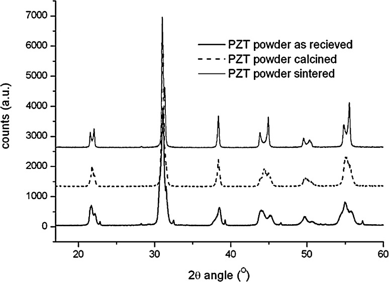
The crystal structural changes due to the calcination process are revealed by X-ray Diffraction (XRD) and are shown in Fig. 2. All diffraction measurements were performed on a Brucker-AXS D5005 diffractometer equipped with an incident beam monochromator and a position sensitive counter. Analysis was conducted using a CuKα1 X-rays (λ = 0.1540562 nm) operated at 40 keV.
Fig. 2.
X-ray diffraction data of as received PZT powder, calcinated PZT powder and sintered PZT5-A4
The as received powder shows the existence of multiple phases, both with tetragonal and rhombohedral crystal structures. The peaks belonging to rhombohedral crystal structures (i.e. phases with high PbZrO3 content) seem to be predominant. A small amount of pure PbTiO3 (e.g. at 2θ angles of 22.2, 31 and 38.5°) is also present in this powder as well as very small non-Perovskite phase (at a 2θ angle of 28.2°). These observations are all indications that the calcining reaction has not been completed, which is typical for pre-sintering ceramic powder.
The calcination of the PZT powder significantly changed the phase distribution in the material. The rombohedral phase is still clearly present, but the pure PbTiO3 fraction seems to have dissolved and the composition seems to have homogenised further. Figure 2 also contains the diffractogram of the material in its optimally sintered structure, taken from a sample of sintered PZT5-A4, which was ground to a powder. In contrast to the as received and calcinated material the PZT powder in its optimally sintered state has a largely tetragonal crystal structure. This tetragonal phase can only form properly if the PbZrO3 and PbTiO3 phases are fully dissolved. It is a well known fact that the magnitude of the piezoelectric effect in PZT is extremely composition dependent. A 48 mol% (tetragonal) or 54 mol% (rhombohedral) solid solution of PbZrO3 in PbTiO3 exhibit only approximately half of the piezoelectric activity of a 52 mol% PbZrO3 in PbTiO3 solution near the MPB [14]. Hence, although the calcining step certainly raised the piezoelectric properties, further improvement is still possible. However, as the aim of the work was to demonstrate the potential of the PZT-LCR composites, the calcinated PZT powder still served its purpose.
PZT-LCR composites manufacturing
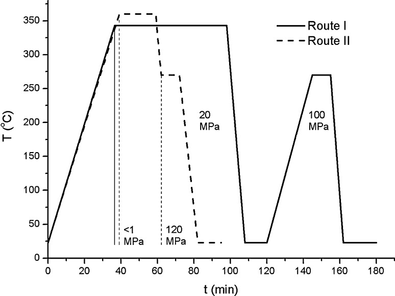
To synthesize these composites, appropriate amounts of PZT powder and LCR powder were weighed using a laboratory balance (Deltarange AG204). These powder mixtures were subsequently mixed in air at 15 °C above melting temperature of the resin in an open 20 cm3 batch mixer powered by a Brabender Plasticorder (model PLE 651) for 5 min, left to cool to room temperature and removed from the mixer. The mixing speed was set at 20 rpm. The composite mixtures were ground to fine powders for further processing. Subsequently, two consolidation routes, route I and route II, were explored, which are shown in Fig. 3. Consolidation route I was derived from earlier measurements on pure LCR resins [11], such that some degree of cross linking was induced in the resin but the degree is such that the polymer maintains a large part of its initial thermoplastic character. Initial pressing attempts resulted in porous films. Therefore, a second high temperature high pressure step was employed to densify the composites. At a temperature of 270 °C the polymer matrix was found to be soft enough to densify under pressure. In consolidation route II, a more technologically relevant pressing cycle was used and the composite powders were dried for 16 h in vacuum at 120 °C before pressing. The composite resin was heated to a higher temperature for a shorter time, leading to a similar degree of cross-linking. Finally, the partly cured composite was subjected to a higher pressure in the densification step. Finally, the cured films, with a typical thicknesses of 200 μm, were cut to shape using a modelling knife, and the edges were smoothened by grinding.
Fig. 3.
Temperature versus time plot for composite consolidation routes I and II. The applied pressure during the pressing cycle is noted between the drop lines for each route
In total six composite variants were produced, with compositions and processing conditions as specified in Table 2.
Table 2.
Definition of composite labels, identifying their constituent volume fractions and consolidation routes
| Composite | LCR type | LCR volume fraction | PZT type | PZT volume fraction | Consolidation route |
|---|---|---|---|---|---|
| 50-LCR-5k/0.10PZT | 50-LCR-5k | 0.9 | ‘as received’ | 0.1 | I |
| 50-LCR-5k/0.25PZT | 50-LCR-5k | 0.75 | ‘as received’ | 0.25 | I |
| 50-LCR-5k/0.40PZT | 50-LCR-5k | 0.6 | ‘as received’ | 0.4 | I |
| 50-LCR-5k/0.55PZT | 50-LCR-5k | 0.45 | ‘as received’ | 0.55 | I |
| 50-LCR-5k/0.40PZTc | 50-LCR-5k | 0.6 | ‘dried and calcined’ | 0.4 | II |
| 73-LCR-9k/0.40PZTc | 73-LCR-9k | 0.6 | ‘dried and calcined’ | 0.4 | II |
The final processing step involves electroding and poling the composite material. Square composite samples (of 5–10 mm side lengths) were electroded by sputtering gold on both sides, leaving a 1 mm border uncovered to inhibit sparking during the poling process. Poling was performed in air at 200 °C by placing the sample on a hot plate and applying the appropriate dc poling voltage for the designated amount of time using a dc high voltage supply (Bertan systems model 205DB-20H). After poling the electric field was removed, the composite was removed from the hot plate and cooled in air to room temperature. Typical poling time was set at 30 min to ascertain maximal poling. No attempts were made to minimise this poling time.
Characterisation techniques
Dielectric characterization
Dielectric spectroscopy was performed using a Novocontrol alpha analyser broadband dielectric spectrometer. Samples were tested in a nitrogen atmosphere in a temperature range of −140 to 250 °C. Composite dielectric constant (ɛ′) and loss factor (ɛ′′) was measured over a frequency range of 0.01 Hz to 3.5 MHz.
Dielectric characterization
The piezoelectric charge constant d 33 was measured at room temperature at a fixed frequency of 110 Hz. Measurements were performed on a piezoelectric d 33 meter (KCF Technologies, model PM3001). The d 33 constant was measured for each sample directly after poling.
Mechanical characterisation
Tensile tests were conducted in a Zwick Roell 20 kN tensile bench fitted with a 1 kN load cell. Six tensile testing samples of each composite (40 mm effective length) were tested, at a crosshead speed of 1 mm/min. The test bench was fitted with rubber grips to ensure uniform stress transfer from the grips to the samples in order to decrease the chance of sample failure at the grips. Both sides of the tensile test sample clamping areas were coated with a 0.5 mm layer of rigid epoxy for the same reason. Therefore, only maximum tensile stress was evaluated, as sample stiffness and elongation at break were not measurable using this test method. Reference samples of pure 50-LCR-5k and 73-LCR-9k polymer were also tested in the same manner.
Dynamic mechanical thermal analysis was performed using a Perkin Elmer Pyris DMTA in a nitrogen atmosphere. A reference sample of pure 50-LCR-5k polymer was also tested. The measurements were performed at 0.1, 1 and 10 Hz, over a temperature range of −100 to 300 °C.
Results and discussion
Composite morphology
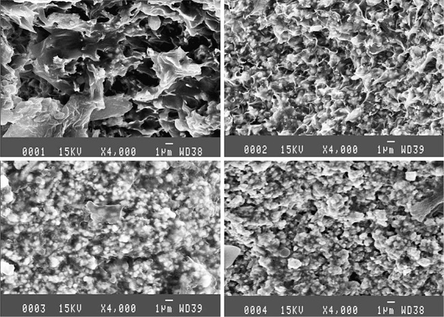
Using the production procedures illustrated in Fig. 3a, b fully dense composites were obtained. A spatially uniform distribution of the PZT particles has been obtained as shown in the SEM micrograph of a fracture surface (Fig. 4). Observations at higher magnification revealed a very good adhesion between the matrix and the PZT particles. Such a good adhesion is typical for the reactive end-group LCR polymer [12].
Fig. 4.
SEM images of fractured composite samples with  (image 0001),
  (image 0002),
  (image 0003) and
  (image 0004). Original images were taken at 4,000 × magnification
Dielectric and piezoelectric properties of the composite material
Dielectric properties of the composite material
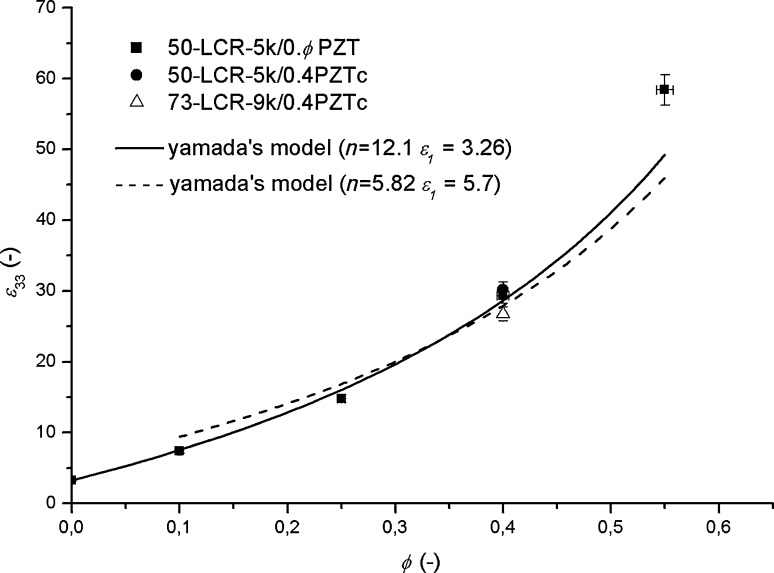
The dielectric constant as a function of the PZT loading fraction is shown in Fig. 5. In this figure the dependence as predicted by the Yamada model is also plotted. The fit equation was determined for composite samples with as received PZT powder only. A relatively good fit was obtained.
Fig. 5.
The dielectric constant (ɛ33) of the composite materials as a function of the PZT volume fraction ( ). Yamada’s model has been fitted to the 50-LCR-5k/0.
  PZT experimental data
The values for the dielectric constants of the pure 50-LCR-5k polymer and the 73-LCR-9k polymer were measured to be 3.26 and 3.64 at room temperature and 110 Hz. The ɛ33 value of (poled) PZT material either in the as received or in the calcinated state was estimated to be equal to that of sintered PZT of ɛr = 1,820. Although the XRD analysis revealed the presence of multiple phases on both sides of the MPB the dependence of the dielectric constant on composition is fairly linear near the overall composition [15] and hence the average value remains the same even while sintering leads to a reduction of the local composition fluctuations.
The best fit of the model predictions to experimental data was obtained for n is 12.1, which corresponds to a 0–3 system with particles with an aspect ratio of approximately 3.5 orientated parallel to the poling direction. This aspect ratio is somewhat higher than the results from SEM analysis, which suggest aspect ratios of 1.5–2. Furthermore, the backscattered electron imaging did not reveal a clear alignment of the particles. A possible explanation for the discrepancy could be the excellent bonding between the PZT particles and the matrix [2]. Local alignment of the polymer chains, which are in a liquid crystalline state prior to curing, along the PZT particle–matrix interface will alter the dielectric constant of this region, (locally) leading to a higher dielectric constant of the matrix material. This alignment effect can be rather strong as the relatively mobile oligomers can be easily oriented. The increase in dielectric constant with filling fraction seems to be slightly greater in composites with as received powder than in composites with calcinated powder. Taking the effective value of the dielectric constant of the polymer as result of local orientation as ɛ = 5.7 instead of ɛ = 3.26 , leads to an n value of n = 5.81, which is consistent with the observed microstructure for composites with PZT volume fractions up to 0.4 and an ellipsoidicity of the particles of 2:1:1, aligned parallel to the poling direction. Another interpretation of the high n value found is that the PZT particles with locally aligned polymer molecules in their vicinity can be treated as high aspect ratio composite aggregates. The high ɛ33 value measured for the 50-LCR-5k/0.55PZT composite, with a PZT volume fraction of 0.55, is attributed to percolation of the PZT particles, as the percolation threshold for spherical particles in a perfectly homogeneous mixture is only 0.6. From Fig. 5 it can also be concluded that the influence of the PZT modification was relatively modest for the variants explored. This is consistent with the above discussion that the influence of calcining PZT powder on the dielectric constant of the powder is small. The effect of the polymer dielectric constant on the composite dielectric constant is also modest, as the dielectric constant of the 73-LCR-9k polymer is only slightly higher than that of the base 50-LCR-5k polymer.
Piezoelectric properties of the composite material
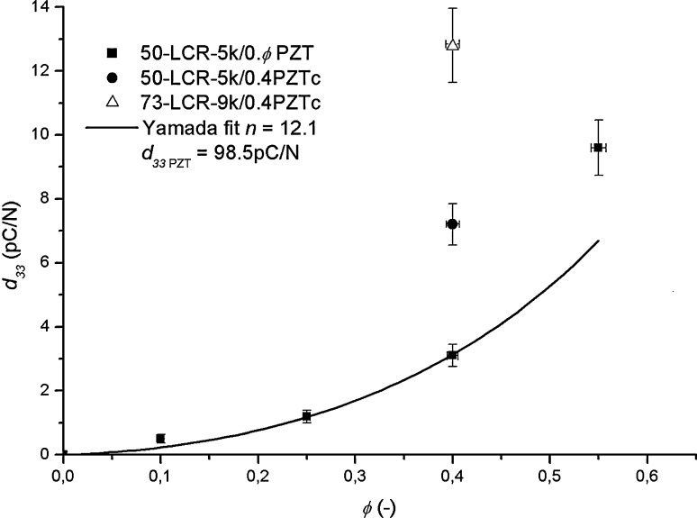
The piezoelectric charge constants (d 33) as a function of the PZT loading fraction are depicted in Fig. 6. The solid line is the predicted dependence for the composites produced with the ‘as received’ PZT powder, using the n value of 12.1 derived from the dielectric constant data. A good agreement is obtained when taking the d 33 value for the as received PZT powder at 98.5 pC/N, which is a realistic value given the variation crystal in the material revealed by the XRD spectrum. These variations in crystal structure as a result of variations in zirconate and titante concentrations in the material correlates with the data found in [14]. The figure also shows that the d 33 value of the samples with the calcinated PZT (PZTc) powder are higher than that for the as received powder. Fitting the Yamada equation to this single data point leads to an estimated value for the d 33 value of the calcinated PZT powder of 200.6pC/N, which is, in accordance with Fig. 2, still below that of optimally sintered PZT5-A4, 480 pC/N.
Fig. 6.
The piezoelectric charge constant (d
33) of the composite materials as a function of the PZT volume fraction ( ). Yamada’s model has been fitted to the 50-LCR-5k/0.
 PZT experimental data
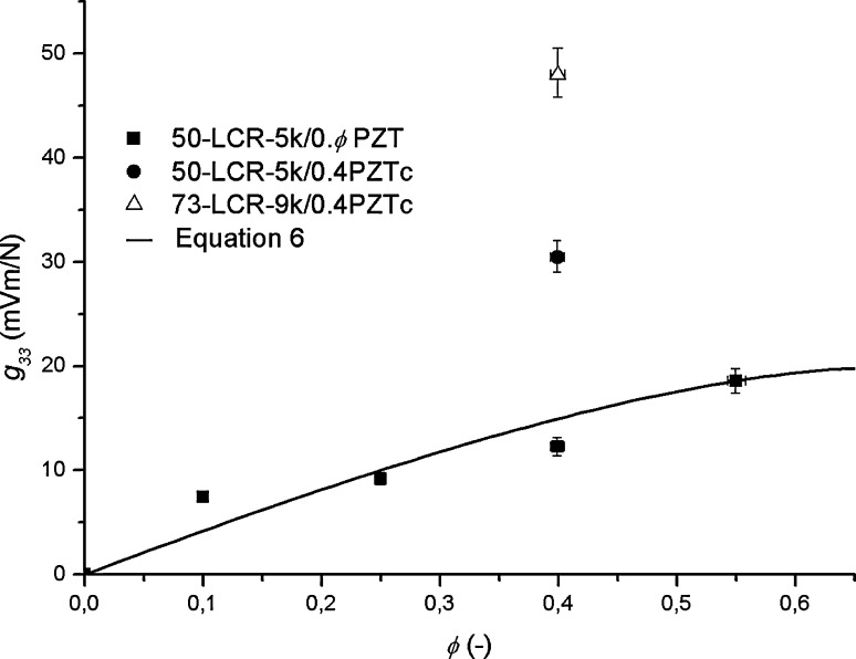
The piezoelectric voltage constant g 33 as a function of the PZT loading fraction is shown in Fig. 7.
Fig. 7.
The piezoelectric voltage constant (g
33) of the composite materials as a function of the PZT volume fraction ( ). Yamada’s model has been fitted to the 50-LCR-5 k/0.
 PZT experimental data
The g 33 values obtained range from 10 mV m/N to 48 mV m/N depending on the volume fraction and properties of the matrix and particulate phase. The highest value obtained of 48 mV m/N for the 73-LCR-9k/0.4PZTc composite compares very favourably to the values reported in the literature for PZT ceramics and PZT–polymer composites (see Table 3). The high g 33 value makes the composite a very attractive material for a sensitive pressure transducer. The PZT-epoxy composite reported in [10] has a similarly high value for g 33 but at a much higher PZT volume fraction and a ternary phase of 1% (volume) carbon black mixed in with the polymer matrix. The high PZT volume fraction leads to a more brittle material and the carbon black leads to an increased dielectric loss rendering the material less suitable for most sensor applications than the PZT_LCR composite presented here.
Table 3.
Dielectric and piezoelectric properties of various types of PZT/polymer composites in comparison to the 73-LCR-9k/0.4PZT composite synthesized in this study
| Type | ɛ33 (poled) | d 33 (pC/N) | g 33 (mV m/N) |
|---|---|---|---|
| 73-LCR-9k / 0.4 PZT | 30 | 13 | 48 |
| PVDF / 0.7 PZT [9] | 100 | 26 | 30 |
| Epoxy/0.685 PZT [11]* | 120 | 50 | 47 |
| PVDF/0.67 PZT [2] | 152 | 48 | 36 |
| PVDF / 0.5 PZT [7] | 95 | 14 | 16 |
| PVDF / 0.5 PZT [7] | 30 | 9 | 36 |
The composite marked with an * has 1.5% carbon black added to the PZT-epoxy mixture
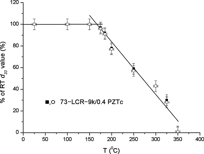
The effects of exposure to a high temperature on the piezoelectric properties of the composite are shown in Fig. 8, which shows the normalized d 33 value at room temperature after exposure of 10 min to an elevated temperature. The figure shows that up to 170 °C the piezoelectric properties are maintained. The degradation at higher temperatures is due to the depolarization in the PZT material itself. The relatively gradual drop in d 33 with temperature is due to the presence of various phases in the PZT powder, each having a slightly different Curie temperature [15]. The LCR polymer used is stable, even for long periods of time, up to temperatures of 300 °C, making the temperature dependence of the composite a function of the intrinsic temperature dependence of the PZT crystal itself.
Fig. 8.
The deterioration of d 33 with temperature. The samples tested were subjected to elevated temperatures and held at this temperature for 10 min. They were subsequently left to cool and measured at room temperature
Mechanical and thermo-mechanical properties
The tensile strength values for the various composites and the pure polymer are listed in Table 4.
Table 4.
Tensile properties of PZT-LCR composites in MPa. Results from a reference measurement of 50-LCR5k polymer are shown for comparison
| Composite type | σt (MPa) |
|---|---|
| 50-LCR-5k/0.1PZT | 26.6 ± 5.3 |
| 50-LCR-5k/0.25PZT | 33.2 ± 4.6 |
| 50-LCR-5k/0.4PZT | 37.6 ± 6.0 |
| 50-LCR-5k/0.4PZTc | 63.2 ± 2.1 |
| 73-LCR-9k/0.4PZTc | 65.3 ± 2.3 |
| 50-LCR-5k | 59.6 ± 1.7 |
The data show an increase in tensile strength with PZT fraction. Samples made with process route II show a considerably higher strength than samples made with process route I. While for materials made via route I the strength is lower than that of the base polymer, route II yields samples with a slightly higher strength. The strength values obtained are considered to be high for PZT–polymer composites, and indicate good adhesion between particle and matrix [16, 17]. Unfortunately no corresponding mechanical data have been reported in the literature for earlier PZT–polymer systems.
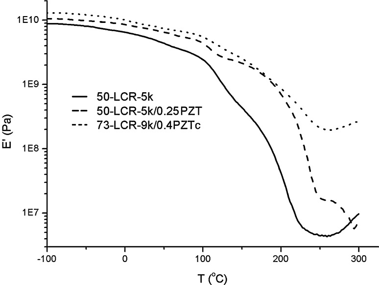
The thermo mechanical properties for some of the composites (50-LCR-5k/0.25PZT and 73-LCR-5k/0.4PZTc) and one (uncured) base polymer (50-LCR-5k) as derived by DMTA are plotted in Fig. 9. At room temperature the Young’s modulus varies between 5 GPa and 15 GPa, depending on PZT content and processing route. This high minimum value is due to the LCR nature of the base polymer as described by Knijnenberg et al. [11]. The figure confirms the good temperature dependence on the polymer. The composites always have a higher stiffness than the base polymer but exhibit similar temperature dependence, indicative of the good adhesion being maintained during heating. The temperature dependence of the elastic modulus of the other composites and the other base polymer was found to be similar to the curves presented here.
Fig. 9.
Thermo-mechanical properties of two PZT-LCR composites and one LCR base resin
Post-formability
As post-formability is a novel processing characteristic for these sensor materials no standardized tests exist yet. In order to demonstrate that the precursor sheet composites can be reshaped by thermal routes without losing their piezoelectric functionality, rectangular strips of 73-LCR-9k/0.4PZTc were pressed for 5 min at 270 °C in a U-shaped die. Initial thickness of the strip was 200 μm while the depth of displacement was about 600 μm. The conditions were below those leading to further crosslinking and samples were deformed in their plastic regime. The imposed shape was retained very well and no cracking was observed. More extensive and more controlled post-formability experiments are to be reported in a future publication, as insight in this property is paramount for easy processing of sensors made from this novel composite material. Figure 10 is a picture of a post-formed strip of PZT-LCR material.
Fig. 10.
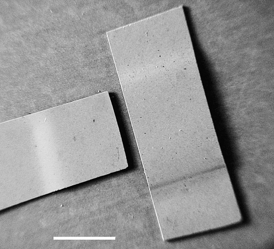
Demonstration of the post-formability ability of the composite. The white line represents 5 mm
Conclusions
A range of novel PZT-LCR composites have been produced. These composites possess a high piezoelectric voltage constant (g 33) qualifying the material attractive for sensor applications, for instance for impact detection or vibration detection in composite structures. A maximum value of 48 mV m/N was obtained but even higher values are expected when fine tuning processing and compositions. The dielectric and piezoelectric behaviour is well described by Yamada’s theory for piezoelectric properties for 0–3 composites. An excellent adhesion between polymer matrix and PZT particles was obtained, while processing remained relatively simple. The systems are potentially suitable as higher temperature sensor materials, for instance in automotive or aerospace applications. For composites manufactured in this research a maximum operating temperature of 170 °C was found before piezoelectric properties started to deteriorate. This loss in piezoelectricity is attributed to partial depolarisation of the PZT particles. The liquid crystalline thermosetting character of the polymer imparts a high temperature post-formability potential to the composites which offers great potential for shaping the final sensor into complex forms from sheet precursor material.
Acknowledgements
The authors acknowledge the supply of the PZT powder by Morgan Electro Ceramics and stimulating scientific discussions with Dr. W.A. Groen (Morgan Electro Ceramics). We thank Mr. P. Droppert (TU Delft) for the dielectric measurements and Mr. A. Knijnenberg (TU Delft) for technical advice and support in material processing.
References
- 1.Jaffe B, Cook WR, Jaffe H. Piezoelectric ceramics. New York: Academic; 1971. pp. 253–267. [Google Scholar]
- 2.Yamada T, Ueda T, Kitayama T. J Appl Phys. 1982;53:4328. doi: 10.1063/1.331211. [DOI] [Google Scholar]
- 3.Furukawa T, Ishida K, Fukada E. J Appl Phys. 1979;50:4904. doi: 10.1063/1.325592. [DOI] [Google Scholar]
- 4.Chan HLW, Chen Y, Choy CL. Ferroelectrics. 1995;9:207. doi: 10.1080/10584589508012925. [DOI] [Google Scholar]
- 5.Ploss B, Shin FG, Chan HLW, Choy CL (1998) 11th International symposium on applications of ferroelectrics (ISAF XI) proceedings p 299
- 6.Vekatragavaraj E, Satish B, Vinod PR, Vijaya MS. J Phys D: Appl Phys. 2001;34:487. doi: 10.1088/0022-3727/34/4/308. [DOI] [Google Scholar]
- 7.Malmonge LF, Malmonge JA, Sakamoto WK. Mat Res. 2003;6:469. doi: 10.1590/S1516-14392003000400007. [DOI] [Google Scholar]
- 8.Satish B, Sridevi K, Vijaya MS. J Phys D: Appl Phys. 2002;35:2048. doi: 10.1088/0022-3727/35/16/321. [DOI] [Google Scholar]
- 9.Furukawa T, Fujino K, Fukada E. Jap J Appl Phys. 1976;15:2119. doi: 10.1143/JJAP.15.2119. [DOI] [Google Scholar]
- 10.Sa-Gong G, Safari A, Jang SJ, Newnham RE. Ferroelectrics Lett. 1986;5:131. doi: 10.1080/07315178608202472. [DOI] [Google Scholar]
- 11.Knijnenberg A, Weiser ES, Stclair TL, Mendes E, Dingemans TJ. Macromolecules. 2006;39:6936. doi: 10.1021/ma060441o. [DOI] [Google Scholar]
- 12.Dingemans TJ, Weiser ES, Stclair TL; US Patent 6,939,940
- 13.Newnham RE, Skinner DP, Cross LE. Mat Res Bull. 1978;13:525. doi: 10.1016/0025-5408(78)90161-7. [DOI] [Google Scholar]
- 14.Jaffe B, Cook WR, Jaffe H. Piezoelectric ceramics. New York: Academic; 1971. pp. 142–143. [Google Scholar]
- 15.Jaffe B, Cook WR, Jaffe H. Piezoelectric ceramics. New York: Academic; 1971. p. 136. [Google Scholar]
- 16.Turcsanyi B, Pukanszky B, Tudos F. J Mat Sci Lett. 1988;7:160. doi: 10.1007/BF01730605. [DOI] [Google Scholar]
- 17.Pukanszky B. Composites. 1990;21:255. doi: 10.1016/0010-4361(90)90240-W. [DOI] [Google Scholar]


