

Abstract
Microwave (MW) ablation has emerged as a minimally invasive therapeutic modality and is in clinical use for treatment of unresectable tumors and cardiac arrhythmias, neuromodulation, endometrial ablation, and other applications. Components of image-guided MW ablation systems include high-power MW sources, ablation applicators that deliver power from the generator to the target tissue, cooling systems, energy-delivery control algorithms, and imaging guidance systems tailored to specific clinical indications. The applicator incorporates a MW antenna that radiates MW power into the surrounding tissue. A variety of antenna designs have been developed for MW ablation with the objective of efficiently transferring MW power to tissue, with a radiation pattern well matched to the size and shape of the targeted tissue. Here, we survey advances in percutaneous, endocavitary, and endoscopic antenna designs as an integral element of MW ablation applicators for a diverse set of clinical applications.
Keywords: microwave ablation, thermal ablation, cancer, antenna design, probe design, ablation applications
I. THERMAL ABLATION
Thermal ablation is the destruction of tissue by localized heating to elevated temperatures, typically in excess of 50°C. Its medical applications includes tumor destruction in the liver, lung, kidney, and other organs, disrupting conduction pathways for treatment of cardiac arrhythmias, neuromodulation by destroying nerves (e.g., renal denervation), and tissue reshaping.1–4 Heating can be achieved through a variety of energy sources, including: microwave (MW), laser, radiofrequency (RF) current, and ultrasound (US).5 Ablative effects can also be obtained by freezing, termed cryoablation, and irreversible electroporation, which is a non-thermal ablative modality using high-voltage pulsed electric fields.6,7 Technologies have been developed for delivering ablative energy via percutaneous, intracavitary, endovascular, endoscopic, laparoscopic, and open surgical approaches to a range of tissue targets. Suitable approaches for specific target sites are determined by factors such as the size, location within the body, accessibility, and biophysical properties of the targeted tissue. Figure 1 illustrates schema for thermal ablation devices that have been developed and are in clinical use in the liver, urethra, renal artery, and esophageal tract.8–10
FIG. 1:
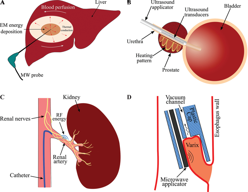
Examples of technologies for delivering ablative energy via (A) percutaneous, (B) intracavitary (adapted from Burtnyk et al.8), (C) endovascular (adapted from Fernández-Ruiz10), (D) endoscopic approaches (adapted from Sebek et al.9).
Regardless of the energy modality, the biologyical effects of tissue heating are a function of the intensity of heating and the time for which the tissue is exposed to that temperature. In general, the higher the temperature, the shorter the amount of heating time required to deliver ablative treatment. A review of mathematical models of thermal damage following heating is provided by Pearce.11
Of the various ablation technologies in clinical use, RF ablation devices have been most widely used, with major applications including treatment of cardiac arrhythmias and tumor ablation. The use of MW energy for thermal tissue ablation was first reported in the late 1970s, when several studies described monopolar MW antennas for surgical coagulation in soft tissues.12 To date, the vast majority of development of MW ablation technology has been focused on thermal ablation of large unresectable tumors in vascular organs such as the liver. Compared to RF ablation, MW ablation devices enable heating of larger tissue volumes. Researchers focused on optimizing needle-based MW applicators such as dipole, monopole, and coaxial slot antennas to provide large spherical ablation pattern. As reviewed in Bertram et al. and O’Rourke et al.,13,14 efforts were focused on suppressing the backward current on the surface of the coaxial cable outer conductor by adding chokes and sleeves as well as keeping the electric fields concentrated around the antenna tip antenna.15,16 Another technique was to create a better coupling between the antenna and the surrounding tissue by loading the antenna with a dielectric material with electrical permittivity closer to that of the tissue.17 Although these modifications improved the ablation pattern, there was still room to make the applicators thinner and less invasive. Thinner applicators were introduced by integrating a matching network into the coaxial cable, using an air-filled coaxial section at the end of a Teflon-filled coaxial line and integrating a balun on the coaxial cable outer conductor itself.18–20 The need for their use in medical applications other than hepatic cancer has led to some newer designs that offer directional heating pattern, making it possi-ble to ablate diseased tissues safely next to critical structures.21,22 Although antennas employing rigid coaxial feedlines have primarily been developed for tumor ablation, helix and spiral antennas have been integrated within flexible catheter-based devices for cardiac ablation and treatment of Barrett’s esopha-gus.23,24 MW energy may be delivered to the tissue through a coupling medium enclosed within a bal-loon surrounding the antenna. Small and localized ablation patterns have been achieved by using transmission-line-based applicators for collagen reshaping on the cornea, endometrial ablation, and bone drilling.25–27 Coaxial cable and circular waveguides can create a hotspot at their tip. One of the main requirements in minimally invasive ablation is the small diameter of the device. This has limited the design to coaxial applicators. However, applicability of printed circuit board technology in MW ablation has been investigated by choosing a higher operation frequency aiming for small ablation zone and designing dual-mode devices for dielectric measurement and ablation.28,29
The antenna is an integral element of a MW ablation device and has a significant impact on the ablation pattern. Here, we review MW ablation antenna designs that have been developed to address clinical needs for a diverse set of applications.
II. OVERVIEW OF MW ABLATION
A. Biophysics of MW Tissue Heating
Propagation of electromagnetic energy is determined by the dielectric permittivity and magnetic permeability of the medium within which the waves travel. Like many other materials, the relative magnetic permeability of most biological tissues is approximately equal to one. However, the dielectric permittivity varies widely among tissue types and is generally complex valued. The complex permittivity of tissue is often expressed in terms of relative permittivity and effective electrical conductivity (σ), which are defined as in Eq. (1):
| (1) |
where ω [rad/s] is the angular frequency and ϵ0 is permittivity of free space. The Poynting theorem shown in Eq. (2) describes the conservation of elec-tromagnetic energy:
| (2) |
where P is the Poynting vector, and E and H are electric and magnetic fields, respectively. The Poynting vector represents the directional energy flux of an electromagnetic field and is given by P = E × H. The real component of ∇ · P in Eq. (2) quan-tifies the ability of a material to store electrical and magnetic energy, whereas the imaginary component of ∇ · P determines how well electromagnetic energy is absorbed by a material. It is noted that effective conductivity [computed from imaginary part of in Eq. (1)] captures the contribution from time-varying electric fields (displacement current), specifically rotation of dipoles in polar materials as they realign with the orientation of the applied alternating electric field. In most biological tissues, the main contribution to losses at MW frequencies is the displacement current. The rotation of dipoles generates heat inside biological tissues, which is known as dielectric heating.30,31
Both relative permittivity and effective conductivity are dependent on frequency, temperature, and other factors in biological tissues such as water content. As an example, Fig. 2 shows the relative permittivity and effective conductivity of liver tissue over the frequency range 10 Hz to 100 GHz.32
FIG.2:
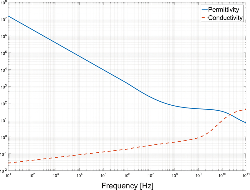
Dependence of liver dielectiric properties on frequency based on technology described by Gabriel et al.32
The electromagnetic wavelength in tissue can be calculated from the relative permittivity using the relationship. The wavelength is a particularly important parameter for antenna design; antennas are often efficient when their critical dimension is of the order of wavelength. The relatively ong wavelength (on the order of centimeters) in biological tissue places constraints on the minimum antenna size that can be employed for practical ablation applications. Electromagnetic wavelength in liver tissue as a function of frequency is shown in Fig. 3.
FIG. 3:
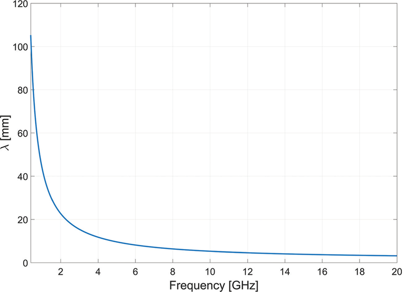
Electromagnetic wavelength in liver tissue versus frequency
B. MW Ablation Systems
A block diagram of an image-guided MW ablation system is shown in Fig. 4. In this system, power is transferred from a high-power MW source to the target tissue through an applicator. An imaging system assists the physician in locating the targeted tissue and positioning the applicator accordingly. The imaging system, as well as auxiliary sensors (potentially integrated within the applicator), may provide some assessment of the treatment progress, which the physician may use to adjust the treatment parameters. For example, in the case of percutaneous tumor ablation, changes in Hounsfield units observed on CT imaging may provide some assessment of the region where ablative energy is deposited. Other physical variables that may provide some assessment of treatment progress include antenna impedance mismatch (as assessed by changes in reflected power), temperature, and pressure. Selection of the treatment delivery parameters (e.g., applicator positioning, applied power level, and treatment duration) for individual treatments are most often selected based on the physician’s experience. Model-based treatment planning tools guiding ablation procedures are the subject of active research.33
FIG. 4:
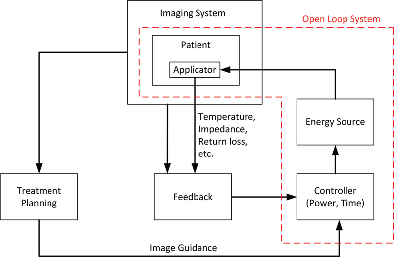
Components of an image-guided MW ablation system
Most MW ablation systems in clinical use operate at 915 MHz and 2.45 GHz. The rationale for selection of these frequencies is that they fall within industrial, scientific, and medical band and they exhibit larger penetration depth and less cable heating, which increases with frequency. However, there are some merits to higher frequencies as explored at 9.2 GHz, 10 GHz, 14.5 GHz, 900 MHz to 18 GHz, and 24 GHz.26,29,34–38 In Yoon et al.29 and Sawicki et al.,37 the effect of MW frequency on ablation zones was assessed using dipole and planar antennas. These studies suggested that thermal conduction has a more significant role in creation of the ablation zone at higher frequencies compared with low frequencies, where MW power absorption is dominant. Furthermore, the ablation zone dimensions remain comparable in size over frequency for constant input power and ablation duration, although the active length of the device becomes smaller as frequency increases. A smaller antenna could allow more flexible routing near organ boundaries or around major blood vessels. However, a drawback of using high frequencies is larger ohmic heating along the feed-line due to the smaller skin depth, which can lead to a teardrop ablation zone at high power levels.
Different components of the ablation system have been under investigation to achieve an effective treatment. Much effort has been focused on designing applicators capable of creating large spherical ablation patterns in highly vascular organs such as the liver or ablation patterns conformal to the organ under treatment. Some researchers have characterized thermal and electrical properties of different tissues and investigated the biological effects of different energy modalities to improve simulation models for device design. This would reduce the cost and number of iterations in the device designprocess. Incorporation of an imaging system capable of real-time monitoring of the ablation progress would be a significant step toward enabling delivery of adequate thermal doses to targeted tissues. Finding a parameter to estimate the growth of the ablation zone instead of an imaging system is another option to be employed as feedback. One example of a feedback parameter is tissue impedance change relative to its desiccation rate, as commonly employed in RF ablation systems.39
III. MW ABLATION APPLICATORS
The goal of thermal ablation procedures is to heat targeted tissue regions to ablative temperatures while minimizing damage to non-targeted tissue regions. Applicators for MW ablation consist of a feeding transmission line terminated by a radiating antenna; the electric field radiated by the antenna is absorbed in surrounding tissue regions leading to heating.
Because practical transmission lines are made of conductors and dielectrics with non-negligible attenuation, the transmission line heats up when MW power supplied from the generator passes through. The geometry of the radiating antenna, frequency of operation, and the electromagnetic properties of the surrounding media determine the spatial profile of the radiated electric field into tissue, as well as the applicator’s efficiency at transferring power from the feeding transmission line to the radiating antenna.
Antenna return loss (RL) represents the ratio of power delivered to the antenna to the power reflected back to the source due to impedance mismatch between the transmission line and antenna:
| (3) |
Although it is desirable to maximize RL, in practice, RL > 10 dB provides an approximate design goal, representing 90% of power transferred to the antenna. Inefficient applicators will require larger applied power levels at the transmission line input terminal to achieve the same ablation size as an efficient applicator. Attenuation within the feeding transmission line leads to heating of the applicator, which often requires the use of active cooling strategies to maintain applicator integrity and to minimize passive heating of tissue that may be in contact with the applicator. Therefore, highly efficient applicators are desirable because they reduce the burden on cooling of the feeding transmission line.
A typical cooling system integrated to the applicator consists of circulating coolant fluid through two inflow and outflow lumens. “Examples of coolant fluids include saline solution and pressurized CO2 gas.40,41 Advantages of cooling are sparing the healthy tissue along the feedline, increasing the sphericity of ablation zone by mitigating the backward heating, and higher power delivery. Figure 5 shows a cooling strategy on a dipole antenna. Cooling may be implemented using an arrangement of concentric tubes for coolant inflow/outflow. If the coolant used is electromagnetically lossy, then circulating the coolant to the distal tip of the radiating antenna will result in MW absorption within the fluid, coupling less power to the tissue and potentially reducing the efficacy of the cooling.
FIG. 5:
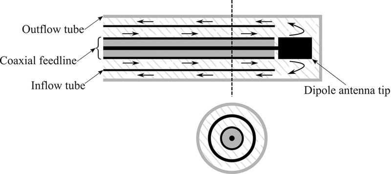
Integration of a cooling system to a coaxial dipole antenna. Arrows indicate direction of coolant flow.
The antenna geometry relative to the electromagnetic wavelength at the operating frequency also determines the pattern of the radiated electric fields. It is desirable to select antenna geometries that yield electric field radiation patterns that are well matched to the tissue regions targeted for ablation. Although the electromagnetic power absorbed is proportional to |E|2, thermal profiles in tissue are also affected by passive conduction of heat and cooling due to blood flow and these effects should be considered during antenna design optimization.42
The efficiency and ablation pattern of candidate MW applicator designs can be evaluated under a variety of experimental conditions. Antenna RL can be measured by immersing the antenna in a tissue mimicking load. A variety of tissue-mimicking phantoms with tunable dielectric properties have been reported in the literature.43,44 Measurement of the antenna’s specific absorption rate (SAR) pattern may be helpful for assessing the radiation pattern of an antenna, but neglects the effects of thermal conduction on ablation zone profiles.45 Furthermore, SAR measurements typically do not account for the changes in antenna radiation pattern due to temperature-dependent changes in tissue dielectric properties. Ablation devices are often characterized in ex vivo tissue. The size and shape of the ablation is defined by tissue discoloration at elevated temperatures.46 To account for effects of blood perfusion, which acts as a heat sink, ablation zones must be evaluated in an in vivo animal model or by emulating the perfusion using a perfusion chamber.47,48 Ablated tissue is resected after in vivo ablations for histopathologic analysis; viability stains may assist in accurate determination of the ablation zone boundary.
A. Early MW Ablation Applicators
Semi-rigid coaxial cables have been widely used as feeding transmission lines within MW ablation applicators. This is because their cylindrical geometry facilitates insertion within rigid catheters and antennas can be readily integrated by modifying the geometry of the distal tip of the cable. Ablation applicators are designed to fit within an insulating material (e.g., a rigid catheter) to facilitate insertion, prevent the device from adhering to the ablated tissue, provide protection and mechanical stability, and improve power coupling to the tissue. Figure 6 illustrates insulated coaxial dipole, monopole, and slot antennas that have been extensively characterized for moderate hyperthermia and thermal ablation.49–51
FIG. 6:
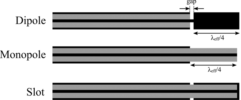
Early MW antennas for interstitial thermal therapy: dipole, monopole, and slot (black: metal, grey: dielectric)
Generic dipole antennas consist of two equal length conductors separated by a small gap where the feeding transmission line is connected. As illustrated in Fig. 6, the coaxial dipole antenna incorporates a λeffective/4 length of conductor separated from the cable, where λeffective represents the effective wavelength for a concentric multi-layered structure of an insulated conductor surrounded by electromagnetically lossy tissue.52 The effective wavelength is a function of the coaxial cable diameter, thickness of the insulating catheter and dielectric properties of the surrounding tissue and the catheter. For instance, the λeffective/4 length for liver tumor ablation could be around 10.9 mm at 2.45 GHz for a dipole made of UT-85 coaxial cable (0.085-inch outer diameter) inserted within a thin polyolefin heat-shrink tubing. The length of the gap is usually designed to be much smaller than the wavelength to approximate it as an infinitesimal source. The gap acts as an effective source for propagation of electromagnetic waves. The second leg of the dipole is formed by the section of the coaxial cable proximal to the gap. The differences in the length of these two legs leads to an unbalanced dipole antenna. The difference in construction of the dipole and slot is that, in the dipole, the distal end is a solid metallic cylinder, whereas, in the slot, it is a coaxial cable shorted at the end. The monopole antenna is formed by stripping a λeffective/4 section of the coaxial cable’s outer conductor.
Major shortcomings of these antennas are the dependence of the ablation profile and resonant frequency on the insertion depth of the device, backward heating, and non-spherical ablation profile. Current travels toward the antenna inside the coaxial cable on the inner conductor surface and inside surface of the outer conductor. A part of the current would travel back toward the MW source on the outer surface of the outer conductor due to unbalanced structure of coaxial cable. This current generates unwanted heat along the feed cable and decreases the sphericity of the ablation pattern. One effective solution to these limitations is the addition of a choke or sleeve to the outer conductor of the cable to suppress the backward currents and keep the power deposition localized to the radiating part of the antenna.15,16 Another solution to improve the ablation pattern sphericity is the addition of a cap and dielectric loading of the antenna radiating section with materials such as Teflon, alumina, or ceramic.17,53–55
Figure 7 shows incorporation of chokes, a sleeve, and a cap in the original antennas. The difference between a choke and a sleeve is the electrical connection of the choke with the coaxial cable outer conductor. A dielectric such as Teflon is usually used to hold the sleeve in place and to prevent electrical connection to the outer conductor. Length of a choke is usually λeffective/4, whereas that of sleeve is approximately λeffective/2.16 The sleeve/ choke is typically based a short distance from the antenna junction; optimization techniques for determining geometry of sleeve antennas are presented in Prakash et al.42,56 The principle of operation of antenna chokes is similar to that of baluns, which are commonly used with coaxial dipole antennas. It has been observed that adding a choke element may also improve antenna impedance matching.54,57 The principle of operation of a choke is similar to a balun in a coaxial dipole antenna. It has been also observed that addition of a choke also aids in impedance matching.54,57 One technique to localize the radiation of the antenna to the distal end of the applicator is to add a cap to tip of the antenna. The cap increases capacitance and may be implemented using a variety of shapes such as disk, ring, or arrow. Figure 7 also illustrates a design that employs a biopsy needle as both an introducer and a choke to obtain a thinner device.47,57,58
FIG. 7:
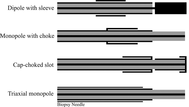
Examples of coaxial antennas with sleeve, choke, and cap and a monopole in a triaixal configuration (black: metal, grey: dielectric)
Another antenna design to improve the radiation localization with the goal of achieving a more spherical ablation pattern even without a choke is a multi-slot coaxial antenna.59–61 The multi-slot antenna is similar to the single-slot antenna shown in Fig. 6 except with more slots scattered along the coaxial cable. In a dual-slot antenna, an active choke is created by destructive interference of the phase of currents from the proximal and distal slots along the antenna shaft that suppresses the backward current and truncates the heating pattern.61,62
As an illustrative example, Fig. 8 depicts fabrication of a coaxial dipole antenna, with and without a sleeve. The simulated and measured return loss of the two antennas are compared in Fig. 9. The simulated and measured return loss of two dipole antennas, one with and another without the sleeve, are compared in Fig. 9. Both antennas exhibit a very wide bandwidth. Simulated power absorption and temperature profiles of the dipole antennas are shown in Fig. 10. Photographs of experimental ablation patterns of the two dipole antennas in ex vivo muscle tissue are also shown in Fig. 11.
FIG. 8:
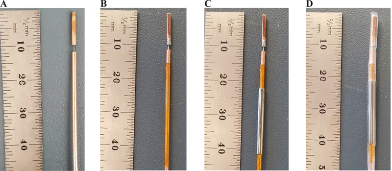
Fabrication steps of a dipole antenna with sleeve: (A) simple dipole, (B) addition of an insulation layer (polyimide), (C) addition of the metal sleeve, and (D) covering of the dipole with heat shrink
FIG. 9:
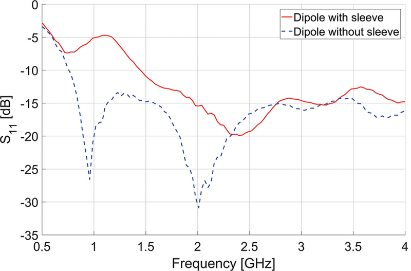
Measured reflection coefficients (S11) of dipole antennas with and without sleeve
FIG. 10:
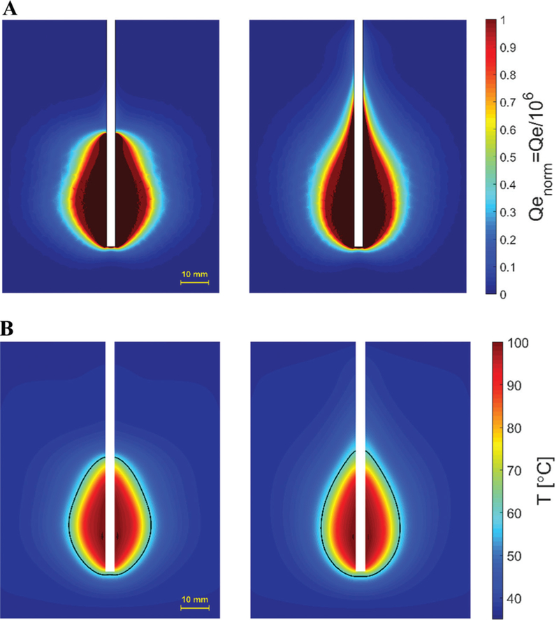
Simulated (A) power absorption profile and (B) temperature profiles of dipole antennas with (left) and without (right) sleeve. Estimated extent of the ablation zone is overlaid in black. (Pin = 60 W, duration = 2 minutes).
FIG. 11:
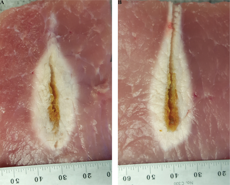
Example ablation patterns of dipole antennas (A) with and (B) without sleeve in ex vivo procine muscle (Pin = 60 W, duration = 2 minutes)
B. Reduced-Diameter MW Ablation Antennas
Although integration of chokes and caps improves the antenna performance by achieving highly localized SAR patterns, these elements make the applicator more invasive by increasing the overall diameter. Recent efforts have been focused on integrating the choke or sleeve within the coaxial cable. Figure 12 shows three different designs for suppressing the backward current. Figure 12a shows a balun-free design.18 The principle of this approach is to operate the antenna at the second resonant frequency where electrical length of the helical antenna is half a wavelength. The SAR pattern is then highly localized to the applicator tip as a result of a current minimum at the feed point of the helix. This current minimum provides a high feed impedance that acts as a natural choke and suppresses currents excited on the outer surface of the outer conductor. However, the input impedance creates a large mismatch between the coaxial feedline and antenna. This problem is resolved by integrating a quarter-wavelength transformer or 𝜋-matching network. These matching networks can be designed and implemented by choosing different dielectric materials such as air for the coaxial cable and by altering the thickness and diameter of the inner and outer conductor.
FIG. 12:
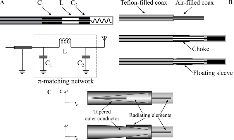
Techniques for reducing applicator diameter: (A) Matching network (adapted from Luyen et al.18); (b) reduced diameter by using a different dielectric material (adapted from Luyen et al.19); and (c) tapered balun (adapted from Luyen et al.20) (black: metal, grey: dielectric, white: air)
Figure 12b shows a technique for incorporating a choke or sleeve within the antenna without increasing its diameter.19 The technique utilizes an air-filled coaxial section at the end of the common Teflon-filled coaxial feedline with the goal of achieving a smaller diameter. Using air and Teflon permittivity to calculate the dimensions of a coaxial cable with 50 Ω characteristic impedance, a 30% smaller diameter is obtained for the same inner conductor diameter. A choke or sleeve can be implemented on the air-filled section of the coaxial to avoid increase in overall diameter of the applicator.
The main reason to use a choke or sleeve on a percutaneous MW ablation antenna is to suppress the backward currents on the outer surface of the outer conductor of the coaxial feedline. Backward currents exist due to the inherent unbalanced structure of the coaxial cable. By gradually changing the shape of the outer conductor to create a balanced transmission line, the backward current problem may be addressed. Figure 12c shows a dipole antenna design with a tapered balun.20 The outer conductor has been gradually tapered into two parallel strips that act as the second arm of the dipole. The first arm of the dipole is the extension of the inner conductor. In addition to achieving a highly localized SAR without using an external choke or sleeve, the tapered balun improves the antenna return loss by acting as a matching network. Further, the gradual taper of the balun increases the antenna bandwidth.
C. Directional Applicators
Most MW ablation applicators employ a needle-based design and yield an ovoid ablation pattern. In practice, the applicator is usually placed in the center of the targeted tissue and the ablation zone progresses radially outward. In cases when the target is next to critical structures, caution must be taken to prevent any damage to non-targeted tissues. One technique to overcome this adverse effect is fluid instillation between the target and adjacent tissue (hydrodisplacement) to protect vulnerable organs. The fluid such as dextrose 5% in water or saline increases the distance between the MW source and the target structure and further acts as a heat sink. This technique directs the energy primarily to sites away from where the fluid is instilled.63
Recently, a few antenna designs capable of restricting MW radiation to a preferred direction, approximately one half of the angular expanse, have been reported. Such applicators may be used for ablation of targets in proximity of critical structures without requiring any space for fluid displacement. Figure 13 shows two antenna designs with directional radiation patterns suitable for integration within rigid catheters/needles. A proof-of-concept device is shown in Fig. 13a.21 This design consists of a monopole antenna with water cooling incorporated through its shaft. The coaxial feedline is concentrically placed within two inner (water inflow) and outer (water outflow) tubes. The inner tube, made of metal, is cut into a semicylinder from the base of the monopole and extended beyond the tip of the monopole. This semicylinder would act as a reflector to direct the MWs to one side of the monopole antenna. The outer tube, made of dielectric (polyimide or PEEK), extends beyond the reflector and allows water to circulate back to the reservoir. The circulating water provides active cooling that mitigates heating along the feedline and makes the device less invasive by eliminating the need for choke or sleeve for backward heating. Additionally, water high electrical permittivity (𝜖r = 78 @ 2.45 GHz) reduces the wavelength, thereby limiting overall antenna radiating length.
FIG. 13:
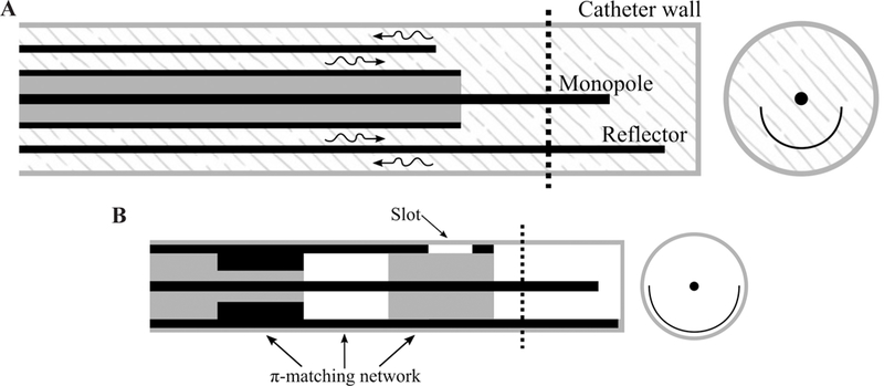
(A) Proof of concept (adapted from McWilliams et al.21) and (B) slot/monopole (adapted from Mohtashami et al.22) directional antennas (black: metal, grey: dielectric, white: air, patterned: water)
A thinner (2.5 mm) diameter with deeper radial ablation depth was obtained by modifying the monopole shape and reflector of Fig. 13a. The monopole antenna of McWilliams et al.21 is pushed toward the outer tube wall. The placement of the monopole antenna in close proximity to the outer tube wall and closer to the tissue would allow a larger portion of near-field MW energy to be coupled to the tissue and reduce the loss of energy to the cooling water. However, this placement increases the heating in the tissue behind the reflector. Shifting the reflector away from the monopole and toward the wall of the outer tube or using a parabolic shape reflector would help in increasing the radiation in the forward direction and provide a better shield in the reverse direction.64
Figure 13b shows an applicator that provides a directional heating pattern by incorporating a reflector and a slot into a monopole antenna.22 To limit the diameter of the device, the reflector is made by extending a portion of the coaxial cable’s outer conductor. The slot is also etched out next to the base of the monopole. The reflector is the main component in reducing the radiation behind the reflector. However, addition of the slot would create constructive and destructive electric fields in front of and behind the reflector, respectively. The slot improves the directionality of the applicator and suppresses the backward currents by creating a significant mismatch between the antenna and coaxial feedline. Although use of a slot leads to a thinner applicator (2.9 mm diameter) by eliminating the need for a balun, it creates a mismatch at the operation frequency that could be addressed by integrating a matching network into the coaxial cable. A π-matching network is implemented in the coaxial cable by using a different dielectric material inside the cable and changing the thickness of the outer conductor.
Sebek et al.9 integrated a modified version of the directional device of McWilliams et al.21 shown in Fig. 13a into a standard endoscopic cap for the application of treating esophageal varices (see Fig. 1d). The study investigates feasibility of using MW ablation for treating esophageal varices with the goal of achieving a safer and more effective treatment compared with endoscopic variceal ligation. A suction mechanism similar to variceal ligation captures the vessel by creation of a vacuum. When the vessel is sucked into the cap, the MW antenna located in the wall of the cap delivers MW energy to coagulate blood and seal the vessel. The antenna consists of a water-cooled monopole with a reflecting element. The monopole has been angled to improve the energy deposition to the vessel while sparing the surface. The distal end of the reflector has been formed into a hood to guide the water flow toward the backward flow channel. This would reduce the likelihood of air bubble formation that may come out of solution as the water trapped at the distal tip is heated.
A photo of a fabricated directional device is shown in Fig. 14. Simulated normalized power absorption profiles for a conventional monopole antenna compared with a directional antenna are shown in Fig. 15. Experimental ablation patterns for both antennas are shown in Fig. 16. These images illustrate the ability of the directional antennas to restrict ablation to approximately one-half of the angular expanse.
FIG. 14:
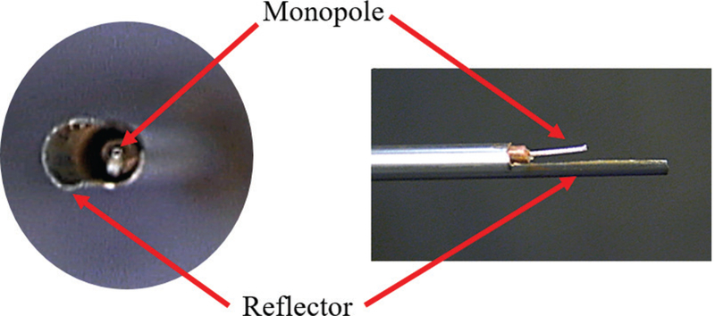
Example of a fabricated directional monopole antenna without the outflow polyimide tube (courtesy of Pegah Faridi)
FIG. 15:
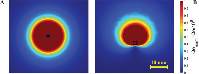
Example power absorption profiles of: (A) a conventional antenna and (B) a directional antenna
FIG. 16:
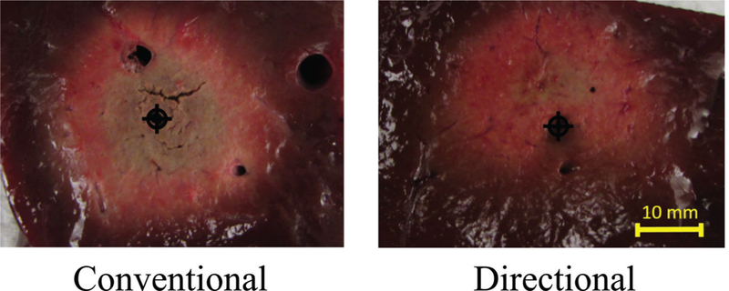
Comparison of directional and conventional monopole antenna ablation patterns in liver tissue
D. Helix and Spiral Antennas
The helical antenna is a basic antenna made of a wire wound in the form of a helix. The helix is usually connected to the inner conductor of a coaxial transmission line with the coaxial cable outer conductor as the ground. Helical antennas can be operated in axial and normal modes. When the helix diameter and spacing of the turns are comparable to the wavelength of the operation frequency, its maximum radiation intensity is along the axis of the helix. This end-fire radiation pattern could be obtained by adjusting the circumference of the each turn to the order of one wavelength and spacing between turns to approximately one-quarter of a wavelength. In the normal mode, the maximum radiation of the antenna is in the plane normal to the helix and minimum along its axis. This mode is achieved when diameter and spacing between turns are small compared with the wavelength.65
Helical antennas for thermal therapy applications were originally designed and experimentally evaluated for hyperthermia applications. Figure 17 shows three variations of helical antennas investigated by Satoh and Stauffer.66 The antennas were constructed by stripping off part of the outer conductor from one end of the coaxial cable. Coils made of copper wire were installed on the dielectric of the coaxial cable. In the helical coil-connected (HCC) variation, the distal end of the coil is electrically connected to the coaxial cable inner conductor and its proximal end is shorted to the outer conductor. In the helical coil-separated (HCS) variation, only the distal end is connected to the coaxial cable inner conductor. In the helical coil-open (HCO) variation, only the proximal end is shorted. HCC configuration has been analytically characterized by Mirotznik et al.67 and investigated by Reeves et al.23 for the treatment of Barrett’s esophagus. Liu et al.68 investigated the HCO configuration at 433 and 915 MHz. HCS has also been implemented for ablation of atrioventricular junction by Langberg et al.69 The number of the turns, length of the radiating part, and connection configuration of the coil are factors that can be optimized to obtain a desirable heating pattern.65 The advantages of the helical antenna over a simple dipole antenna are a stable heating pattern regardless of the insertion depth and a uniform heating pattern along the helix axis with limited radial penetration.
FIG. 17:
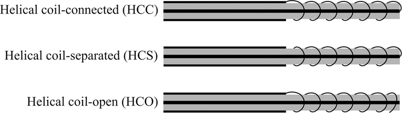
Variations of helical antenna (adapted from Satoh et al.66) (black: metal, grey: dielectric)
In Gu et al.,24 a spiral antenna is proposed for cardiac ablation. The advantage of a spiral antenna is its radiation pattern maximum normal to its surface. The spiral antenna can be modeled as a large circular loop. The excited fields by currents on the loop add up constructively inside the loop and cancel out each other outside the loop. Therefore, the radiation pattern of the spiral antenna, similar to that of the loop, makes it a good candidate for creating a planar heating profile when placed on the tissue surface. The resonant frequency of the spiral is dependent on the length of the antenna and the thickness and material of its dielectric coating. In another implementation, the spiral antenna is deployed inside a balloon inflated with a low-loss, low-dielectric-constant fluid such as air or nitrogen.70 The fluid not only prevents heating of the blood within the heart chamber, it also delivers more power to the heart tissue when less fluid is in front of the spiral than behind it.
E. Transmission-Line-Based Devices
For applications beyond oncology, it may be desirable to create small, localized ablation patterns. This may be achieved by employing open-ended transmission lines such as coaxial cables and waveguides. Fundamentally, an antenna plays the role of a matching network for coupling energy from a transmission line to a medium. Antennas are designed to provide a desirable radiation pattern for the corresponding application. Nonetheless, open-ended transmission lines are capable of radiation without an antenna. Swicord et al. have calculated the energy deposition pattern at the tip of an open-ended coaxial probe and shown that the total power is absorbed within a hemispherical region around the tip.71 Devices capable of delivering this energy deposition pattern have been applied to cornea reshaping for correcting hyperopia, keratoconus, or myopia in Trembly et al.25 An open-ended coaxial probe with an integrated cooling system is positioned in proximity of the cornea. MW energy is used to elevate the temperature to 55–58°C to shrink the cornea stroma permanently. The stroma is the central, thickest layer consisting of collagen fibers. Although the region of shrinkage is a disk approximately 1 mm in diameter, the enforced cooling spares the surface to a depth of 0.6 mm. The cooling is integrated to the transmission line by using a hollow inner conductor. The shrinkage results in a flattened cornea that leads to correction of keratoconus.
Jerby et al. harnessed the capability of an open-ended coaxial cable to concentrate energy in a small hotspot to implement a MW drill.27 The inner conductor of the coaxial cable is extendable. When extended, the open-ended coaxial cable turns into a monopole antenna that functions as the drill bit (Fig. 18). The MW drill can be used for bone drilling applications.72 First, the coaxial cable creates a confined hotspot under its tip. The hotspot increases the dielectric losses on the bone in a thermal runaway process that produces a soft or molten spot for penetration of the extendable inner conductor deeper. An advantage of the MW drill is that there is no rotating part involved in the process and it does not produce debris. Further, the generated heat under the drilling tip may immediately fuse bone vasculature, thereby eliminating hematomas.
FIG. 18:
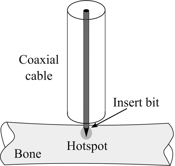
MW bone drill (adapted from Eshet et al.69)
In Hodgson et al.,26 an open-ended circular waveguide was utilized for endometrial ablation. Endometrial ablation is an alternative option to hysterectomy for the treatment of heavy menstrual bleeding. The open-ended waveguide applicator can produce a local hemispherical ablation zone with a radius of 5–6 mm. The applicator is translated inside the uterine cavity in a point-to-point fashion to completely ablate the endometrium layer. An 8 mm diameter device was achieved by choosing an operation frequency of 9.2 GHz and using a dielectric inside the waveguide instead of air. The applicator and how it creates a hotspot inside an egg white phantom are shown in Fig. 19. The dielectric has been extended beyond the waveguide tip and formed in a half circle to prevent perforation of the uterine tissue. The four wires around the tip are temperature sensors. Figure 19b shows the tip of the device prior to energizing the device and Fig. 19c shows 5 mm coagulated egg white around the tip.
FIG. 19:
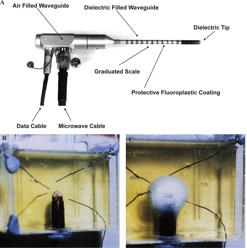
Waveguide applicator for endometrial ablation. (A) 9.2 GHz circular waveguide applicator for endometrial ablation in egg white (B) before and (C) after ablation. (Reprinted with permission from John Wiley and Sons, Copyright 2005.26)
F. Printed Planar Applicators
Coaxial-based antennas are the dominant class of applicators for MW ablation due to their symmetric and minimally invasive profiles. Although printed circuit board technologies such as microstrips provide the freedom to design antennas with diverse ablation patterns, achieving a practical device with an overall diameter less than 3 mm is not feasible at common MW ablation frequencies of 915 MHz and 2.45 GHz due to the large wavelength. In Colebeck et al., a slot antenna was printed on the back side of a microstrip line with ultrawideband characteristic.72 The device is capable of creating ablation zones at 915 MHz, 2.45 GHz, and 5.8 GHz. However, the overall width of the device is 5.5 mm, making it unsuitable for most clinical MW ablation applications.
Operation at higher frequencies allows for designing applicators with practical dimensions due to shorter wavelength of higher frequencies. Assessment-treatment dual-mode applicators have been developed based on open-ended planar coaxial aperture structure.28,29 In the assessment mode, broadband dielectric properties of the tissue in contact with the aperture is measured. In the treatment mode, power is delivered to the tissue for ablation at 18 GHz. The goal of such a device is to first distinguish malignant tissues from normal ones and then switch to treatment mode to destroy the tumor. A very compact and cost-effective MW ablation device was implemented by Kim et al.74 by integrating an entire MW generator consisting of a voltage-controlled oscillator, a driver amplifier, and a high-power am plifier plus directional coupler and power detectors to a similar dual-mode device in monolithic MW integrated circuits technology. Figure 20 shows another dual-mode applicator consisting of two oval split ring resonators (SRRs) printed on the back side of a coplanar waveguide (CPW).75 The SRR is coupled to the CPW line and is modeled as an LC resonant circuit. Resonant frequency of the SRR is a function of its dimensions and the material it is in contact with. The unloaded resonance frequency of the SRR is 12 GHz. The resonance frequency would be different for malignant and normal tissues. Figure 21a shows measured transmission coefficient of the SRR when loaded with phantoms mimicking normal and tumorous tissues. A shift in frequency of Δf = 350 MHz has been observed. When a tumor is detected, the treatment mode is activated and ablation is performed at the resonance frequency. Figure 21b-21e shows the simulated and experimental ablation zone of the SRR. In general, the dual-mode applicators are capable of creating ablation zones with input powers as small as 2 W; however, their ablation zone is limited to malignancies smaller than 20 mm.29
FIG. 20:
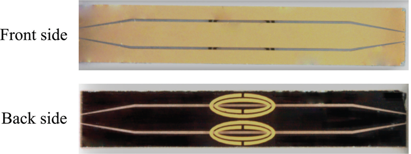
Dual-mode applicators consisting of oval SRR on the back side of a CPW. (Reprinted from Reimann et al. under a Creative Commons Attribution 4.0 International license: http://creativecommons.org/licenses/by/4.0/.75)
FIG. 21:
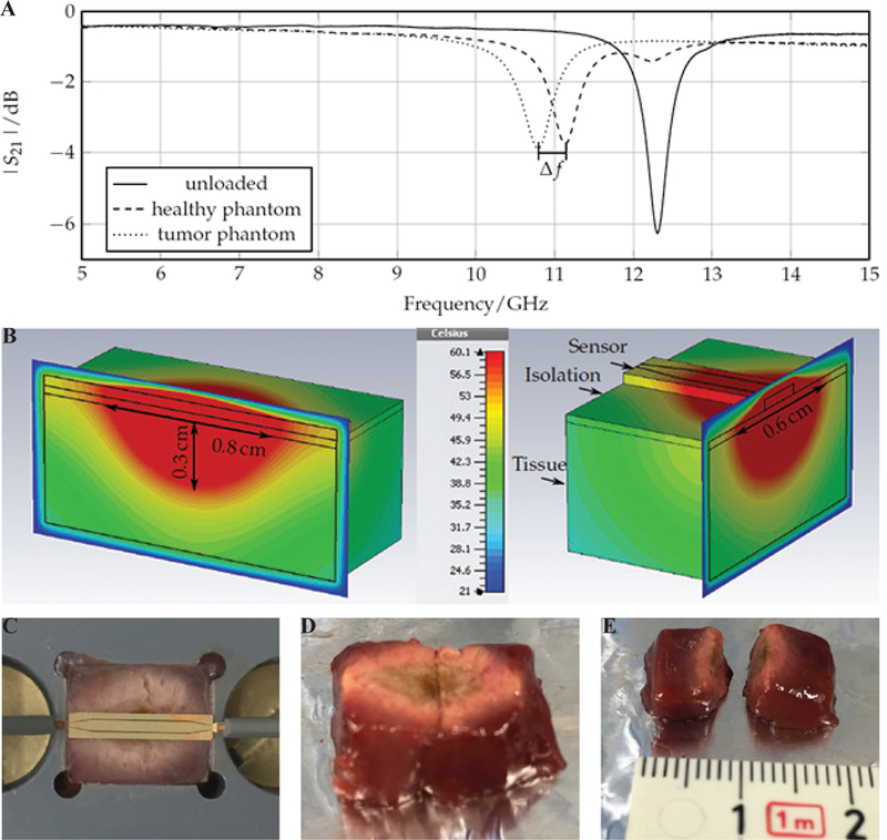
Performance of the dual mode SRR sensor of Reimann et al.75 Shown is the frequency shift in the: (A) assessment mode, (B) simulated ablation zone, and (C-E) experimental ablation zone in liver tissue in treatment mode. (Reprinted from Reimann et al. under a Creative Commons Attribution 4.0 International license: http://creativecom-mons.org/licenses/by/4.0/. 75)
Figure 22a shows a conceptual design of an array of two planar dipoles loaded with two surface-mounted capacitors on each arm.76 The dipoles are printed back to back and fed by a stripline. The idea is to obtain the desired ablation pattern by controlling the current distribution on each dipole through optimizing parameters such as the capacitance values, capacitor positions along the arms, and the feed point along the length of the dipole.
FIG. 22:
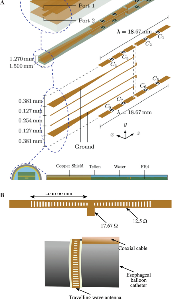
Array of two planar dipoles loaded with capacitors (A) (reprinted with permission from AIP Publishing, Copyright 201776) and (B) a traveling wave antenna (adapted from Hancock et al.35)
The applicability of a traveling wave antenna structure for Barrett’s esophagus has been investigated by Hancock et al.35 The goal is to create a band of controlled heating around the sphincter of esophagus to give controlled tightening. As shown in Fig. 22b, a series of slots are created on the ground plane of a microstrip line on a flexible substrate. By adjusting the size of each slot, uniform power coupling from the microstrip line to slots is achieved. This leads to uniform heating along the microstrip line. Two 30- slot structures have been fed by a coaxial cable in a “T” arrangement to have enough length for creating a band of 270° ablation zone. An operation frequency of 14.5 GHz has been selected to have a very shallow heating, thereby preventing muscle damage or perforation. For deployment inside the esophagus, the antenna has been attached to the outer surface of a balloon. The balloon will be inserted into esophagus through the instrument channel of a gastroscope in deflated form and will be inflated by filling the balloon with air or a liquid such as saline solution.
In a preclinical study, efficacy of a resonant planar structure integrated to a electrosurgical device has been investigated for endoscopic procedures.77 The device uses RF energy to cut and MW energy to coagulate and injects fluids to raise the lesion from the wall of the body lumen. The MW coagulator is a half wavelength microstrip line resonating at 5.8 GHz with dimensions of 2 and 8.66 mm for width and length, respectively. The top and bottom plates of the microstrip also act as the bipolar RF scalpel. The selected frequency of operation provides well-controlled coagulation depth.
G. Additional Designs
Although the common radiation pattern of MW ablation applicator is omnidirectional, other designs have been developed with different radiation patterns for applications such as snoring treatment, tumor ablation, non-contact circumferential endocardial ablation, and global endometrial ablation (Fig. 23).78–81
FIG. 23:
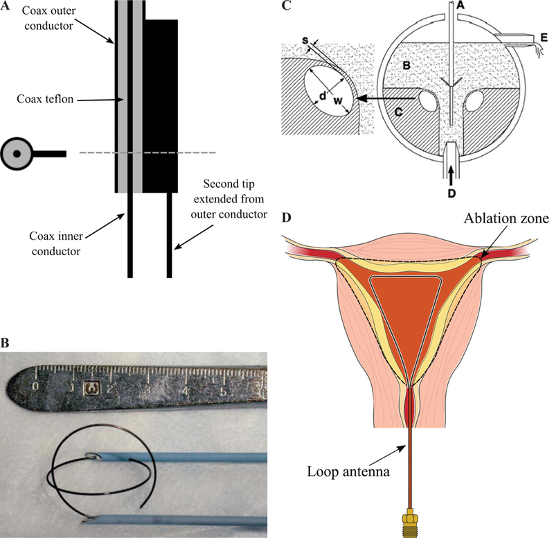
Two-prong fork device for treatment of snoring (A) (adapted from Cresson et al.78), double loop applicator (B) (reprinted with permission from Springer Nature, Copyright 200579), drooped ground monopole antenna (C) (reprinted with permission from John Wiley and Sons, Copyright 201580), and loop antenna for global endometrial ablation (D) (adapted from Fallahi et al.81)
In Cresson et al.,78 a two-prong fork made of coaxial cable was developed for snoring treatment. Figure 23a shows that one prong of the applicator is the extension of the coaxial cable inner conductor and the other one is a needle electrically connected to the coaxial cable outer conductor. This configuration would create a hotspot at the tip of the prongs while less heat is generated on the proximal end. The treatment goal of the device is to create a deep-seated fibrous scar in the soft palate tissue while sparing its surface by constraining the temperature. Ablation would change the soft palate to a fibrous scar that reduces vibratory capacity of the soft palate, thereby decreasing snoring.
Most of the implemented applicators for MW ablation of tumors are inserted into the center of the tumor and create an outward growing ablation zone to cover the whole tumor. In Shock et al.,82 a monopole antenna was suggested that takes a loop form when deployed (Fig. 23b). With this design, the tumor is encircled by the loop and is heated from the outside in. This may help in rapid truncation of the blood supply to minimize the blood heat sink effect. Further, the loop configuration would decrease tumor recurrence due to malignant cell proceeding during placement of needle form applicators because it is positioned next to the tumor. It is noted that, for complete coverage of the tumor, more than one applicator would be required due to less symmetric ablation pattern of the loop. Some disadvantages of the loop design is the more complicated targeting procedure of the tumors. Moreover, the loop is energized during deployment for easier placement, which can cause complications if it hits surrounding critical organs.82
A monopole with drooping ground radial wires has been implemented for noncontact circumferential endocardial ablation.80 As shown in Fig. 23c, the design target is to create a circumferential ablation pattern in the antrum of the pulmonary vein for isolation of the source of atrial fibrillation. Theoretically, the addition of four 45° drooped radial wires electrically connected to the outer conductor provides a pure resistive 50 Ω input impedance. Radial wires usually have a length of λeffective/4 and play the role of a ground plane. The radiation pattern of this antenna is above its ground plane. In other words, the radiation pattern is tilted toward the monopole arm and is slightly directional. This design takes advantage of the pulmonary vein flow for keeping the surface of the myocardial tissue cool.
Figure 23d shows a loop antenna inserted to the uterine cavity for globally ablating its inner lining, the endometrial layer, as a treatment for heavy menstrual bleeding.81 The loop consists of an extension of the inner conductor of a coaxial cable that is electrically connected to the coaxial cable outer conductor at its tip. The large loop antenna is resonant at a perimeter of one wavelength and changing its shape does not appreciably change the loop resonant frequency. The loop is inserted into the uterine cavity in an endocervical approach and deployed inside the cavity. The small diameter of the device does not require any dilation of the cervix. The loop conforms to the anatomy of the uterine cavity and create a planar ablation pattern. MW energy is majorly delivered along the loop wire, whereas the center of the loop is ablated through thermal conduction. Simulated and experimental ablation patterns shown in Fig. 24 confirms the creation of planar ablation patterns in the shape of the loop. Ablation depths at different cuts are also shown in Fig. 24.
FIG. 24:
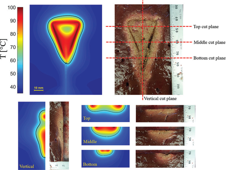
Simulated and experimental ablation pattern of a loop antenna with planar heating. Estimated extent of the ablation zone (60ºC isotherm) are overlaid on the simulated temperature profiles.
H. Alternative Ablation Pattern Control Techniques
The ablation pattern of MW applicators is primarily determined by the antenna structure. Alternative techniques to shape or tailor the antenna pattern have been incorporation of cooling, use of balloon, shifting to higher frequencies, and employing multiple devices in an array configuration.
Use of a balloon is an effective technique in intracavitary applications such as Barrett’s esophagus, renal denervation, benign prostate hyperplasia, and cardiac ablation.70,83–85 While the MW antenna is held in the center of the balloon, the balloon is inflated and filled with a coupling material such as saline or gel. These materials provide more efficient coupling of power from the antenna to the tissue compared with air because their electrical properties are similar to body tissues. In Qian et al.,84 deep circumferential heating is reported while sparing the transmural arterial wall in renal denervation application.
When treating large target volumes (e.g. tumors with diameter > 3 cm), a single applicator may not be able to provide a sufficiently large zone of ablation.86 The heat sink effect of local blood flow is the main reason for this limitation, which can increase the chances of incomplete ablation and risk of tumor recurrence. Therefore, the use of multiple applicators has been proposed to achieve a larger ablation volume. An SAR pattern of arrays of four antennas in square configuration has been investigated for different antenna types by Ryan et al.45 Helical antenna in square and crescent array form has been investigated by Sherar et al.87 for prostate cancer thermal therapy. The feasibility of using triple MW antennas simultaneously in the treatment of liver tumors intraoperatively has been shown by Simon et al.88 An array of multiple antennas may not create a sphere cal ablation zone, but the final ablation pattern can adequately cover the tumor by precise placement of the antenna elements.
IV. SUMMARY
There has been considerable interest in the development of MW ablation technology for a range of clinical indications. A critical component of MW ablation systems is the applicator, which includes an antenna for coupling applied MW power from a generator to the targeted tissue. Here, we have reviewed MW antennas designed for site-specific thermal ablation of tissue. The use of active cooling strategies for minimizing unintended heating along the feeding transmission line and antenna chokes/ sleeves and cooling for adjusting the length of ablation zones were discussed. Ongoing developments incorporating sensors for assessing treatment progress may yield improved control of MW thermal ablation zones.
ACKNOWLEDGMENT
We gratefully acknowledge support from the National Institutes of Health through Grant R01CA218357.
REFERENCES
- 1.Chu KF, Dupuy DE. Thermal ablation of tumours: biological mechanisms and advances in therapy. Nat Rev Cancer. 2014;14(3):199–208. [DOI] [PubMed] [Google Scholar]
- 2.Rey S, Levine S. an overview of cardiac ablation. J Clin Exerc Physiol. 2017;6(2):29–35. [Google Scholar]
- 3.Verloop W, Voskuil M, Doevendans P. Renal denervation: a new treatment option in resistant arterial hypertension. Neth Heart J. 2013;21(2):95–98. [DOI] [PMC free article] [PubMed] [Google Scholar]
- 4.Choby GW, Hwang PH. Emerging roles of coblation in rhinology and skull base surgery. Otolaryngol Clin North Am. 2017;50(3):599–606. [DOI] [PubMed] [Google Scholar]
- 5.Ahmed M, Brace CL, Lee FT Jr, Goldberg SN. Principles 20. of and advances in percutaneous ablation. Radiology. 2011;258(2):351–369. [DOI] [PMC free article] [PubMed] [Google Scholar]
- 6.Baust JG, Gage AA, Baust JM. Principles of cryoablation In: Abramovits William, Graham Gloria, Yaron 21. Har-Shai, Renata Strumia, editors. Dermatological cryosurgery and cryotherapy. New York: Springer; 2016. p. 9–16. [Google Scholar]
- 7.Jiang C, Davalos RV, Bischof JC. A review of basic to clinical studies of irreversible electroporation therapy. IEEE Trans Biomed Eng. 2015;62(1):4–20. [DOI] [PubMed] [Google Scholar]
- 8.Burtnyk M, Hill T, Cadieux-Pitre H, Welch I. Magnetic resonance image guided transurethral ultrasound prostate 23. ablation: a preclinical safety and feasibility study with 28-day followup. J Urol. 2015;193(5):1669–1175. [DOI] [PubMed] [Google Scholar]
- 9.Sebek J, Curto S, Eaton-Evans J, Bouchier-Hayes J, Ruvio G, Ganta C, Beard W, Buttar N, Song LWK, Prakash P Feasibility assessment of microwave ablation for treating esophageal varices. J Med Devices. 2017; 11(3):031013. [Google Scholar]
- 10.Fernández-Ruiz I Renewed hopes for renal denervation in hypertension. Nat Rev Cardiol. 2018. August;15(8):439. [DOI] [PubMed] [Google Scholar]
- 11.Pearce JA. Models for thermal damage in tissues: processes and applications. Crit Rev Biomed Eng. 2010; 38(1):1–20. [DOI] [PubMed] [Google Scholar]
- 12.Osaka A Use of microwave radiation in surgery and cancer therapy. J Microw Power. 1978;13(2):155–161. [DOI] [PubMed] [Google Scholar]
- 13.Bertram JM, Yang D, Converse MC, Webster JG, Mahvi DM. A review of coaxial-based interstitial antennas 28. for hepatic microwave ablation. Crit Rev Biomed Eng. 2006;34(3):187–213. [DOI] [PubMed] [Google Scholar]
- 14.O’Rourke AP, Haemmerich D, Prakash P, Converse MC, Mahvi DM, Webster JG. Current status of liver tumor ablation devices. Expert Rev Med Devices. 2007;4(4): 523–537. [DOI] [PubMed] [Google Scholar]
- 15.Saito K, Hosaka S, Okabe S, Yoshimura H, Ito K. A proposition on improvement of a heating pattern of an antenna for microwave coagulation therapy: Introduction 30. of a coaxial-dipole antenna. Electron Commun Jpn Part Commun. 2003;86(1):16–23. [Google Scholar]
- 16.Yang D, Bertram JM, Converse MC, O’Rourke AP, Webster JG, Hagness SC, Will JA, Mahvi DM. A floating sleeve antenna yields localized hepatic microwave ablation. IEEE Trans Biomed Eng. 2006;53(3):533–537. [DOI] [PubMed] [Google Scholar]
- 17.Nevel RD, Arndt GD, Raffoul GW, Carl JR, Pacifico A. Microwave catheter design. IEEE Trans Biomed Eng. 33. 1998;45(7):885–890. [DOI] [PubMed] [Google Scholar]
- 18.Luyen H, Hagness SC, Behdad N. A balun-free helical antenna for minimally invasive microwave ablation. IEEE Trans Antennas Propag. 2015;63(3):959–965. [Google Scholar]
- 19.Luyen H, Hagness SC, Behdad N. Reduced-diameter designs of coax-fed microwave ablation antennas equipped with baluns. IEEE Antennas Wirel Propag Lett. 2017;16:1385–1388. [Google Scholar]
- 20.Luyen H, Hagness SC, Behdad N. A minimally invasive coax-fed microwave ablation antenna with a tapered balun. IEEE Trans Antennas Propag. 2017;65(12):7280–7287. [Google Scholar]
- 21.McWilliams BT, Schnell EE, Curto S, Fahrbach TM, Prakash P. A directional interstitial antenna for microwave tissue ablation: Theoretical and experimental investigation. IEEE Trans Biomed Eng. 2015;62(9):2144–2150. [DOI] [PubMed] [Google Scholar]
- 22.Mohtashami Y, Hagness SC, Behdad N. A hybrid slot/ monopole antenna with directional heating patterns for microwave ablation. IEEE Trans Antennas Propag. 2017;65(8):3889–3896. [Google Scholar]
- 23.Reeves J, Birch M, Munro K, Collier R. Investigation into the thermal distribution of microwave helical antennas designed for the treatment of Barrett’s oesophagus. Phys Med Biol. 2002;47(19):3557–3564. [DOI] [PubMed] [Google Scholar]
- 24.Gu Z, Rappaport CM, Wang PJ, VanderBrink BA. A 2 1/4-turn spiral antenna for catheter cardiac ablation. IEEE Trans Biomed Eng. 1999;46(12):1480–1482. [DOI] [PubMed] [Google Scholar]
- 25.Trembly BS, Keates RH. Combined microwave heating and surface cooling of the cornea. IEEE Trans Biomed Eng. 1991;38(1):85–91. [DOI] [PubMed] [Google Scholar]
- 26.Hodgson DA, Feldberg IB, Sharp N, Cronin N, Evans M, Hirschowitz L. Microwave endometrial ablation: development, clinical trials and outcomes at three years. BJOG Int J Obstet Gynaecol. 1999;106(7):684–694. [DOI] [PubMed] [Google Scholar]
- 27.Jerby E, Dikhtyar V, Aktushev O, Grosglick U. The microwave drill. Science. 2002;298(5593):587–589. [DOI] [PubMed] [Google Scholar]
- 28.Kwon K, Lim S, Cho S, Yoon J, Cho J, Cheon C, Kwon Y Planar type probe with multiple-polarization response for in-vivo permittivity measurements of heterogeneous biological tissues. IEEE Microw Wirel Compon Lett. 2006;16(1):1–3. [Google Scholar]
- 29.Yoon J, Cho J, Kim N, Kim D-D, Lee E, Cheon C, Kwon Y. High-frequency microwave ablation method for enhanced cancer treatment with minimized collateral damage. Int J Cancer. 2011;129(8):1970–1978. [DOI] [PubMed] [Google Scholar]
- 30.Brace CL. Microwave tissue ablation: biophysics, technology, and applications. Crit Rev Biomed Eng. 2010;38(1):67–78. [DOI] [PMC free article] [PubMed] [Google Scholar]
- 31.Prakash P Theoretical modeling for hepatic microwave ablation. Open Biomed Eng J. 2010;4:27–38. [DOI] [PMC free article] [PubMed] [Google Scholar]
- 32.Gabriel S, Lau RW, Gabriel C. The dielectric properties of biological tissues: III. Parametric models for the dielectric spectrum of tissues. Phys Med Biol. 1996;41(11):2271. [DOI] [PubMed] [Google Scholar]
- 33.Deshazer G, Hagmann M, Merck D, Sebek J, Moore KB, Prakash P. Computational modeling of 915 MHz microwave ablation: comparative assessment of temperature-dependent tissue dielectric models. Med Phys. 2017;44(9):4859–4868. [DOI] [PubMed] [Google Scholar]
- 34.Luyen H, Gao F, Hagness SC, Behdad N. Microwave ablation at 10.0 GHz achieves comparable ablation zones to 1.9 GHz in ex vivo bovine liver. IEEE Trans Biomed Eng. 2014;61(6):1702–1710. [DOI] [PubMed] [Google Scholar]
- 35.Hancock CP, Dharmasiri N, Duff CI, White M. New microwave antenna structures for treating gastro-oesophageal reflux disease (GERD). IEEE Trans Microw Theory Tech. 2013;61(5):2242–2252. [Google Scholar]
- 36.Hancock CP, Dharmasiri N, White M, Goodman AM. The design and development of an integrated multi-functional microwave antenna structure for biological applications. IEEE Trans Microw Theory Tech. 2013;61(5):2230–2241. [Google Scholar]
- 37.Sawicki JF, Shea JD, Behdad N, Hagness SC. The impact of frequency on the performance of microwave ablation. Int J Hyperthermia. 2017;33(1):61–68. [DOI] [PubMed] [Google Scholar]
- 38.Komarov VV. Numerical study and optimization of interstitial antennas for microwave ablation therapy. Eur Phys J Appl Phys. 2014;68(1): 10901. doi: 10.1051/epjap/2014140175. [DOI] [Google Scholar]
- 39.Bongers MY. Second-generation endometrial ablation treatment: Novasure. Best Pract Res Clin Obstet Gynaecol. 2007;21(6):989–994. [DOI] [PubMed] [Google Scholar]
- 40.Kuang M, Lu MD, Xie XY, Xu HX, Mo LQ, Liu GJ, Xu ZF, Zheng YL, Liang JY Liver cancer: increased microwave delivery to ablation zone with cooled-shaft antenna-experimental and clinical studies. Radiology. 2007; 242(3):914–924. [DOI] [PubMed] [Google Scholar]
- 41.Knavel EM, Hinshaw JL, Lubner MG, Andreano A, Warner TF, Lee FT Jr, Brace CL. High-powered gas-cooled microwave ablation: shaft cooling creates an effective stick function without altering the ablation zone. Am J Roentgenol. 2012;198(3):W260–W265. [DOI] [PMC free article] [PubMed] [Google Scholar]
- 42.Prakash P, Deng G, Converse MC, Webster JG, Mahvi DM, Ferris MC. Design optimization of a robust sleeve antenna for hepatic microwave ablation. Phys Med Biol. 2008;53(4):1057–1069. [DOI] [PubMed] [Google Scholar]
- 43.Stauffer PR, Rossetto F, Prakash M, Neuman DG, Lee T. Phantom and animal tissues for modelling the electrical properties of human liver. Int J Hyperthermia. 2003;19(1):89–101. doi: 10.1109/TBME.2018.2836317. [DOI] [PubMed] [Google Scholar]
- 44.Dabbagh A, Abdullah BJJ, Ramasindarum C, Abu Kasim NH. Tissue-mimicking gel phantoms for thermal therapy studies. Ultrason Imaging. 2014;36(4):291–316. [DOI] [PubMed] [Google Scholar]
- 45.Ryan TP. Comparison of six microwave antennas for hyperthermia treatment of cancer: SAR results for single antennas and arrays. Int J Radiat Oncol Biol Phys. 1991; 21(2):403–413. [DOI] [PubMed] [Google Scholar]
- 46.Deshazer G, Prakash P, Merck D, Haemmerich D. Experimental measurement of microwave ablation heating pattern and comparison to computer simulations. Int J Hyperthermia. 2017;33(1):74–82. [DOI] [PMC free article] [PubMed] [Google Scholar]
- 47.Brace CL, Laeseke PF, van der Weide DW, Lee FT. Microwave ablation with a triaxial antenna: results in ex vivo bovine liver. IEEE Trans Microw Theory Tech. 2005;53(1):215–220. [DOI] [PMC free article] [PubMed] [Google Scholar]
- 48.Sawicki JF, Luyen H, Mohtashami Y, Shea JD, Behdad N, Hagness SC. The performance of higher-frequency microwave ablation in the presence of perfusion. IEEE Trans Biomed Eng. 2018. May 14. doi: 10.1109/TBME.2018.2836317. [DOI] [PubMed] [Google Scholar]
- 49.Hurter W, Reinbold F, Lorenz WJ. A dipole antenna for interstitial microwave hyperthermia. IEEE Trans Microw Theory Tech. 1991;39(6):1048–1054. [Google Scholar]
- 50.Labonte S, Blais A, Legault SR, Ali HO, Roy L. Mono¬pole antennas for microwave catheter ablation. IEEE Trans Microw Theory Tech. 1996;44(10):1832–1840. [Google Scholar]
- 51.Hamada L, Saito K, Yoshimura H, Ito K. Dielectric-loaded coaxial-slot antenna for interstitial microwave hyperthermia: longitudinal control of heating patterns. Int J Hyperthermia. 2000;16(3):219–229. [DOI] [PubMed] [Google Scholar]
- 52.King RW, Trembly B, Strohbehn J. The electromagnetic field of an insulated antenna in a conducting or dielectric medium. IEEE Trans Microw Theory Tech. 1983;31(7):574–583. [Google Scholar]
- 53.Lin JC, Wang YJ. The cap-choke catheter antenna for microwave ablation treatment. IEEE Trans Biomed Eng. 1996;43(6):657–660. [DOI] [PubMed] [Google Scholar]
- 54.Pisa S, Cavagnaro M, Bernardi P, Lin JC. A 915-MHz antenna for microwave thermal ablation treatment: physical design, computer modeling and experimental measurement. IEEE Trans Biomed Eng. 2001;48(5):599–601. [DOI] [PubMed] [Google Scholar]
- 55.Chiu H-M, Mohan AS, Weily AR, Guy DJ, Ross DL. Analysis of a novel expanded tip wire (ETW) antenna for microwave ablation of cardiac arrhythmias. IEEE Trans Biomed Eng. 2003;50(7):890–899. [DOI] [PubMed] [Google Scholar]
- 56.Prakash P, Converse MC, Webster JG, Mahvi DM. An optimal sliding choke antenna for hepatic microwave ablation. IEEE Trans Biomed Eng. 2009;56(10):2470–2476. [DOI] [PubMed] [Google Scholar]
- 57.Longo I, Gentili GB, Cerretelli M, Tosoratti N. A co-axial antenna with miniaturized choke for minimally invasive interstitial heating. IEEE Trans Biomed Eng. 2003;50(1):82–88. [DOI] [PubMed] [Google Scholar]
- 58.Cavagnaro M, Amabile C, Bernardi P, Pisa S, Tosoratti N. A minimally invasive antenna for microwave ablation therapies: design, performances, and experimental as¬sessment. IEEE Trans Biomed Eng. 2011;58(4):949–959. [DOI] [PubMed] [Google Scholar]
- 59.Ito K, Hyodo M, Shimura M, Kasai H. Thin applicator having coaxial ring slots for interstitial microwave hyperthermia. In: Antennas and Propagation Society International Symposium, 1990 AP-S Merging Technologies for the 90’s Digest IEEE; 1990. p. 1233–1236. [Google Scholar]
- 60.Saito K, Yoshimura H, Ito K, Aoyagi Y, Horita H. Clinical trials of interstitial microwave hyperthermia by use of coaxial-slot antenna with two slots. IEEE Trans Microw Theory Tech. 2004;52(8):1987–1991. [Google Scholar]
- 61.Brace CL. Dual-slot antennas for microwave tissue heating: Parametric design analysis and experimental validation. Med Phys. 2011;38(7):4232–4240. [DOI] [PMC free article] [PubMed] [Google Scholar]
- 62.Chiang J, Hynes KA, Bedoya M, Brace CL. A dual-slot microwave antenna for more spherical ablation zones: ex vivo and in vivo validation. Radiology. 2013;268(2): 382–389. [DOI] [PMC free article] [PubMed] [Google Scholar]
- 63.Kitchin D, Lubner M, Ziemlewicz T, Hinshaw JL, Alexander M, Brace CL, Lee F. Microwave ablation of malignant hepatic tumours: intraperitoneal fluid instillation prevents collateral damage and allows more aggressive case selection. Int J Hyperthermia. 2014;30(5):299–305. [DOI] [PMC free article] [PubMed] [Google Scholar]
- 64.Sebek J, Curto S, Bortel R, Prakash P. Analysis of mini¬mally invasive directional antennas for microwave tissue ablation. Int J Hyperthermia. 2017;33(1):51–60. [DOI] [PubMed] [Google Scholar]
- 65.Balanis CA. Antenna theory: A review. Proc IEEE. 1992;80(1):7–23. [Google Scholar]
- 66.Satoh T, Stauffer PR. Implantable helical coil microwave antenna for interstitial hyperthermia. Int J Hyperthermia. 1988;4(5):497–512. [DOI] [PubMed] [Google Scholar]
- 67.Mirotznik MS, Engheta N, Foster KR. Heating characteristics of thin helical antennas with conducting cores in a lossy medium. I. Noninsulated antennas. IEEE Trans Microw Theory Tech. 1993;41(11):1878–1886. [Google Scholar]
- 68.Liu RL, Zhang EY, Gross EJ, Cetas TC. Heating pattern of helical microwave intracavitary oesophageal applicator. Int J Hyperthermia. 1991;7(4):577–586. [DOI] [PubMed] [Google Scholar]
- 69.Langberg JJ, Wonnell T, Chin MC, Finkbeiner W, Scheinman M, Stauffer P. Catheter ablation of the atrioventricular junction using a helical microwave antenna: A novel means of coupling energy to the endocardium. Pacing Clin Electrophysiol. 1991;14(12):2105–2113. [DOI] [PubMed] [Google Scholar]
- 70.Gu Z, Rappaport M, Wang PJ, VanderBrink BA. Development and experimental verification of the wide-aperture catheter-based microwave cardiac ablation antenna. IEEE Trans Microw Theory Tech. 2000;48(11):1892–1900. [Google Scholar]
- 71.Swicord ML, Davis CC. Energy absorption from small radiating coaxial probes in lossy media. IEEE Trans Microw Theory Tech. 1981;29(11):1202–1209. [Google Scholar]
- 72.Eshet Y, Mann RR, Anaton A, Yacoby T, Gefen A, Jerby E. Microwave drilling of bones. IEEE Trans Biomed Eng. 2006;53(6):1174–1182. [DOI] [PubMed] [Google Scholar]
- 73.Colebeck E, Topsakal E. Ultra-wideband microwave ablation therapy (UMAT). In: Microwave symposium digest (IMS), 2013 IEEE MTT-S International IEEE; 2013. p. 1–3. [Google Scholar]
- 74.Kim K, Kim N, Hwang SH, Seo T, Lee S, Kim YK, Kwon Y. A Ku-band miniaturized microwave ablation system integrated on a micromachined silicon applicator. In: Microwave Symposium Digest (IMS), 2013 IEEE MTT-S International IEEE; 2013. p. 1–4. [Google Scholar]
- 75.Reimann C, Puentes M, Maasch M, Hübner F, Bazrafshan B, Vogl TJ, Damm C, Jakoby R. Planar microwave sensor for theranostic therapy of organic tissue based on oval split ring resonators. Sensors. 2016;16(9):E1450. [DOI] [PMC free article] [PubMed] [Google Scholar]
- 76.Sharma S, Sarris CD. Inversely-designed printed microwave ablation antenna for controlled temperature profile synthesis. J Appl Phys. 2017;121(7):074701. [Google Scholar]
- 77.Hancock CP, Burn P, Duff C, Sloan R, White M, Bishop J, Goofman AM, Booton M, Chaudhry MS, Morris S, Dharmasiri N, Saunders BP, Sibbons P, Gulliford C, Wall P, Tsiamoulos ZP A new wave in electrosurgery: A review of existing and introduction to new radio-frequency and microwave therapeutic systems. IEEE Microw Mag. 2015;16(2):14–30. [Google Scholar]
- 78.Cresson PY, Ricard C, Bernardin N, Dubois L, Pribetich J. Design and modeling of a specific microwave applicator for the treatment of snoring. IEEE Trans Microw Theory Tech. 2006;54(1):302–308. [Google Scholar]
- 79.Meredith K, Lee F, Henry MB, Warner T, Mahvi D. Microwave ablation of hepatic tumors using dual-loop probes: results of a phase I clinical trial. J Gastrointest Surg. 2005;9(9):1354–1360. [DOI] [PubMed] [Google Scholar]
- 80.Qian P, Barry MA, Nguyen T, Ross D, Kovoor P, McEwan A, Thomas S, Thiagalingam A. A novel microwave catheter can perform noncontact circumferential endocardial ablation in a model of pulmonary vein isolation. J Cardiovasc Electrophysiol. 2015;26(7): 799–804. [DOI] [PubMed] [Google Scholar]
- 81.Fallahi H, Šebek J, Frattura E, Schenck J, Prakash P Global microwave endometrial ablation for menorrhagia treatment. In: Proceedigns of SPIE Vol. 2017. p. 100660K–1. [Google Scholar]
- 82.Shock SA, Meredith K, Warner TF, Sampson LA, Wright AS, Winter TC 3rd, Mahvi DM, Fine JP, Lee FT Jr. Microwave ablation with loop antenna: in vivo porcine liver model. Radiology. 2004;231(1):143–149. [DOI] [PubMed] [Google Scholar]
- 83.Meeson S, Reeves J, Birch M, Swain C, Ikeda K, Feakins R. Preliminary findings from tests of a microwave applicator designed to treat Barrett’s oesophagus. Phys Med Biol. 2005;50(19):4553–4566. [DOI] [PubMed] [Google Scholar]
- 84.Qian PC, Barry MA, Al-Raisi S, Kovoor P, Pouliopoulos J, Nalliah CJ, Bhaskaran A, Chik W, Kurup R, James V, Varikatt W, McEwan A, Thiagalingam A, Thomas SP. Transcatheter non-contact microwave ablation may enable circumferential renal artery denervation while sparing the vessel intima and media. EuroIntervention. 2017;12(15):e1907–e1915. [DOI] [PubMed] [Google Scholar]
- 85.Rosen H, Rosen A, Walinsky P. Microwave balloon systems in medicine. IEEE Pulse. 2010;1(2):8–15. [Google Scholar]
- 86.Livraghi T, Goldberg SN, Lazzaroni S, Meloni F, Ierace T, Solbiati L, Gazelle GS. Hepatocellular carcinoma: radio-frequency ablation of medium and large lesions. Radiology. 2000;214(3):761–768. [DOI] [PubMed] [Google Scholar]
- 87.Sherar MD, Gladman AS, Davidson SR, Trachtenberg J, Gertner MR. Helical antenna arrays for interstitial microwave thermal therapy for prostate cancer: tissue phantom testing and simulations for treatment. Phys Med Biol. 2001;46(7):1905–1918. [DOI] [PubMed] [Google Scholar]
- 88.Simon CJ, Dupuy DE, Iannitti DA, Lu DS, Yu NC, Aswad BI, Busuttil RW, Lassman C. Intraoperative triple antenna hepatic microwave ablation. Am J Roentgenol. 2006;187(4):W333–W340. [DOI] [PubMed] [Google Scholar]