Abstract
BiFeO3 (BFO) nanoparticles (NPs) were synthesized using the sol-gel method at different calcination temperatures from 400 °C to 600 °C. XRD studies have confirmed that all BFO NPs show distorted rhombohedral crystals that match the R3c space group. We found evidence of local structural strain that develops with increasing particle size as suggested by TEM and Raman spectroscopy measurements. Magnetic measurements suggest that NPs have two distinct regimes: a ferromagnetic-like one at low temperatures and a superparamagnetic-like one at room temperature. The crossover temperature increases with NPs size, suggesting a size-dependent blocking magnetic regime. Similarly, local piezoelectric measurements at room temperature in single NP have confirmed a ferroelectric order with a NP size-dependent d33 coefficient. An analysis of both the ferroelectric and the magnetic results suggest that ferromagnetism and ferroelectricity coexist at room temperature in NPs. Our results lead to the possibility of tailoring the ferroic order in multifunctional materials by means of NP size.
Introduction
Multiferroic materials have attracted great interest because they allow, in principle, the manipulation of magnetic order with electric fields and electrical polarization with external magnetic fields1. This characteristic is known as magnetoelectric (ME) coupling and it provides a new degree of freedom in the next generation of low-dimensional devices (memories, sensors, solar cells, etc.)2–4. ME coupling has been shown to be strong in composite materials, but a definite understanding in single-phase materials is still lacking. In most single-phase materials the ME coupling is either quite weak or it does not occur. Hence, the fabrication of single-phase magnetolectric materials with a strong coupling at room temperature is a current challenge and a rather active research topic.
There are only few single-phase magnetoelectric materials at room temperature. One of them is the bismuth ferrite, BiFeO3 (BFO)5. BFO is an archetypical ferroelectric multifunctional oxide with rhombohedral distorted perovskite structure that belongs to the R3c space group. BFO displays a Dzyaloshinskii-Moriya (DM) interaction among nearest neighbor Fe3+ spins6 that produces an antiferromagnetic long-cycloid spin structure of wavelength 62 nm7. In addition, DM interaction is the responsible for the ME coupling8. BFO has a high Néel temperature (640K) and high Curie transition temperature (1100K), as well as high polarization of Ps = ~100 μC/cm2 in the [111] crystallographic direction. Bulk BFO is also known by its weak ME coupling9. However, low-dimensional confinement is expected to lead to (i) a strengthening of the ME coupling10 and (ii) a ferromagnetic-like behavior11. The latter is caused by particle sizes smaller than their long-cycloid spin structure6,7.
In this paper, we report the synthesis of BFO NPs by sol-gel method at different calcination temperatures. Particles have a rhombohedral crystal structure as determined by X-Ray diffraction and Raman spectroscopy. The NPs morphology was investigated by transmission and field emission electron microscopy (TEM and FE-SEM). Low-temperature magnetic characterization revealed that the NPs are ferromagnetic. By increasing the calcination temperature, the sample magnetization decrease, regardless of the magnetic moment per particle increases, as calculated by fitting of the isothermal magnetization hysteresis loops to a magnetic particle model. Remarkably, our local measurements of the ferroelectric behavior on individual NPs by piezoelectric force microscopy (PFM) shows directly that the piezoelectric properties scale with size. Hence, we have found that BFO NPs are multiferroic in which a ferromagnetic order was induced. These results demonstrate that the NP size could be used as a tuning parameter to control the multiferroic order in BFO NPs.
Methods
BFO NPs were prepared by sol-gel method12; using an appropriate amount (to obtain a molar concentration of 0.0025 M in 25 mL of solution) of bismuth nitrate pentahydrate (Bi(NO3)3·5H2O) which was dissolved in 8 mL of deionized water and 2 mL of glacial acetic acid (CH3COOh); it was stirred at room temperature for 24 h. Then, deionized water was added until achieving a total of 25 mL of solution and the required amount of iron nitrate nonahydrate (Fe (No3)3·9H2O) to obtain 0.0025 M of the molar concentration of this reagent. This solution was stirred for 3 h and afterwards 0.5 mmol of citric acid (C6H8O7) was added while the temperature was increased to a range between 70 °C and 75 °C. Then, the pH of the solution was controlled by immediately adding drops of ammonium hydroxide until the solution turned into a translucid red.
Afterwards, the solution was continuously stirred while keeping the temperature fixed for another 8 hours. After that, 1.25 mmol of etylenglicol (C2H6O2) were added at 90 °C, which produce the precursor gel. This gel was calcined for 3 h in an oven at different calcination temperatures, from 400 °C to 630 °C. Finally, the resulting powder was washed out several times with deionized water and glacial acetic acid and let to dry at room temperature.
The crystal structure of the powder was determined by X-Ray diffraction (XRD). We used Cu-kα radiation and angular range of 2θ from 5 to 120 with step size 0.002 degrees in order to perform a meaningful Rietveld refinement using the Profex software13. Raman spectroscopy was measured in the range of 50 cm−1 to 1000 cm−1 to characterize typical resonant modes found in BFO. The local structure and particle size were characterized by transmission electron microscopy (TEM) using a JEOL TEM-FEG (JEM 2100F, 300KV) and JEOL TEM-MSC (JEM 2100, 200KV). The images were acquired using a Gatan/Orius SC600/831 camera at different magnifications and analyzed using Gatan Micrograph software. The samples were prepared before the experiment by drying a drop of a dispersion on ultrathin carbon film supported on holey carbon (Ted Pella). The particle size also was characterized by field emission scanning electron microscopy (FE-SEM) Tescan LYRA 3. To image the particles, we dissolve them into isopropyl alcohol on an Al foil. The magnetization hysteresis curves (M vs H) at room temperature were obtained with a Lakeshore™ vibrating sample magnetometer (VSM) and a Quantum Design™ SQUID magnetometer. Topography of individual NP was obtained with an Asylum Research MFP-3D™ AFM. The ferroelectric characteristics were measured in piezoelectric force microscopy (PFM) mode and switching spectroscopy (SS-PFM) mode14. The ferroelectric hysteresis loops on single BFO NP were made with a probe of Asylum AC240TM-R3 with PtIr tip coating. BFO NPs were dissolved into isopropyl alcohol and dispersed using the spin coating onto an Au/Ti/SiO2/Si and Ag/Ti/SiO2/Si substrates to measure simultaneously the topography and ferroelectric characteristics of individual particles.
Results and Discussion
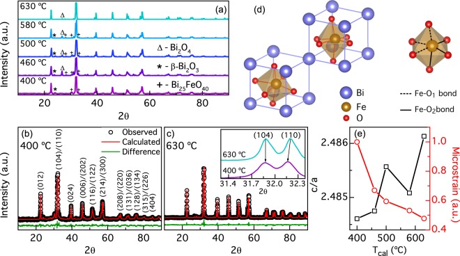
Figure 1(a) shows the XRD pattern for BFO NPs calcined at five different temperatures (Tcal) from 400 °C to 630 °C. In all samples, the peaks coincide with planes expected for BFO. Additional peaks can be attributed to secondary phases formed in the fabrication process. Rietveld refinements of the XRD patterns for nano-powders calcined from 400 °C to 630 °C are shown in Fig. 1(b,c) and Supplementary Fig. S1. Detailed analysis of the refinement is shown in Supplementary Fig. S2 and in Supplementary Table S1. In Fig. 1(b) each peak is labeled with its corresponding Miller indices in hexagonal representation15. The typical double peaks (104)/(110) around from the BFO NPs calcined at 400 °C and 630 °C are shown in the inset of Fig. 1(c). The (110) peak shifts toward lower angles in the sample calcined at a temperature of 400 °C, attributed to an increment of the crystal strain caused by NPs size confinement16. The BFO phase percentage obtained from the refinement was 70.7% and 90.5% for 400 °C and 630 °C, respectively (see Supplementary Fig. S2). The refinements confirm that our NPs have a rhombohedral perovskite structure with an R3c space group symmetry (Chi-square fittings are: and ). Figure 1(d) shows a schematic construction of a BFO unit cell in a pseudocubic system. The perovskite structure, characterized by the octahedral coordination, can be observed. In the NPs calcined at 400 °C, the lattices parameters calculated were a = b = 5.5850 Å, and c = 13.8764 Å; while for the NPs calcined at 630 °C were a = b = 5.5810 Å, and c = 13.8751 Å, which are in close agreement with bulk BFO reports15. Figure 1(e) shows the evolution of the ratio c/a and microstrain vs. Tcal. The microstrain was roughly estimated using the Williamson-Hall equation17,18 without including the correction due to instrumental broadening and normalized to the highest value, with the purpose of seeing the strain evolution trend across the samples. This anticorrelation between c/a ratio and microstrain shows that our NPs exhibits variations in the degree of crystal strain that decreases with Tcal.
Figure 1.
(a) X-ray diffractograms of BFO NPs calcined at different temperatures. Dominant secondary phases Bi2O4, β-Bi2O3 and Bi25FeO40 are indicated with Δ, * and + symbols respectively. Less intense secondary phases ε-Bi2O3 and Bi2Fe4O9 are not indicated but they were also identified and included in diffractograms Rietveld refinements. Rietveld refinements for 400 °C and 630 °C are shown in (b) y (c). Inset: Diffractogram zoom around 2θ ~ 32° for samples calcined at 400 °C and 630 °C showing the reflections of (104) and (110) planes. (110) corresponding peak is shifted to lower angles as NP size decreases, as the arrow indicates. Typical R3c rhombohedral reflections planes for BFO are indicated in (b,d) BFO perovskite unit cell in pseudocubic representation. Octahedral organization of Fe and O ions is showed indicating Fe-O bonds. (e) Lattice parameters (calculated with refinements) ratio c/a and microstrain (roughly estimated without the instrumental broadening) as functions of Tcal indicating increment of strain with NPs size decrease.
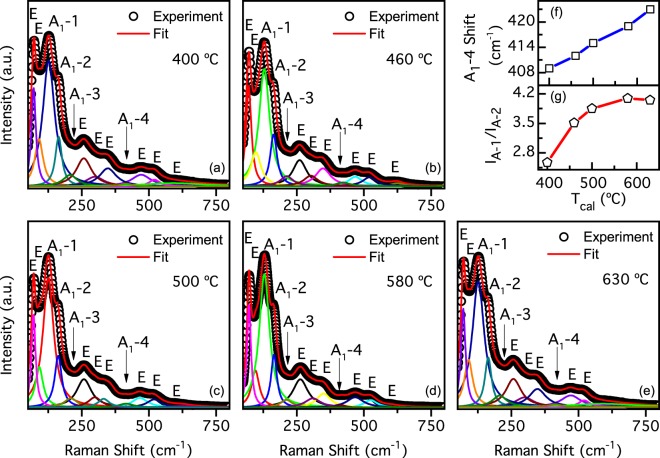
Figure 2 shows the Raman spectra obtained at room temperature for the studied samples. We have identified 12 active modes (4 A1 and 8 E) out of 13 modes present in bulk (4A1 + 9E) in the Raman spectra by a peak-fitting procedure using Lorentzian distributions. Raman spectra of our NPs, for each Tcal, are in good agreement with those expected for rhombohedral BFO with a R3c space group. Therefore, we confirm that our NPs have the ferroelectric R3c phase. Because there are not considerable changes between the Raman spectra, we could infer that ferroelectric phase is present in all samples19,20. However, an unexpected red shift of all A1 peaks from the typical values reported for bulk BFO can be observed. Furthermore, such red shift increases with decreasing Tcal (see Supplementary Table S2) and with respect to BFO bulk single crystal reported Raman shifts20. For example, in the sample calcined at 400 °C, we observe a red shift of 15.6% for the A1 − 1 Raman mode, 8.5% for A1 − 2 while for A1 − 3 and A1 − 4 we observe red shifts of 7.9% and 16.5%, respectively. In Fig. 2(f) we show the A1 − 4 mode red shift evolution as a function of Tcal; such mode is associated to Fe-O1 and Fe-O2 bonds21,22 (see Fig. 1(f)). From these results we can identify a possible distortion of Fe-O bonding distances or Fe-O-Fe bonding angle and relate them with the calcination. Indeed, such red shifts observed in Raman spectra and the analysis of the Williamson-Hall equation from XRD results could be related to the strain of NPs and the size confinement. Similarly, A1 − 1 Raman peak suppression can be associated to an increase of the magnetoelectric coupling in BFO10. In our samples, such suppression increases with decreasing Tcal, as shown in Fig. 2(g) where the A1 − 1 integral intensity IA1 (normalized to the A1 − 2 integral intensity IA2) increase with Tcal.
Figure 2.
Raman spectra of NPs calcined at (a) 400 °C, (b) 460 °C, (c) 500 °C, (d) 580 °C and (e) 630 °C. Symbols represent observed spectra in each figure. Figures also show spectra fitting curves and deconvoluted individual peaks that have been labeled with corresponding indices according to simetry of raman modes expected for the BFO. (f) Red shift of A1 − 4 peak with Tcal increase. (g) A1 − 1 peak integral intensity increase with higher calcination temperature.
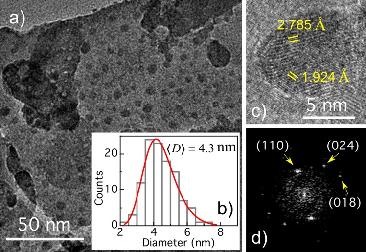
Figure 3(a) shows a TEM image of NPs calcined at 400 °C. Using this image, as well as others from several TEM images, the size distribution presented in Fig. 3(b) was built. The diameter distribution was fitted with a lognormal-type function, from which a mean diameter close to 4.3 nm was determined, as shown in the figure. High resolution TEM image of NP with nearly 10 nm diameter is shown in Fig. 3(c). Interplanar Bragg distances 2.785 Å and 1.924 Å can be identified in the NP, which are in good agreement with the distance between (110) and (024) lattice planes of BFO. From FFT of TEM image (see Fig. 3(d)), a third spot appears, whose interplanar distance of 1.632 Å coincide with that of (018) BFO lattices planes, additionally to (110) and (024) planes observed on high resolution image15. Furthermore, Supplementary Fig. S3 shows the size distribution, for the NPs calcined at 630 °C, extracted from several FE-SEM images like that showed in the inset. From the lognormal-type function fitting we obtain a mean particle diameter close to 54 nm.
Figure 3.
(a) TEM image of BFO NPs calcined at 400 °C. Inset: Histogram of the NPs size distribution obtained from the TEM image. The lognormal fit is also shown. (c) TEM image of a single nanoparticle and (d) corresponding Fourier transform.
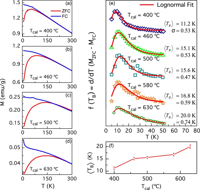
Figure 4 shows the zero-field cooling and field cooling (ZFC-FC) magnetization curves for H = 1 kOe applied field. For all samples, the FC magnetization decreases monotonically, while the ZFC curves reach a maximum (Tmax), which appears at higher temperatures with increasing Tcal. The ZFC curves resemble the ones of magnetic nanoparticles with a superparamagnetic behavior. Thus, the temperature at which the maximum of the ZFC magnetization occurs can be ascribed to a blocking temperature (TB), i.e., this temperature is closer to the one in which the system undergoes a blocking-to-unblocking transition. Upon increasing temperature, the ZFC and FC curves merge few degrees above the maximum reached by the ZFC curve. This point, known as the irreversibility temperature (Ti), can be interpreted as an indicative of the existence of a blocking temperature distribution f(TB), associated to a NP size distribution23,24. We estimated f(TB) in each sample using the reduced-magnetization derivative, calculated as 25. Figure 4(i) shows f(TB) distributions for all samples and it can be noticed that they can be well fitted with a lognormal-type function. The obtained range from 11.2 K for the sample calcined at 400 °C to 20.0 K in sample calcined at 630 °C. The dependence of with Tcal is plotted in Fig. 4(j). An increase of the Néel relaxation time could explain the increment of with Tcal in our NPs. Thus, the blocked-superparamagnetic transition temperature increases with NP size26, and therefore suggests that the NPs have a nearly superparamagnetic behavior.
Figure 4.
(a–d) ZFC-FC magnetization curves of the NPs for H = 1 kOe. (e) Blocking temperature obtained from the derivative method and lognormal fittings for (a–d) ZFC-FC curves. (f) Mean blocking temperature TB as a function of the calcination temperature of the NPs.
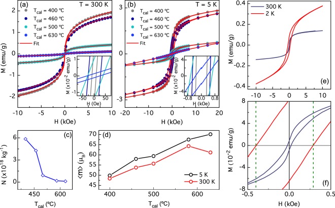
Figure 5(a) shows the isothermal magnetization hysteresis loops (M vs. H) measured at 300 K for the studied BFO NPs. We found a S-shape and almost null values of the coercive field (HC) resembling a near superparamagnetic-like behavior, which confirm that observed at ZFC-FC curves. At higher fields, up to 3 Tesla (not shown), the magnetization does not to reach saturation indicating the existence of a paramagnetic-like component, which is possibly related to those disordered magnetic moments located at the NP surface. The NPs magnetization increases with decreasing Tcal. In contrast, coercive field (HC) drastically increase at low temperatures, as shown in Fig. 5(b) for T = 5 K and can be attributed to a higher contribution from a ferromagnetic order. It can be noticed also that the paramagnetic component is present in all samples.
Figure 5.
(a) Magnetic hysteresis loops taken at room temperature and (b) at 5 K of BFO NPs prepared at different calcination temperatures (Tcal). The red line represents the fit using a Langevin equation. (c) Best fitting-parameters for N (number of NPs per mass unit) and (d) m (particle magnetic moment in Bohr magnetons units) with the calcination temperature for M vs. H experimental curves taken at 300 K and 5 K. (e) M vs H hysteresis at 2 K and 300 K curve for a NPs sample calcined at 600 °C. (f) Hysteresis loop zoom; 2 K curve exhibits exchange bias effect.
We performed fittings of the M vs. H curves using a modified Langevin function (to include a HC dependence) where we take into account a lognormal-type distribution magnetic moments27 as suggested by our TEM and FE-SEM images and magnetic data. At last, we include a linear parameter with the field in the fitting calculations to take into account the paramagnetic contributions. Best fitting results are shown as continuous solid red lines in Fig. 5(a,b). Whit this procedure we were able to obtain the average magnetic moment per NP, , and number of NPs per unit mass, N (see Supplementary Table S3).
From Fig. 5(c) one can infer that N decreases monotonically with Tcal. On other hand, Fig. 5(d) shows the evolution of as function of , at 300 K and 5 K. In both cases, an increase of with Tcal is observed. This means that increase with NP size as opposite to the total magnetization. Such behavior can be understood assuming that at a given NP size, exceeding the long-cycloid spin structure, exhibits an antiferromagnetic core surrounded by a shell of uncompensated spins. Such magnetization-moment anticorrelation can be due to a surface to volume ratio effect10.
Additionally, Fig. 5(e) shows magnetization hysteresis loops at 300 K and 2 K, on BFO NPs calcined at 600 °C. Room temperature hysteresis loop exhibit superparamagnetic-like behavior with a very week ferromagnetic component (as stated before), with a 22 Oe coercive field. Regarding to low temperature hysteresis loop, coercive field increases to 340 Oe and NPs magnetism become predominantly ferromagnetic. Interestingly, a closer inspection of the magnetization, near zero field, shows a horizontal shift, see Fig. 5(f). Such a phenomenon is usually associated with an Exchange Bias (EB) effect, originated from the spins interaction at the interface between ferromagnetic and antiferromagnetic layers28. This effect is observed at low temperatures close 2 K. In our NPs, such effect could be associated with a core-shell structure of NPs with an antiferromagnetic core and a ferromagnetic shell. This effect have been observed in BFO NPs29,30. EB field has been calculated with the left (HC1) and right (HC2) coercive fields as . The hysteresis loop taken at 2 K has a HEB of 56 Oe, while HEB taken at room temperature is zero.
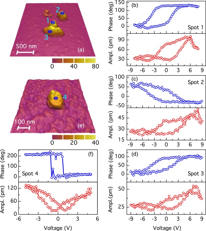
Figure 6(a) shows AFM topography of dispersed BFO NPs calcined at 630 °C on an Au/Ti/SiO2/Si substrate. Such NPs agglomerations have lateral sizes of several hundred nanometers, while thickness ranges from 45 nm to 70 nm, approximately. We have performed local measurements of amplitude and phase piezoelectric hysteresis curves, on marked spots inside the AFM picture employing the switching-spectroscopy PFM method (SS-PFM)14, results are shown in Fig. 6(b,d). Phase hysteresis loops correspond to ferroelectric behavior with coercive fields between 2.55 V and 2.65 V. The small difference in values of the coercive fields can relate to the NP size or to the direction polar vector for switching. Interestingly the polarization phase switching is near to 140° and approximately to 109° and 71° in Fig. 6(d,e), respectively. Such values are consistent with the values predicted by the switching phase mechanism expected for rhombohedral BFO7. We calculate the area of the phase-voltage hysteresis loops14, for spots 1 to 3 and obtained the respective values 764.8 a.u., 548.9 a.u., and 499.4 a.u. corresponding to NPs of 70 nm, 50 nm and 45 nm sizes. It can be noted that the area mostly decreases with the NP size. The corresponding piezoelectric amplitude hysteresis for each spot, taken simultaneously, show typical butterfly shape loops corroborating the ferroelectric properties of BFO NPs. From these we calculated the local longitudinal piezoelectric coefficient d33 for spots 1, 2 and 3, the respective values are nearly to 7.74 pmV−1, 2.48 pmV−1 and 2.16 pmV−1. Thus, d33 coefficient mostly decrease with the NPs size similar to the switching area. The above results suggest that the ferroelectric switching can be tuned with the NP size. In addition, Fig. 6(e,f) shows the AFM topography and local PFM piezoelectric hysteresis loops of NPs calcined at 600 °C and dispersed on a Ag/Ti/SiO2/Si substrate. Piezoelectric curves were taken on the spot 4 marked on the topography image of the NP with size close to 25 nm. Phase hysteresis loop have a coercive field close to 1.5 V and a phase switching near to 180 °C corresponding to a ferroelectric behavior. Regarding to the amplitude piezoelectric hysteresis loop, this local measurement exhibits a typical and well-shaped butterfly. Calculating the coefficient d33 we obtain a value near to 13.6 pmV−1. This can be observed a change in the coercive fields as well as d33 coefficient regarding to the calcined at 630 °C sample results. The probable cause of such behavior is the change of bottom electrode from Au to Ag, changing with this the depletion layer at the electrode-NP interface and thus the measured piezoelectric properties31.
Figure 6.
(a) AFM topography image of BFO NPs calcined at 630 °C. Spots on which hysteresis PFM curves were measured are shown. Curves (b–d) are the phase (blue) and amplitude (red) ferroelectric hysteresis loops corresponding to spots 1 to 3 on BFO nanoparticles, respectively. (e) AFM topography image of nearly 25 nm BFO NP calcined at 600 °C. On marked spot was measured (f) phase and (g) amplitude piezoelectric hysteresis loops.
Summary
In summary, we successfully synthesized BFO nanoparticles using the sol-gel method. Structural characterization suggests NPs have a distorted rhombohedral crystal lattice due to strain effects. The strain increases with decreasing calcination temperature, suggesting smaller particles have stronger strain. The NPs have been observed to be magnetically polarizable and that its magnetization increases with decreasing particle size. At low temperatures, the NPs show ferromagnetic order; at room temperature, they show a closer superparamagnetic-like behavior. Furthermore, the blocked-superparamagnetic transition, related to the observed blocking temperatures, suggests that this evolution take place at larger temperatures as NPs size increases. We have observed in the 600 °C sample, a slight shift of the hysteresis loops at 2 K, suggesting a small exchange bias effect. A possible scenario can be an antiferromagnetic-ferromagnetic coupling in a core-shell structure. Finally, we have corroborated that NPs are ferroelectric through piezoelectric hysteresis loops measurement on individual NPs and found that d33 coefficient increases with NP size as well as the total switching area. Our results allowed us to conclude that the BFO nanoparticles are multiferroic, i.e. ferroelectric and ferromagnetic, in contrast to its bulk behavior, where the magnetic coupling is known to be antiferromagnetic. These results open an avenue to control the multiferroicity order using strain resulting from the NPs confinement.
Supplementary information
Acknowledgements
This work started at the Nanomagnetism Laboratory at Universidad de los Andes. We thank Prof. Ivan K. Schuller for useful discussions and for allowing preliminary measurements at University of California San Diego. We acknowledge support from FAPA program by means of Facultad de Ciencias and Vicerrectoria de Investigaciones of Universidad de los Andes, Bogotá, Colombia. Funds were also provided by bilateral grant “Tec de Monterrey- Uniandes Program” and Interdisciplinary grant. The authors acknowledge the Brazilian Nanotechnology National Laboratory (LNNano) for the use of electron microscopy facility under the projects # 22424. D.M., O.M.L and M.K. acknowledge the Brazilian agencies FAPESP (2014/26672) and CNPq. We acknowledge the Centro de microscopía de la Universidad de los Andes for the use of FE-SEM. A.C.R acknowledge support from Facultad de Ciencias, Universida de los Andes (2017-II).
Author Contributions
J.G.R. generated the idea. A.C.R. developed the method for the fabrication of BFO NPs. A.C.R. and D.C.-C. fabricated the NPs used in this work. A.C.R. and D.C.-C. performed the first magnetic characterization at Universidad de los Andes. O.M. and M.K. performed SQUID magnetometry measurements and suggested the fitting analysis. J.N, A.C.R. and D.C.-C. performed the PFM measurements. D.M. performed the TEM measurements. D.M. and D.C.-C. did the TEM analysis. A.C.R. and D.C.-C. performed the FE-SEM measurements. D.C.-C. and J.G.R. wrote the first version of the manuscript. All authors discussed the results and worked on the final version of the manuscript.
Data Availability
The data that support the findings of this study are available from the corresponding author upon request.
Competing Interests
The authors declare no competing interests.
Footnotes
Publisher’s note: Springer Nature remains neutral with regard to jurisdictional claims in published maps and institutional affiliations.
Electronic supplementary material
Supplementary information accompanies this paper at 10.1038/s41598-019-39517-3.
References
- 1.Fuentes-Cobas, L. E., Matutes-Aquino, J. A. & Fuentes-Montero, M. E. Magnetoelectricity. In Handbook of magnetic materials 129–229, 10.1016/B978-0-444-53780-5.00003-X (2011)
- 2.Sarkar A, Khan GG, Chaudhuri A, Das A, Mandal K. Multifunctional BiFeO3/TiO2 nano-heterostructure: Photo-ferroelectricity, rectifying transport, and nonvolatile resistive switching property. Appl. Phys. Lett. 2016;108:033112. doi: 10.1063/1.4940118. [DOI] [Google Scholar]
- 3.Hong S, et al. Large Resistive Switching in Ferroelectric BiFeO3 Nano-Island Based Switchable Diodes. Adv. Mater. 2013;25:2339–2343. doi: 10.1002/adma.201204839. [DOI] [PubMed] [Google Scholar]
- 4.Allibe J, et al. Room temperature electrical manipulation of giant magnetoresistance in spin valves exchange-biased with BiFeO3. Nano Lett. 2012;12:1141–5. doi: 10.1021/nl202537y. [DOI] [PubMed] [Google Scholar]
- 5.Zhang JT, et al. Origin of magnetic anisotropy and spiral spin order in multiferroic BiFeO3. Appl. Phys. Lett. 2012;100:242413. doi: 10.1063/1.4729555. [DOI] [Google Scholar]
- 6.Park J-G, Le MD, Jeong J, Lee S. Structure and spin dynamics of multiferroic BiFeO3. J. Phys. Condens. Matter. 2014;26:433202. doi: 10.1088/0953-8984/26/43/433202. [DOI] [PubMed] [Google Scholar]
- 7.Kubel F, Schmid H. Structure of a ferroelectric and ferroelastic monodomain crystal of the perovskite BiFeO3. Acta Crystallogr. Sect. B Struct. Sci. 1990;46:698–702. doi: 10.1107/S0108768190006887. [DOI] [Google Scholar]
- 8.Sosnowska I, Zvezdin AK. Origin of the long period magnetic ordering in BiFeO3. J. Magn. Magn. Mater. 1995;140–144:167–168. doi: 10.1016/0304-8853(94)01120-6. [DOI] [Google Scholar]
- 9.Tabares-Mun̄oz C, Rivera J-P, Bezinges A, Monnier A, Schmid H. Measurement of the Quadratic Magnetoelectric Effect on Single Crystalline BiFeO3. Jpn. J. Appl. Phys. 1985;24:1051. doi: 10.7567/JJAPS.24S2.1051. [DOI] [Google Scholar]
- 10.Park T-J, Papaefthymiou GC, Viescas AJ, Moodenbaugh AR, Wong SS. Size-Dependent Magnetic Properties of Single-Crystalline Multiferroic BiFeO3 Nanoparticles. Nano Lett. 2007;7:766–772. doi: 10.1021/nl063039w. [DOI] [PubMed] [Google Scholar]
- 11.Huang F, et al. Peculiar magnetism of BiFeO3 nanoparticles with size approaching the period of the spiral spin structure. Sci. Rep. 2013;3:2907. doi: 10.1038/srep02907. [DOI] [PMC free article] [PubMed] [Google Scholar]
- 12.Hasan M, Islam MF, Mahbub R, Hossain MS, Hakim MA. A soft chemical route to the synthesis of BiFeO3 nanoparticles with enhanced magnetization. Mater. Res. Bull. 2016;73:179–186. doi: 10.1016/j.materresbull.2015.09.007. [DOI] [Google Scholar]
- 13.Doebelin N, Kleeberg R. Profex : a graphical user interface for the Rietveld refinement program BGMN. J. Appl. Crystallogr. 2015;48:1573–1580. doi: 10.1107/S1600576715014685. [DOI] [PMC free article] [PubMed] [Google Scholar]
- 14.Jesse S, Baddorf AP, Kalinin SV. Switching spectroscopy piezoresponse force microscopy of ferroelectric materials. Appl. Phys. Lett. 2006;88:062908. doi: 10.1063/1.2172216. [DOI] [PubMed] [Google Scholar]
- 15.Palewicz A, Przeniosło R, Sosnowska I, Hewat AW. Atomic displacements in BiFeO3 as a function of temperature: neutron diffraction study. Acta Crystallogr. Sect. B Struct. Sci. 2007;63:537–544. doi: 10.1107/S0108768107023956. [DOI] [PubMed] [Google Scholar]
- 16.Zhang, C. et al. Room temperature exchange bias in multiferroic BiFeO3 nano- and microcrystals with antiferromagnetic core and two-dimensional diluted antiferromagnetic shell. J. Nanoparticle Res. 19 (2017).
- 17.Mocherla PSV, Karthik C, Ubic R, Ramachandra Rao MS, Sudakar C. Effect of microstrain on the magnetic properties of BiFeO3 nanoparticles. Appl. Phys. Lett. 2014;105:132409. doi: 10.1063/1.4897143. [DOI] [Google Scholar]
- 18.Mote V, Purushotham Y, Dole B. Williamson-Hall analysis in estimation of lattice strain in nanometer-sized ZnO particles. J. Theor. Appl. Phys. 2012;6:6. doi: 10.1186/2251-7235-6-6. [DOI] [Google Scholar]
- 19.Haumont R, Kreisel J, Bouvier P, Hippert F. Phonon anomalies and the ferroelectric phase transition in multiferroic BiFeO3. Phys. Rev. B. 2006;73:132101. doi: 10.1103/PhysRevB.73.132101. [DOI] [Google Scholar]
- 20.Fukumura H, et al. Observation of phonons in multiferroic BiFeO3 single crystals by Raman scattering. J. Phys. Condens. Matter. 2007;19:365224. doi: 10.1088/0953-8984/19/36/365224. [DOI] [PubMed] [Google Scholar]
- 21.Chen P, et al. Size-Dependent Infrared Phonon Modes and Ferroelectric Phase Transition in BiFeO3 Nanoparticles. Nano Lett. 2010;10:4526–4532. doi: 10.1021/nl102470f. [DOI] [PubMed] [Google Scholar]
- 22.Chaturvedi S, Das R, Poddar P, Kulkarni S. Tunable band gap and coercivity of bismuth ferrite–polyaniline core–shell nanoparticles: the role of shell thickness. RSC Adv. 2015;5:23563–23568. doi: 10.1039/C5RA00933B. [DOI] [Google Scholar]
- 23.Guduri BR, Luyt AS. Structure and Mechanical Properties of Polycarbonate Modified Clay Nanocomposites. J. Nanosci. Nanotechnol. 2008;8:1880–1885. doi: 10.1166/jnn.2008.017. [DOI] [PubMed] [Google Scholar]
- 24.Moscoso-Londoño O, et al. Different approaches to analyze the dipolar interaction effects on diluted and concentrated granular superparamagnetic systems. J. Magn. Magn. Mater. 2017;428:105–118. doi: 10.1016/j.jmmm.2016.12.019. [DOI] [Google Scholar]
- 25.Bruvera IJ, Mendoza Zélis P, Pilar Calatayud M, Goya GF, Sánchez FH. Determination of the blocking temperature of magnetic nanoparticles: The good, the bad, and the ugly. J. Appl. Phys. 2015;118:184304. doi: 10.1063/1.4935484. [DOI] [Google Scholar]
- 26.Dormann JL, Fiorani D, Tronc E. Magnetic Relaxation in Fine-Particle Systems. in. Advances in Chemical Physics. 2007;98:283–494. [Google Scholar]
- 27.Mendoza Zélis P, et al. Magnetic properties study of iron-oxide nanoparticles/PVA ferrogels with potential biomedical applications. J. Nanoparticle Res. 2013;15:1613. doi: 10.1007/s11051-013-1613-6. [DOI] [Google Scholar]
- 28.Nogués J, Schuller IK. Exchange bias. J. Magn. Magn. Mater. 1999;192:203–232. doi: 10.1016/S0304-8853(98)00266-2. [DOI] [Google Scholar]
- 29.Huang F, et al. The exchange bias behavior of BiFeO3 nanoparticles with natural core-shell structure. Sci. Rep. 2018;8:2311. doi: 10.1038/s41598-018-19676-5. [DOI] [PMC free article] [PubMed] [Google Scholar]
- 30.Wu H, Xia W, Zhu X. Synthesis of single-crystalline BiFeO3 nanoparticles and their magnetic properties. Ferroelectrics. 2017;519:1–8. doi: 10.1080/00150193.2017.1362276. [DOI] [Google Scholar]
- 31.Chen L, et al. Electrical and mechanical switching of ferroelectric polarization in the 70 nm BiFeO3 film. Sci. Rep. 2016;6:19092. doi: 10.1038/srep19092. [DOI] [PMC free article] [PubMed] [Google Scholar]
Associated Data
This section collects any data citations, data availability statements, or supplementary materials included in this article.
Supplementary Materials
Data Availability Statement
The data that support the findings of this study are available from the corresponding author upon request.


