Abstract
Development of a three-dimensional (3D) vascular co-cultivation system is one of the major challenges to provide an advanced analytical platform for studying blood vessel related diseases. To date, however, the in vivo-like vessel system has not been fully realized due to the difficulty of co-cultivation of the cells with orthogonal alignment. In this study, we report the utilization of microfabrication technology to construct biomimetic 3D co-cultured vasculature. First, microwrinkle patterns whose direction was perpendicular to the axis of a circular microfluidic channel were fabricated, and vascular smooth muscle cells (VSMCs) were cultured inside the microchannel, leading to an in vivo-like circumferential VSMC layer. Then, human umbilical vein endothelial cells (HUVECs) were co-cultured on the circumferentially aligned VSMC, and the success of double layer formation of HUVEC-VSMC in the circular microchannel could be monitored. After HUVEC cultivation, we applied shear flow in order to induce the orientation of HUVEC parallel to the axis, and the analysis of orientation angle and spreading area of HUVECs indicated that they were changed by shear stress to be aligned to the direction of flow. Thus, the HUVEC and VSMC layer could be aligned with a distinct direction. The expression level of VE-Cadherin located at the boundary of HUVECs implies in vivo-like vascular behavior. The proposed in vitro microfluidic vascular assay platform would be valuable for studying vascular diseases with high reliability due to in vivo-likeness.
I. INTRODUCTION
Preclinical screening methods for candidate drugs mainly rely on animal models or primary cell lines cultured in a plastic flask.1 In vivo animal tests require high cost and prolonged time, while in vitro cell line test suffers from data fidelity due to huge differences between in vivo and in vitro experimental environments.2 To bridge such a gap, the construction of the in vivo-like in vitro bioassay platform is of great importance, which will not only save cost and time to search for the lead identification among drug candidate libraries, but also improve data reliability to reduce failure rate in the clinical trial. To this end, a biomimetic organ-on-a chip has been recently pursued. For example, an artificial blood vessel system has been explored for understanding fundamental biology of the blood vessel as well as providing a vascular disease model such as thrombosis.3–5 The interior structure of in vivo vasculature is composed of a monolayer of endothelial cells (ECs) as an inner part and smooth muscle cell (SMC) media that surround the EC layer. Since the alignment of ECs and SMCs is orthogonal, such a co-cultivation with a unique cellular direction in a circular channel remains a challenge. In the past, various in vitro vascular co-cultivation systems using ECs and SMCs have been proposed. However, most of them were conducted on the two-dimensional static platforms,6–8 which were still far from the in vivo vascular structure.
Recent advancement of microfluidic technology has allowed us to culture the cells three-dimensionally (3D) and exert shear force on the cells by circulating the cell culture media.9 In the early stage of developing the in vitro blood vessel in the microfluidics, the cross-sectional shape of the microchannels was restricted to square, even though in vivo EC layer is formed in the circular intima. However, the microfluidic channels with square cross section have been still widely used due to the ease of fabrication processes.10–12 Since the flow rate and shear stress are quite different between circular and square microfluidic channels, the circular microchannel should be utilized to mimic in vivo-like vasculature. Several reports have shown the fabrication of the circular microfluidic channels for preparing in vitro vascular networks, but their cultivation in the circular microchannel was confined to only ECs.13 In the case of the SMCs, they are oriented and elongated circumferentially in the real blood vessel. That is why the construction of 3D in vivo-like SMC is difficult. Since the architecture of SMCs has a heavy impact on the vascular functions,14,15 it is important to realize the circumferentially aligned SMCs with contractile morphology in the circular microfluidic channel. Although Yoshida et al. showed the multilayered vascular cell networks in the circular hydrogel,16 they ignored the cellular alignment of ECs and SMCs, and their shape and morphology, which are crucial for vascular functions.
In this study, we proposed the microfluidic approaches to mimic the in vivo-like vascular system using EC and SMC co-cultivation with a distinct pattern. Following the circumferential alignment of SMCs in a circular microchannel by using microwrinkles, we further expended the 3D vascular co-cultivation with primary vascular smooth muscle cells (VSMCs) and human umbilical vein endothelial cells (HUVECs) in the circular microfluidic channels to realize the artificial blood microsystem.17 The alignment of VSMCs perpendicular to the axis of the microchannel, the co-cultivation of HUVECs parallel to the axis of the microchannel, and shear stress induced cell reorganization were investigated together with cellular morphology changes.
II. EXPERIMENTAL
A. Materials
Primary vascular smooth muscle cells (VSMCs) and human umbilical vein endothelial cells (HUVECs) were obtained from Lonza (MD, USA). SmBM (smooth muscle cell basal medium), SmGM SingleQuots (supplements and growth factors), EBM-2 (endothelial cell basal medium), and EGM-2 SingleQuots (supplements and growth factors) were also supplied from Lonza (MD, USA). Poly-d-lysine (PDL), Hexamethyldisilazane (HMDS), 10% neutral buffered formalin, Triton X-100, bovine serum albumin (BSA), and 4′,6-diamidino-2-phenylindole (DAPI) were purchased from Sigma Aldrich (MO, USA). Anti-Human CD144 (VE-Cadherin) Alexa Fluor 488 and Alexa Fluor 488 phalloidin were ordered from eBioscience (CA, USA) and Invitrogen (USA), respectively. A Polydimethylsiloxane (PDMS) prepolymer and a curing agent were obtained from Dow Corning Corporation (Sylgard 184 elastomer kit, USA).
B. Fabrication of a circular microfluidic channel with circumferential microwrinkle patterns
A concave half-circular microchannel was fabricated on a polycarbonate (PC) sheet by a computer numerical control (CNC) machine. A PDMS prepolymer and its curing agent were mixed at a weight ratio of 10:1 and poured on the patterned PC sheet. After degassing, the PDMS mixture was cured in an oven at 80 °C overnight. The cured PDMS sheet was peeled off from the PC sheet, so the convex half-circular micropattern was produced on the PDMS sheet. The convex half-circular micropattern was used as a master mold for generating concave half-circular PDMS microchannels. After treatment of HMDS on the convex half-circular micropatterned PDMS for 1 h, the mixture of the PDMS prepolymer and curing agent was poured, degassed, and cured in an oven at 80 °C overnight. Owing to the HMDS treatment, the top PDMS sheet could be detached, which contained concave half-circular microchannels.
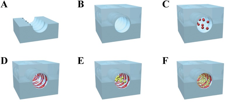
Circumferential microwrinkles were patterned inside the concave half-circular microchannel following the previous report.17 Briefly, a concave half-circular PDMS sheet was clamped and uniaxially stretched to 140% in length by a custom-made apparatus. The surface was exposed to UV/O in a UV chamber (Ahtech LTS CO., Ltd, Korea) for 60 min, and then the PDMS sheet was released to recover its original length. The intensity of UV light was fixed at 28 mW/cm2, and the distance between a UV lamp and the PDMS sheet was 1 cm. Due to the difference of modulus between the PDMS and the formed oxide layer, circumferential microwrinkle patterns were produced on the curvature surface of the UV-treated PDMS sheet as shown in Fig. 1(a).17 A couple of the half-circular microwrinkle patterned microchannels were treated by O2 plasma, carefully aligned and permanently bonded together to form the circular microchannel [Fig. 1(b)].
FIG. 1.
Overall procedure for producing the in vivo like vasculature. (a) and (b) The microwrinkle patterned circular microchannel was first fabricated, and [(c) and (d)] the VSMCs were circumferentially aligned along the microwrinkles. (e) and (f) Then, HUVECs were cultured on the VSMCs and reoriented toward the flow direction by shear stress.
C. Co-cultivation of VSMCs and HUVECs in the circular PDMS microchannels
VSMCs of passage numbers 2–7 were cultured in a complete media containing SmBM and SmGM SingleQuots. The cells were grown in a humidified 5% CO2 incubator at 37 °C. After confluence, the cells were trypsinized with 0.25% trypsin and 0.05% EDTA (Gibco, Invitrogen, USA) for 3 min and then concentrated by centrifugation. The cells were resuspended with a complete medium to adjust the cell concentration to 1 × 10⁵ cells/ml. For the VSMC cultivation inside the circular PDMS channel, the surface of the circular microchannel was filled with 1 mg/ml PDL at room temperature (RT) for 30 min, removed, and dried. Then, 1 mg/ml fibronectin was coated on the PDL layer at RT for 2 h. After washing with distilled water, the VSMC seeding was carried out by loading a cell solution (2.5 × 10⁵ cells/ml) into the microchannel [Fig. 1(c)]. Once the cells were adherent on the bottom surface after 40 min incubation, the microdevice was turned upside down to attach the cells on the top surface. The VSMC seeding (2.5 × 10⁵ cells/ml) was repeated into the microchannel to fully cover the circular microchannel with the VSMCs [Fig. 1(d)]. Then, the complete medium was added in the microchannel to proliferate the VSMCs for 1 day.
For HUVEC cultivation on the VSMC layer, HUVECs of passage numbers 2–5 were cultured in a complete media containing EBM-2 and EGM-2 SingleQuots. The cells were grown in a humidified 5% CO2 incubator at 37 °C. After confluence, the cells were trypsinized with 0.25% trypsin and 0.05% EDTA for 3 min and then concentrated by centrifugation. The cells were resuspended with a complete medium to adjust the cell concentration to 1 × 10⁶ cells/ml. The stock solution of HUVEC was injected into the microchannel where the VSMCs were aligned along the microwrinkles [Fig. 1(e)]. Similar to the procedure of VSMC, the microchannel was turned upside down after 40 min incubation in a humidified incubator at 37 °C, and the second seeding of the HUVEC with a cell density of 1 × 10⁶ cells/ml was conducted for entire cell adhesion inside the circular microchannel [Fig. 1(f)]. After confirmation of endothelial cell attachment, a co-cultivation medium (mixture of the VSMC and HUVEC medium with a volume ratio of 5:5) was supplied at a flow rate of 0, 100, and 300 μl/h for 24 h using a syringe pump (Sercrim Lab Tech., Korea) to monitor the morphology change of HUVECs.
D. Immunofluorescence staining and imaging
The process of 3D co-cultivation in the circular microchannel was monitored by a fluorescence microscope (Nikon, ECLIPSE, TE 2000-U, Japan), and all fluorescence staining images were obtained by a confocal laser microscope (Nikon, D-ECLIPSE, C1si, Japan). For filamentous actin or VE-cadherin staining, the treatment of a 10% neutral buffered formalin solution for 10 min, 0.1% Triton X-100 for 5 min, and a 0.1% BAS solution for 5 min was serially performed. For staining filamentous actin, an Alexa Fluor 488 phalloidin solution was injected into the microchannel and incubated for 20 min. In the case of the VE-cadherin staining, Anti-Human CD144 (VE-cadherin) Alexa Fluor 488 was injected and incubated for 40 min. After that, a DAPI solution was finally injected for nuclear staining for 30 min. A washing step was executed with Phosphate-buffered saline (PBS) twice when the reagents were changed.
The 3D images of the co-cultured VSMCs and HUVECs in the circular microchannel were recorded by the z-stack (1 μm spacing) method. The orientation angle was defined as the angle from the axis of the microchannel to the major axis of cells, ranging from 0° (a cell aligned parallel to the axis of the microchannel) to 90° (a cell perfectly aligned perpendicular to the axis of the microchannel). The spreading area of HUVECs was measured by setting the boundary of each cell. More than 30 individual cells were analyzed for statistically evaluating orientation angles and spreading areas of the cells.
III. RESULTS
A. Optimization of the concentration of a VSMC solution to fully cover the circular microfluidic channel
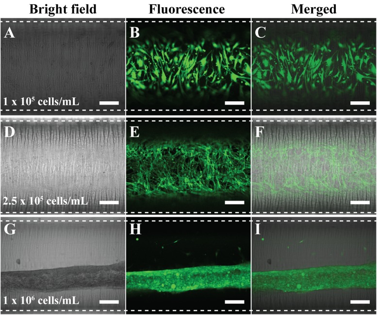
The first step is to cultivate the circumferential VSMC along the microwrinkle pattern. To fully cover the surface of the circular microchannel, it was necessary to optimize the cell concentration. Using the microchannel whose dimension was 30 mm in length × 1 mm in diameter (∼23 μl volume), we seeded the cell solution with different concentrations (1 × 10⁵, 2.5 × 10⁵, and 1 × 10⁶ cells/ml) and cultured for 1 day. Then, the cell coverage was investigated by green fluorescence staining of filamentous actin. In the case of 1 × 10⁵ cells/ml concentration, the VSMCs could not cover the whole surface of the microfluidic channel and they were not connected. Thus, many empty spaces between the cells were observed [Figs. 2(a)–2(c)]. The use of 2.5 × 10⁵ cells/ml concentration resulted in the full extension and coverage in the circular microfluidic channel. Moreover, the VSMCs were aligned along with the microwrinkle direction. They formed spindle and elongated morphology and the three-dimensional in vivo-like alignments with cell-cell interaction [Figs. 2(d)–2(f)]. In the real blood vessel, the VSMC media consist of multiple cell layers, while the HUVECs are formed as a monolayer in the intima. Thus, in order to mimic the real VSMC media, multiple cell stacking was necessary. When 1 × 10⁶ cells/ml concentration was used, the VSMCs, however, were turned into fiber-like shapes after 1-day cultivation. Instead of spreading out along the microwrinkle pattern, the VSMCs tended to be aggregated and rolled-up at high cell density and sank on the bottom of the channel [Figs. 2(g)–2(i)].
FIG. 2.
Optimized concentration of VSMC to fully cover inside the circular microfluidic channel. The used concentration was [(a)–(c)] 1 × 10⁵ cells/ml, [(d)–(f)] 2.5 × 10⁵ cells/ml, and [(g)–(i)] 1 × 10⁶ cells/ml. Filamentous actin of VSMCs was stained with a green fluorescence dye to be visualized. Dotted lines were the boundaries of the microfluidic channel. Scale bar: 200 μm.
B. Co-cultivation of HUVEC on the VSMC layer in the circular microfluidic channel
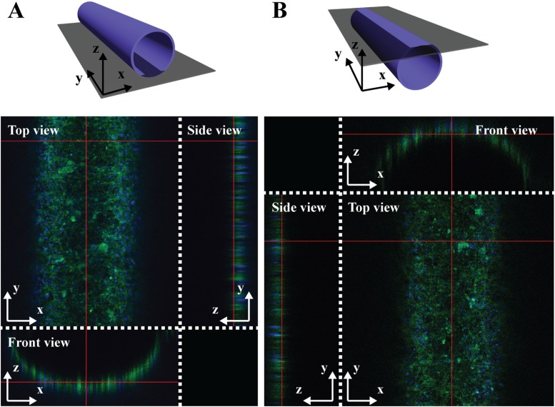
After 3D cultivation of VSMCs with the circumferential alignment inside the circular microchannel, HUVECs were co-cultured on the aligned VSMC layer. To ensure the 3D co-cultivation of the VSMCs and HUVECs in the microfluidic channel, filamentous actin and nuclei of co-cultured vascular cells were simultaneously stained with Alexa Fluor 488 phalloidin (green) and DAPI (blue), and the z-stack images were obtained by using a confocal microscope. Figures 3(a) and 3(b) show the fluorescence images of the top and bottom half-circular channel from different angles (top, side, and front views), demonstrating that the co-cultured VSMC and HUVEC layers were uniformly formed as a hollow tube structure.
FIG. 3.
Top, side, and front views of 3D z-stack images of 3D co-cultured VSMCs and HUVECs in the circular microfluidic channel. (a) A bottom half-circular channel and (b) a top half-circular channel were displayed by staining filamentous actin (green) and nuclei (blue) with Alexa Fluor 488 phalloidin and DAPI, respectively.
C. Effect of shear flow on the alignment and spreading area of HUVECs cultured on the VSMC layer
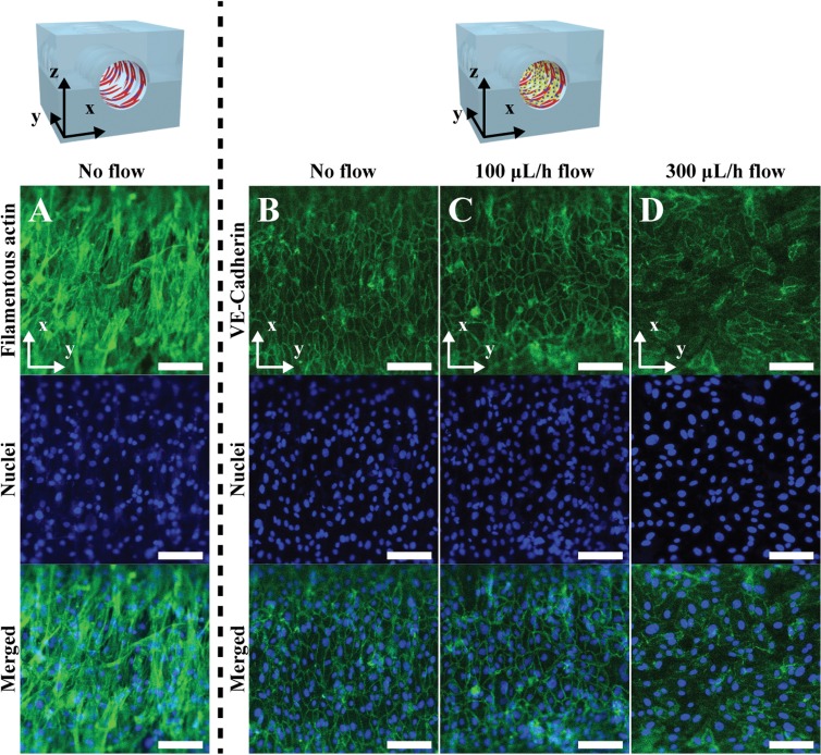
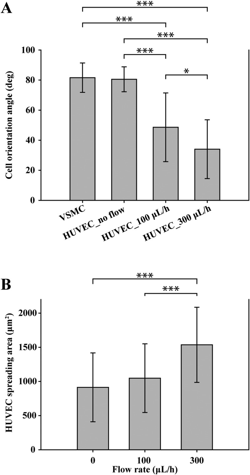
Shear flow in the real blood vessel system plays an important role in causing vascular diseases such as atherosclerosis and aneurysms as well as impeding atherogenesis, thrombosis, and HUVEC apoptosis.18,19 Since the alignment direction and morphology of HUVECs in the real blood vessel system are affected by the flow of blood, we applied shear stress on the co-cultured HUVEC layer to induce the cellular alignment direction parallel to the axis of the microchannel. Figure 4(a) shows the VSMC layer, which was aligned perpendicular to the axis of the microfluidic channel due to the microwrinkle patterns. The stretched direction of filamentous actin (green) of VSMCs was close to that of the microwrinkles, and the average orientation angle was about 81° [Fig. 5(a)]. Moreover, the 3D spindle and elongated morphology was observed, which was a typical contractile phenotype of the native VSMC layer.17,20–22 After 1-day cultivation of VSMCs, HUVECs were co-cultured on the aligned VSMC layer and were stained with Anti-Human CD144 Alexa Fluor 488, which is bound to VE-cadherin located at the boundaries of endothelial cells. Initially, the co-cultured HUVECs were oriented along with the aligned VSMC layer as shown in Fig. 4(b). The average orientation angle was about 80°, which means that HUVECs were parallel to the aligned VSMCs. It seems that the aligned VSMCs due to the microwrinkles served as a guide for patterning HUVECs. In order to mimic the real HUVEC layer of the in vivo blood vessels, it is necessary to switch the alignment direction of HUVECs to that of the axis of the microchannel. To this end, we investigated the effect of shear flow on controlling the orientation angles of HUVECs. Under the dynamic condition at a flow rate of 100 μl/h, the orientation angles of HUVECs were changed to 48°. Although the angle was reduced from 80° to 48°, its value implies that HUVECs were still randomly distributed [Fig. 4(c)]. If the flow rate increased to 300 μl/h, the orientation angle of HUVECs decreased to 33°. These results strongly suggest that higher flow rate can guide HUVECs to be aligned along with the flow direction. However, the expression level of the VE-cadherin at the junctions of HUVECs at 300 μl/h flow rate was lower than that of a flow rate of 100 μl/h [Figs. 4(c) and 4(d)].
FIG. 4.
The expression of VE-Cadherin of the HUVECs co-cultured on the aligned VSMC layers with a different flow rate. (a) Fluorescence images of the filamentous actin and nuclei of circumferentially aligned VSMCs on the microwrinkled fluidic channel. Fluorescence images of the VE-cadherin and nuclei of the HUVECs co-cultured on the aligned VSMC layers with a flow rate of (b) 0 μl/h, (c) 100 μl/h, and (d) 300 μl/h. Scale bar: 100 μm.
FIG. 5.
The effects of shear flow on the orientation angle and spreading areas of co-cultured HUVECs. (a) Analysis of orientation angles of the VSMCs and the co-cultured HUVECs with respect to the shear flow. (b) Spreading areas of co-cultured HUVECs depending on shear flow. All error bars were measured by a standard deviation of means with n = 30. ***P < 0.0001, *P < 0.05; data were analyzed by the one-way ANOVA with a Tukey post-test.
Figure 5 displays the statistical analysis of the orientation angle and the spreading area of the co-cultured HUVECs on the VSMC layer depending on the flow rate. Figure 5(a) shows that the orientation angle was gradually reduced as the flow rate increased, suggesting that the HUVECs were reoriented toward the flow direction. During this transition, the cell shape became plump, leading to the augmented spreading area (from 913 μm2 without flow to 1536 μm2 with a flow rate of 300 μl/h), but the cell-cell connection was diminished [Fig. 5(b)].
D. Cultivation of HUVEC without the VSMC layer as a control experiment
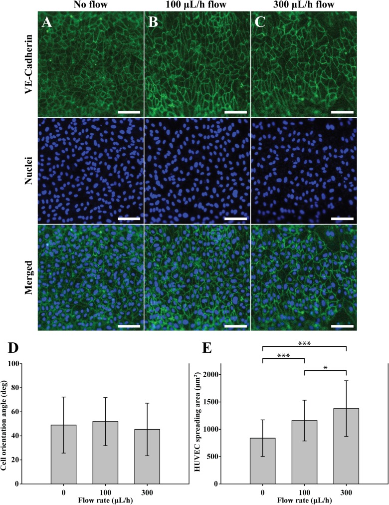
To investigate the role of the VSMCs in forming HUVECs, we performed a control experiment in which HUVECs were cultured on the circular microfluidic channel. The used circular microchannel does not include the microwrinkle patterns and the VSMC layer. Following the same procedure as above, only HUVECs were cultured on the circular microchannel and stained with Anti-Human CD144 Alexa Fluor 488 for imaging VE-cadherin and DAPI for visualizing nuclei. After 1 day, the HUVECs were randomly located with an average orientation angle of 48° probably due to the lack of the aligned VSMC layer. Even under the shear flow conditions, the change of the orientation angle was insignificant as shown in Fig. 6(d). However, the expression of VE-cadherin in the boundary of HUVECs at the flow rate of 300 μl/h [Fig. 6(c)] was clearer than that of the HUVECs co-cultured on the VSMCs [Fig. 4(d)]. The trend of the spreading area of the HUVECs with respect to the shear flow [Fig. 6(e)] was similar to that of co-cultured HUVECs [Fig. 5(b)]. The spreading area of HUVEC was increased from 837 μm2 without flow to 1158 μm2 at 100 μl/h to 1378 μm2 at 300 μl/h, respectively.
FIG. 6.
The effects of shear flow on the orientation angle and spreading areas of the solely cultured HUVECs. Fluorescent images of the solely cultured HUVECs on the non-wrinkled microfluidic channel with a flow rate of (a) 0 μl/h, (b) 100 μl/h, and (c) 300 μl/h. Adherent junctions of the HUVECs were stained with Anti-Human CD144 Alexa Fluor 488 (green). Nuclei were stained with DAPI (blue). Scale bar: 100 μm. Analysis of (d) the orientation angles and (e) the HUVEC spreading areas depending on the flow rate. All error bars were measured by a standard deviation of means with n = 30. ***P < 0.0001, *P < 0.05; data were analyzed by the one-way ANOVA with a Tukey post-test.
IV. DISCUSSION
We have investigated the construction of in vivo-like 3D vascular morphology through microfluidic technology. To our knowledge, this is the first report describing co-cultivation in which vascular cells such as VSMCs and HUVECs are orthogonally aligned. Considering that the structure of VSMCs heavily influences the vascular functions, it is important to realize the in vivo-like 3D morphology. The combination of microwrinkle structures and shear flow in microfluidics can make it possible to create the circumferential alignment of VSMCs and the parallel alignment of HUVECs to the direction of microfluidic channel. We previously carried out an in-depth study on the fabrication of the wrinkle structure and its effect on the cell alignment, and the wrinkle dimension with 30 μm in wavelength and 3 μm in amplitude was selected in this study.17,23
To construct the 3D vascular formation, cell coverage is a crucial issue in that cells should be connected to one another by adherent junctions. The curvature surface for cell attachment shows some limitations of cell spreading and stable adhesion and leads to a different morphology from the attached cells on the flat surface.24 Once the VSMCs were tightly attached each other and muscle tissue layer was formed in the microfluidic channel, the VSMC tissue layer was stretching and contracting on the curvature surface. Then, the generated strong cytoskeletal forces between the cells pull tightly each other, resulting in the lifted up of the smooth muscle tissue layer from the surface. The forces derived from cell to cell seem to be higher than the force between the cells and the curvature surface. Ultimately, there remain only a few numbers of cell focal adhesions between the surface and cells, leading to the detachment of the cells from the curved surface and the rolling of the cell layer (Fig. 2, bottom panel). As expected, most of the cells were detached from the curved surface within short-term (24 h). Due to this reason, the VSMCs on the curvature surface have been hardly investigated, although real VSMCs are circumferentially organized in a cylindrical structure. To increase the surface affinity of the VSMCs on the curvature surface, we used two options. One is to treat the fibronectin coated microchannel with the PDL solution. The PDL is positively charged so they can be attached to the partially negatively charged fibronectin region. The positive charges on the entire surface promoted the cell attachment in the microfluidic channel. The other is to optimize the concentration of a VSMC solution to fully cover the circular microfluidic channel (Fig. 2). These results imply that the input cell number was an important factor to finely cover the circular surface, and 11 500 cells were an optimized number in our case, which means each VSMC occupied the area of 16 129 μm2. If the number of the injected cells was insufficient in relation to the curvature area, the cells could not be connected one another, leaving many rooms between the cells. If the loaded cell number is higher, the spreading capability of each cell should be limited on the confined curvature surface and the occupied area would be lower than 16 129 μm2, making cell-cell connection favourable rather than cell-surface interaction to turn into fiber-like shapes. Thus, we believe that the cell spreading area to the surface is a very significant factor for strong attachment between the cells and surface.
To investigate the effect of shear flow on the morphology change of the HUVEC layer, we applied shear flow on the co-cultured HUVEC layer as well as the solely cultured HUVEC. The shear stress exerted on the wall of the cylindrical channel can be calculated as follows:25
where τ is the shear stress on the wall and μ is the viscosity of the medium.26 Shear stress was calculated using the viscosity of water at 37 °C as 0.007 dyn s/cm2 instead of that of the medium. Q is the volumetric flow rate, and r is the radius of the circular microchannel. When Q was kept at 100 μl/h and 300 μl/h, the shear stress on the endothelial cell layer could be calculated as 0.002 and 0.006 dyn/cm2, respectively. The co-cultured HUVECs are initially oriented along with the aligned VSMC layer without flow conditions [Fig. 4(b)]. When the low value of shear stress is applied in the co-cultured cell layers [Figs. 4(c) and 4(d)], we found that the cellular rearrangement took place and the orientation angle of the HUVECs started to change to the direction of flow. However, such a tendency of changing the orientation angle was not observed in the solely cultured HUVECs. Most of the previous reports used a high flow rate (0–20 dyn/cm2 of shear stress) to induce the realignment of HUVECs.27–29 In our case, despite low shear stress, the HUVECs were oriented effectively, which implies that the VSMC layer assisted the HUVEC realignment.
On the other hand, the expression level of the VE-cadherin at the junctions of HUVECs at 300 μl/h flow rate was lower than that of a flow rate of 100 μl/h. Cellular rearrangement by shear flow is likely to disturb the formation of cell-cell junctions of HUVECs, leading to the loose interaction between the cells. In the solely cultured HUVEC layer (Fig. 6), we could not find any significant changes in the orientation angle despite dynamic conditions of 300 μl/h flow rate. It seems that the solely cultured HUVECs were more tightly connected, since the control of their alignment by shear flow was restricted. Therefore, the expression of VE-cadherin of the solely cultured HUVECs was higher than that of the HUVECs on the VSMC.
From these results, we concluded that the existence of the VSMC layer influences the cellular alignment, cell-cell junctions, and spreading areas of HUVECs. The VSMCs assisted the reorientation of the HUVECs so that HUVECs became parallel to the axis of the circular microchannel just like the real blood vessel system. Previous reports showed that shear stress inhibited the expression of adhesion molecules in ECs when ECs were co-cultured with SMCs.30 Thus, it seems that shear stress induces the reduction of the adhesion molecules of HUVECs on the VSMCs, thereby enabling the orientation of HUVECs along the flow direction. On the contrary, the HUVECs without the VSMC layer were firmly attached on the substrate, and their reorientation to the flow direction was limited. The high flow rate increased shear stress, resulting in the enlarged spreading area of the HUVECs with and without the VSMC layer. In this study, we, for the first time, demonstrated the in vivo-like vascular construction by co-culturing a smooth muscle cell layer and an endothelial cell layer with orthogonal orientation in a circular microchannel. In addition, we investigated the effect of the VSMC layer on the reorientation of the HUVEC layer, and the effect of the flow rate on the expression of VE-Cadherin and spreading areas of the HUVECs. The proposed biomimetic vascular structure can provide us an ideal model for studying vascular diseases.
V. CONCLUSIONS
We demonstrated microfluidic approaches to preparing the in vivo-like vascular system, in which the HUVEC and VSMC were orthogonally co-cultured for the first time. For the perpendicular alignment of the VSMC to the axis of the microchannel, microwrinkle structures were patterned inside of the circular channel. After the circumferential alignment of VSMCs with an optimized concentration, the HUVECs were co-cultured. To induce the orthogonal alignment of HUVECs to the VSMC layer, shear stress was exerted on the HUVECs by controlling the flow rate. The HUVECs were reoriented toward the flow direction, so the in vivo-like vascular interior model could be realized. The proposed 3D co-cultivation of VSMCs and HUVECs with distinct alignment in the circular microfluidic channel can provide an ideal in vitro vascular assay platform to produce reliable and convincing data for lead identification in the vascular disease research studies.
ACKNOWLEDGMENTS
This work was supported by the Engineering Research Center of Excellence Program of Korea Ministry of Science, ICT & Future Planning (MSIP)/National Research Foundation of Korea (NRF) (No. 2014R1A5A1009799).
References
- 1.Mathur A., Loskill P., Shao K., Huebsch N., Hong S., Marcus S. G., Marks N., Mandegar M., Conklin B. R., Lee L. P., and Healy K. E., Sci. Rep. 5, 8883 (2015). 10.1038/srep08883 [DOI] [PMC free article] [PubMed] [Google Scholar]
- 2.Paul S. M., Mytelka D. S., Dunwiddie C. T., Persinger C. C., Munos B. H., Lindborg S. R., and Schacht A. L., Nat. Rev. Drug. Discov. 9(3), 203–214 (2010). 10.1038/nrd3078 [DOI] [PubMed] [Google Scholar]
- 3.Franco C. and Gerhardt H., Nature 488, 465–466 (2012). 10.1038/488465a [DOI] [PubMed] [Google Scholar]
- 4.Choi N. W., Cabodi M., Held B., Gleghorn J. P., Bonassar L. J., and Stroock A. D., Nat. Mater. 6(11), 908–915 (2007). 10.1038/nmat2022 [DOI] [PubMed] [Google Scholar]
- 5.Morgan J. P., Delnero P. F., Zheng Y., Verbridge S. S., Chen J., Craven M., Choi N. W., Diaz-Santana A., Kermani P., Hempstead B., López J. A., Corso T. N., Fischbach C., and Stroock A. D., Nat. Protoc. 8(9), 1820–1836 (2013). 10.1038/nprot.2013.110 [DOI] [PubMed] [Google Scholar]
- 6.Pang Z., Niklason L. E., and Truskey G. A., Tissue Eng. Part A 16(6), 1835–1844 (2010). 10.1089/ten.tea.2009.0448 [DOI] [PMC free article] [PubMed] [Google Scholar]
- 7.Rose S. L. and Babensee J. E., Ann. Biomed. Eng. 35(8), 1382–1390 (2007). 10.1007/s10439-007-9311-0 [DOI] [PubMed] [Google Scholar]
- 8.Lavender M. D., Pang Z., Wallace C. S., Niklason L. E., and Truskey G. A., Biomaterials 26(22), 4642–4653 (2005). 10.1016/j.biomaterials.2004.11.045 [DOI] [PMC free article] [PubMed] [Google Scholar]
- 9.Truskey G. A., Int. J. High Throughput Screen. 2010(1), 171–181 (2010). 10.2147/IJHTS.S13459 [DOI] [PMC free article] [PubMed] [Google Scholar]
- 10.Zervantonakis I. K., Hughes-Alford S. K., Charest J. L., Condeelis J. S., Gertler F. B., and Kamm R. D., Proc. Natl Acad. Sci 109(34), 13515–13520 (2012). 10.1073/pnas.1210182109 [DOI] [PMC free article] [PubMed] [Google Scholar]
- 11.Tsai M., Kita A., Leach J., Rounsevell R., Huang J. N., Moake J., Ware R. E., Fletcher D. A., and Lam W. A., J. Clin. Invest. 122(1), 408–418 (2012). 10.1172/JCI58753 [DOI] [PMC free article] [PubMed] [Google Scholar]
- 12.Abaci H. E., Shen Y.-I., Tan S., and Gerecht S., Sci. Rep. 4, 4951 (2014). 10.1038/srep04951 [DOI] [PMC free article] [PubMed] [Google Scholar]
- 13.Zheng Y., Chen J., Craven M., Choi N. W., Totorica S., Diaz-Santana A., Kermani P., Hempstead B., Fischbach-Teschl C., López J. A., and Stroock A. D., Proc. Natl. Acad. Sci. 109(24), 9342–9347 (2012). 10.1073/pnas.1201240109 [DOI] [PMC free article] [PubMed] [Google Scholar]
- 14.Ye G. J. C., Aratyn-Schaus Y., Nesmith A. P., Pasqualini F. S., Alford P. W., and Parker K. K., Integr. Biol. 6(2), 152–163 (2014). 10.1039/c3ib40230d [DOI] [PubMed] [Google Scholar]
- 15.Win Z., Vrla G. D., Steucke K. E., Sevcik E. N., Hald E. S., and Alford P. W., Integr. Biol. 6(12), 1201–1210 (2014). 10.1039/C4IB00193A [DOI] [PubMed] [Google Scholar]
- 16.Yoshida H., Matsusaki M., and Akashi M., Adv. Funct. Mater. 23(14), 1736–1742 (2013). 10.1002/adfm.201201905 [DOI] [Google Scholar]
- 17.Choi J. S., Piao Y., and Seo T. S., Biomaterials 35(1), 63–70 (2014). 10.1016/j.biomaterials.2013.09.106 [DOI] [PubMed] [Google Scholar]
- 18.Malek A. M., Alper S. L., and Izumo S., J. Am. Med. Assoc. 282(21), 2035–2042 (1999). 10.1001/jama.282.21.2035 [DOI] [PubMed] [Google Scholar]
- 19.Papaioannou T. G. and Stefanadis C., “Vascular wall shear stress: Basic principles and methods,” Hellenic. J. Cardiol. 46(1), 9–15 (2005). [PubMed] [Google Scholar]
- 20.Beamish J. A., He P., Kottke-Marchant K., and Marchant R. E., Tissue Eng. Part B Rev. 16(5), 467–491 (2010). 10.1089/ten.teb.2009.0630 [DOI] [PMC free article] [PubMed] [Google Scholar]
- 21.Chan-Park M. B., Shen J. Y., Cao Y., Xiong Y., Liu Y., Rayatpisheh S., Kang G. C., and Greisler H. P., J. Biomed. Mater. Res. Part A 88(4), 1104–1121 (2009). 10.1002/jbm.a.32318 [DOI] [PubMed] [Google Scholar]
- 22.Rzucidlo E. M., Martin K. A., and Powell R. J., J. Vasc. Surg. 45, 25–32 (2007). 10.1016/j.jvs.2007.03.001 [DOI] [PubMed] [Google Scholar]
- 23.Choi J. S., Piao Y., and Seo T. S., Biotechnol. Bioprocess Eng. 19(2), 269–275 (2014). 10.1007/s12257-013-0740-3 [DOI] [Google Scholar]
- 24.Maike W., Sebastien B. G. B., Suvi P. H., Gabriala K., John W. C. D., Georg N. D., Dirk W. G., and Ansgar P., Adv. Sci. 4, 1600347 (2017). 10.1002/advs.201600347 [DOI] [Google Scholar]
- 25.Paszkowiak J. J. and Dardik A., Vasc. Endovasc. Surg. 37(1), 47–57 (2003). 10.1177/153857440303700107 [DOI] [PubMed] [Google Scholar]
- 26.Tanaka Y., Kikukawa Y., Sato K., Sugii Y., and Kitamori T., Anal. Sci. 23(3), 261–266 (2007). 10.2116/analsci.23.261 [DOI] [PubMed] [Google Scholar]
- 27.Van der Meer A. D., Poot A. A., Feijen J., and Vermes I., Biomicrofluidics 4(1), 11103 (2010). 10.1063/1.3366720 [DOI] [PMC free article] [PubMed] [Google Scholar]
- 28.Song J. W., Gu W., Futai N., Warner K. A., Nor J. E., and Takayama S., Anal. Chem. 77(13), 3993–3999 (2005). 10.1021/ac050131o [DOI] [PubMed] [Google Scholar]
- 29.Khan O. F. and Sefton M. V., Biomed. Microdevices 13(1), 69–87 (2011). 10.1007/s10544-010-9472-8 [DOI] [PMC free article] [PubMed] [Google Scholar]
- 30.Chiu J.-J., Chen L.-J., Lee P.-L., Lee C.-I., Lo L.-W., Usami S., and Chien S., Blood 101(7), 2667–2674 (2003). 10.1182/blood-2002-08-2560 [DOI] [PubMed] [Google Scholar]


