Abstract
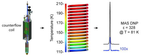
Cryogenic sample temperatures can enhance NMR sensitivity by extending spin relaxation times to improve dynamic nuclear polarization (DNP) and by increasing Boltzmann spin polarization. We have developed an efficient heat exchanger with a liquid nitrogen consumption rate of only 90 liters per day to perform magic-angle spinning (MAS) DNP experiments below 85 K. In this heat exchanger implementation, cold exhaust gas from the NMR probe is returned to the outer portion of a counterflow coil within an intermediate cooling stage to improve cooling efficiency of the spinning and variable temperature gases. The heat exchange within the counterflow coil is calculated with computational fluid dynamics to optimize the heat transfer. Experimental results using the novel counterflow heat exchanger demonstrate MAS DNP signal enhancements of 328 ± 3 at 81 ± 2 K, and 276 ± 4 at 105 ± 2 K.
Keywords: Dynamic nuclear polarization, solid-state NMR, magic-angle spinning, cryogenic MAS, heat exchanger, electron decoupling, pulsed DNP
Graphical Abstract
2. Introduction
Magic-angle spinning (MAS) nuclear magnetic resonance (NMR) is a powerful technique to study the structure and dynamics of an array of molecular architectures important to biology and materials science [1–6]. However, the small magnetic moments of nuclear spins result in inherently small NMR signal intensity. Nuclear spin alignment is poor at room temperature thermodynamic equilibrium due to the relatively weak Zeeman interaction. Cooling samples can significantly boost NMR sensitivity by enabling continuous wave dynamic nuclear polarization (DNP), and increasing thermal spin polarization [7–12].
DNP boosts NMR sensitivity by using microwave energy to transfer electron spin polarization to nuclear spins[13,14]. Many contemporary MAS DNP experiments employ exogenous stable organic radicals and continuous wave DNP mechanisms [15–18]. However, continuous wave DNP mechanisms have a steep inverse temperature dependence, resulting in smaller signal enhancements at room temperature [19,20]. Decreasing sample temperatures lengthens electronic and nuclear spin relaxation and increases continuous wave DNP transfer efficiencies.
Cryogenic MAS combined with DNP results in substantial gains in sensitivity and requires nitrogen or helium for bearing, drive, and variable temperature gas streams. Whereas helium MAS instruments often operate in closed loop systems with large initial installation costs [10,12], cryogenic nitrogen based MAS spectrometers are less expensive to build, but can consume a considerable amount of liquid nitrogen during operation. Liquid nitrogen consumption rates depend on rotor sizes and spinning frequencies, but are in the range of 200–700 L/day. To decrease operational costs of performing MAS DNP experiments below 85 K, we have designed and implemented a counterflow heat exchanger that reduces the total nitrogen consumption rate to 90 L/day. The novel heat exchanger was integrated into a custom 7 Tesla DNP NMR spectrometer. This paper describes the cryogenic and mechanical engineering of the heat exchanger and provides experimental verification of the improvements in cryogen usage and NMR sensitivity from DNP.
3. Instrumentation Design
3.1 Design overview
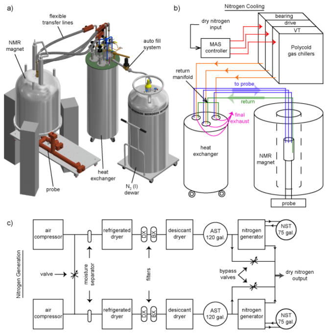
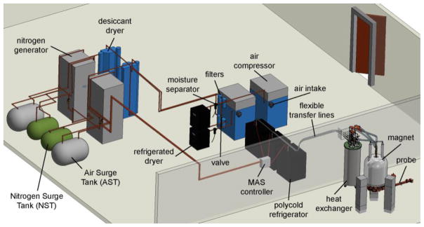
Fig. 1a (and Fig. S1) show the 7 Tesla spectrometer architecture and integration of the counterflow heat exchanger. Pure, dry nitrogen gas is generated by a system of compressors, separators, ballasts, and dryers followed by pressure regulation at room temperature, Fig. 1c and Fig. 2 [21,22]. Independent of the improvements in heat exchange technology we describe later, generation of pure nitrogen from air rather than from liquid nitrogen boil-off results in a substantial reduction in liquid nitrogen consumption. The following is a brief overview of the nitrogen generation.
Figure 1. Cryogenic system setup for low temperature MAS NMR.
a) CAD image exhibits the incorporation of the new heat exchanger in a 7 T DNP MAS NMR system (see Fig. S1). b) Flowchart shows the path of nitrogen gas as it cools to < 85 K for MAS and sample cooling. c) Flowchart shoes the generation of pure dry nitrogen from atmospheric air (see also Fig. 2). The stages of the two-stage set of filters between the dryers, models 2312N-1B1-DX and 2312N-1B1-BX, are labeled DX and BX respectively. Nitrogen surge tanks and air surge tanks are labeled NST and AST.
Figure 2. Physical layout of nitrogen generation system.
CAD image displays the physical layout of the entire nitrogen generation system from Fig. 1c and its coupling to the nitrogen cooling system and NMR probe. The components labeled as filters contain both the BX and DX filters.
Air is first compressed via two oil-free air compressors (Powerex, OH; Model: SEQ200720RIHPAJ). In nominal operation, the valve at the left-hand side of Fig. 1c is open and the eight pumps cycle on and off to reduce individual run time. The compressors provide a source pressure of 115–125 psi. The compressed air passes through a moisture separator to eliminate much of the water content before reaching the first drying stage. A refrigerated dryer cools the air to condense and further separate the remaining moisture (Deltech, FL; Model: HG50). A dual-tower, regenerative-desiccant dryer acts as a third drying stage (Hankison, FL; Model: HHL-90). This desiccant dryer lowers the dewpoint to below 77 K and continuously supplies dry compressed air to 120-gallon storage tank. A two-stage set of filters is located between the refrigerated dryer and desiccant dryer to eliminate trace quantities of oil, water, and dirt remaining in the compressed air (Parker-Balston, NY; Model: 2312N-1B1-DX and 2312N-1B1-BX). The dry compressed air is then purified through a dual-bed pressure swing adsorption nitrogen generator and stored in a 75-gallon storage tank (Parker Hannifin, MD; Model DB-20). Inside the nitrogen generator, the purification of compressed air to nitrogen is achieved through the adsorption of oxygen onto carbon molecular sieves. Once purified, the dry nitrogen is ready to enter the cooling and regulation system (Fig. 1b).
The heat exchanger is part of a three-stage strategy to minimize the liquid nitrogen required to cool nitrogen gas below 85 K for MAS. Fig. 1b and Fig. 3a depict the flow of nitrogen gas through the cooling system comprised of three distinct stages (initial, intermediate, and final). From the MAS controller onward, the nitrogen gas is split into three separate, yet nearly identical, paths (one for bearing, one for drive, and one for variable temperature). For simplicity, we will trace a single path in the following discussion. Initially, nitrogen is cooled to ~210 K using a Polycold gas chiller (Brooks, MA) before transfer to the heat exchanger, similar to previously described systems [22,23]. Inside the heat exchanger, the nitrogen is cooled to 80 K and then transferred to the NMR probe. The cold exhaust nitrogen gas from the NMR probe head is returned through a single vacuum-jacketed transfer line to the counterflow coil within the intermediate stage. Inside the counterflow coil, nitrogen gas from the refrigerators exchanges heat with the exhaust gas returning from the NMR probe. Finally, the nitrogen gas is cooled to 80 K with a stainless-steel coil partially submerged in liquid nitrogen (final stage).
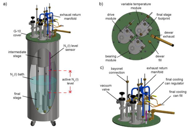
Figure 3. Heat exchanger assembly.
a) CAD image displaying the insertion of the individual modules into the liquid nitrogen dewar with the lower section submerged in liquid nitrogen bath. b) Top section view displaying the eclipse of the intermediate stage with the final stage (blue dashed circle) projected to the top surface of the intermediate stage. c) Top section of the heat exchanger assembly highlights the installment of the exhaust return manifold.
3.2 Triple module heat exchanger
Fig. 3a shows engineering drawings of the heat exchanger design which incorporates three identical modules within a flanged-top liquid nitrogen dewar (Cryofab, NJ). Each module of the heat exchanger cools one of three nitrogen gas lines for MAS and are operated in an independent manner to allow separate control over the pressure and temperature of each gas stream. Maintaining module congruency increases implementation flexibility and reduces repair downtime. A fourth module in reserve can replace any of the three modules in the event of a mechanical failure. However, we note the robust operation of the heat exchanger; over the course of three years we have not needed the reserve module.
The individual heat exchange modules are designed such that the footprint of the intermediate stage eclipses the footprint of the final stage (Fig. 3b). This facilitates ease of assembly and disassembly by permitting a single module to be inserted or removed while the other modules remain in place. Each module is inserted through a cutout in the fiberglass (G-10) dewar cover and is suspended such that the final stage remains submerged in the liquid nitrogen bath at ambient pressure.
A capacitive cryogenic liquid-level sensor, controller (Model 186, American Magnetics, TN), and solenoid valve regulate the level of the liquid nitrogen bath. The level of the liquid nitrogen bath is maintained above the final stage, but below the intermediate stage. In this region, the volume of liquid nitrogen per unit height is constant over a 23 cm range (see active N2(l) level, Fig. 3a). This provides a constant boil-off rate and ensures consistent cooling of the heat exchange modules.
3.3 Intermediate counterflow cooling stage
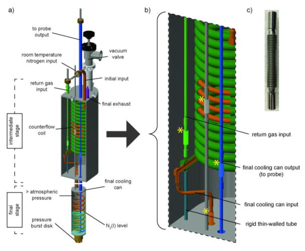
The heat exchanger modules contain intermediate and final stages, as shown in Fig. 4a,b. The intermediate stage is a concentric tube counterflow heat exchange coil housed in an evacuated chamber. Nitrogen gas from a refrigerator enters the inner tube of the counterflow coil (Fig. 4a, initial input, orange). The gas then proceeds down the coil axis exchanging heat with cold nitrogen exhaust gas from the NMR probe (110 ± 0.5 K), which has entered the outer tube of the counterflow coil at the return gas input (green) and is traveling up the axis of the coil to the final exhaust (purple).
Figure 4. Mechanical design of a single heat exchange module incorporating the counterflow coil.
a) CAD image of a single module highlights the intermediate and final stages. Detailed view of the inner vacuum space of the intermediate stage b) displays the jog in the tubing necessary for axillary installation of the modules, the rigid thin-walled tube which helps resist thermal compression induced strain, and the inner and outer tubes of the concentric tube counterflow heat exchange coil. c) Photo of a 316-stainless-steel bellow included in this design, indicated by yellow stars in Fig. 3b. For photos of the heat exchanger module assembly, see Fig. S3.
The exhaust return manifold in Fig. 3c splits the single, vacuum-jacketed exhaust line from the NMR probe head into three independent streams to pre-cool the bearing, drive, and variable temperature gases. Due to space confinements in the 89 mm bore of the magnet, the design is restricted to a single exhaust from the NMR probe. The manifold splits the single exhaust line to feed the outer portion of the counterflow coil in each module to exchange heat with incoming nitrogen.
The 4-inch inner diameter, 15-turn concentric tube counterflow heat exchange coil is wound from 0.035 in. wall, 0.625 in. outer diameter (outer tube) and 0.035 in. wall, 0.25 in. outer diameter (inner tube) 316 stainless-steel tubing (Exergy, NY). As noted above, the full heat exchanger assembly process is simplified by allowing the footprint of the final stage to be eclipsed by the footprint of the intermediate stage (Fig. 3b). To accomplish this, the output of the inner counterflow coil line bends to mate with the final stage (Fig. 4b and Fig. S2).
To prevent direct heat transfer between the nitrogen gas within the intermediate stage and the liquid nitrogen bath, the intermediate stage and transfer lines are evacuated. Provided the final stage remains submerged and the intermediate stage evacuated, the heat exchanger’s cooling power remains impervious to changes in the level of liquid nitrogen bath during fill/boil-off cycles and provides consistent cooling power and stable MAS (6 kHz ± 0.25% (15 Hz)). We note ±15 Hz is the spinning stability recorded over an hour of the system not under active PID control, which best represents any inherent instabilities in the spinning apparatus. Tighter regulation of the spinning frequency can be achieved with the use of valves or heaters integrated into a feedback control system.[24]
3.4 Intermediate cooling stage efficiency
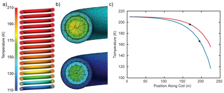
We used a computational fluid dynamics (CFD) software, Autodesk CFD 2017, to model the fluid flow and heat transfer within the counterflow heat exchange coil. This numerical analysis provides access to heat flux and temperature distribution information that is central to validating the benefits of recirculating cool nitrogen from the NMR probe head. The CFD program was configured to accommodate the establishment of materials with temperature functional properties to more accurately model flow over a wide temperature range. The inlet mass flows and temperatures were experimentally determined. Temperature of the hot stream inlet was 210 K with a mass flow of 0.815 g/s. The temperature of cold stream inlet was 110 K with a mass flow of 0.488 g/s. We assume incompressibility of the fluid which is generally applied for low Mach numbers. An advection scheme, Modified Petrov-Galerkin, and turbulence scheme, SST K-omega, were employed to precisely simulate boundary layer flow within the coils. The model reaches a quasi-steady state and validates the steady state simulation applied in this model.
Fig. 5a shows a cross-section of the temperature profiles for the inner and outer fluid (gas) lines. Fig. 5b displays the mesh used to solve the model, with appropriate mesh sensitivity near wall surfaces to model steep boundary layer velocities and temperature gradients. Care was taken to assign additional mesh density to the thin stainless-steel between fluid streams to allow development of a solid temperature gradient for accurate heat transfer. Fig. 5c plots bulk fluid temperatures along the helical path of the coil for flow in both directions, illustrating that the length of the heat exchanger is sufficient to allow near maximum heat transfer.
Figure 5. Computational fluid dynamics simulations determine the counterflow coil to be > 98% effective.
a) Simulated counterflow coil temperature profiles. b) Representative Finite Element Analysis mesh applied in the computational fluid dynamics simulations. c) Distribution of bulk fluid temperatures along the incoming (red) and exhaust return (blue) nitrogen gas streams. Arrows indicate the direction of nitrogen gas flow as up or down the coil axis.
From experimental inlet boundary temperatures, CFD was used to determine the outlet temperatures, Th,o= 152k and Tc,o=210k The maximum total heat transfer rate (qmax) can be found by qmax=CminΔT. Where Cmin is the lower heat capacity rate and ΔT = Th,i − Tc,i. In this case, both hot and cold streams have similar specific heats; therefore, the stream with the lower mass flow, i.e. the cold stream, will have the lower Cmin. From the simulation, there are multiple ways to find the heat transfer rate between the hot and cold streams of nitrogen. In the simulation outlined above, the total heat transfer rate was calculated through the integration of the heat flux across the stainless-steel barrier that separates the hot and cold streams and is found to be qsim = 49.9 W. From the inlet boundary temperatures qmax = 50.8 W. The effectiveness of the counterflow coil, defined as is nearly ideal at 0.98.
As a result of the intermediate stage cooling the nitrogen en route to the NMR probe to 152 K, the amount of liquid nitrogen required to cool the gaseous nitrogen stream to 77 K is reduced by 1.1 liters per hour per gas line. Assuming three identical heat exchange modules for bearing, drive and variable temperature, the recirculation system saves 79.2 liters of liquid nitrogen per day. The initial cooling stages (refrigerators) cool the room temperature gas inputs to 210 K (ΔT = 90 K) and save an additional 123 L/day. Therefore, without the initial or intermediate cooling stages, we estimate our system would consume 300 L/day for cooling purposes alone, and >500 L/day if the spinning gas originated from nitrogen boil-off rather than N2 gas generators.
3.5 Final cooling stage
Nitrogen gas from the intermediate stage exits the inner tube of the counterflow coil and descends through the vacuum-jacketed transfer line (orange) to the final stage (Fig. 4a). The final stage consists of a stainless-steel coil housed inside a can which contains liquid and gaseous nitrogen. This final cooling can is submerged in the liquid nitrogen bath. A separate, non-vacuum-jacketed fill line (gray) provides a source of nitrogen gas to adjust the level of liquid nitrogen within the can. This nitrogen gas inside the can is above ambient pressure and liquefies upon contact with the walls of the can. Raising the pressure within the can increases the level of liquid nitrogen and extends thermal contact time between the nitrogen contained within the coil and the liquid nitrogen in the can. Therefore, control of the pressure within the final stage allows for adjustment of its cooling power [9,25]. The pressure inside the can is regulated by a series of gauges, regulators and safety-relief valves located at the top of each module (Fig. 3c). The final stages cool the bearing, drive, and variable temperature nitrogen gas to just above its liquefaction point.
The coil in the final stage is wound from 0.020 in. wall, 0.25 in. outer diameter tubing and contains 7-turns with a 2 in. internal diameter (Jettron Products, NJ). The coil is housed inside a 3 in. outer diameter can. A burst disk made of 0.025 mm thick copper foil and sealed with indium wire at the bottom of the final cooling can prevents explosive events. During testing, the copper foil ruptured at a pressure of 3.8 bar in a liquid nitrogen bath.
Exiting the final stage, nitrogen gas moves up through a vacuum-jacketed transfer line and out of the heat exchange module to the NMR probe. Flexible vacuum-jacketed transfer lines (Precision Cryogenics, IN), which connect the polycold refrigerators to the heat exchanger, the heat exchanger to the NMR probe, and for the exhaust from the NMR probe to the heat exchanger, contain resistive Cernox sensors for temperature sampling (± 0.5 K).
3.6 Mechanical and Cryogenic Design Strategies
Weld-ready stainless-steel bellows (Mini-Flex, CA) were incorporated to minimize thermal compression induced strain when the modules are cooled from room temperature to operational temperatures near 77 K (Fig. 4c). One location of cryogenic induced mechanical stress is the joint at the bottom counterflow coil end. The top counterflow coil end is welded in two locations, whereas the bottom end is more flexible (Fig. S2). Reduction in temperature by as much as 220 K during operation leads to substantial reduction in the 6-meter path of the counterflow coil. The spring tension of the counter follow coil and flexibility of the bellow at the bottom of the counterflow coil alleviate strain induced upon cooling. A thin-walled tube welded between the bottom counterflow coil end and the bottom plate of the intermediate stage (Fig. 4b, turquoise) minimizes structural perturbation from its position at room temperature. The heat transfer through this thin-walled tube was calculated to be negligible.
Bayonet connections couple vacuum-jacketed transfer lines to the modules and the exhaust return manifold. The bayonets form air tight junctions and efficiently continue vacuum-jacketed insulation through the union of two components to reduce heat transfer. Heat exchanger components are machined from 300 series (non-magnetic) stainless-steel. Each joint is welded and helium leak-checked to ensure a robust and vacuum tight assembly (see Fig. S2).
4. Results and Discussion
4.1. Nitrogen consumption
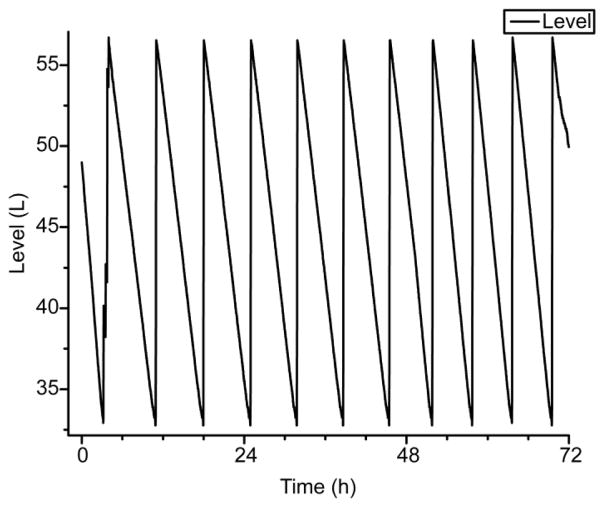
Fig. 6 shows the periodic fill/boil-off cycle of the autofill system over a three-day period of MAS at 5.2 kHz. Positive slopes correspond to fill periods, while negative slopes correspond to boil-off periods of the liquid nitrogen bath. The liquid nitrogen consumption rate is 90 L/day for cryogenic MAS at sample temperatures below 85 K.
Figure 6. Liquid nitrogen consumption of the heat exchanger.
Plot of the volume of liquid nitrogen bath in the heat exchanger dewar over three days. Positive slopes correspond to fill periods, while negative slopes correspond to heat exchanger boil-off periods. Individual boil-off periods were linearly fit and averaged over the 10 cycles shown above to find an average boil-off rate of 3.8 L/h or 91 L/day. Sample temperatures were maintained below 85 K while the MAS rotor frequency held constant at 5.2 kHz.
4.2. DNP Performance
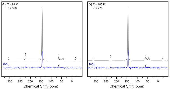
Fig. 7 shows 13C CP-MAS DNP spectra of urea at 81 ± 2 K and 105 ± 2 K. Signal enhancements from DNP are 328 ± 3 and 276 ± 4 respectively. The higher DNP enhancements at 81 K compared to 105 K, which is commonly achieved in commercial MAS DNP spectrometers, demonstrates the improvements in signal-to-noise available with our custom cryogenic instrumentation.
Figure 7. Temperature dependent DNP enhancements of 1 M [U-13C, 15N] Urea.
a) 13C CP-MAS DNP NMR spectra of 1 M [U-13C, 15N] urea with 20 mM AMUPol dissolved in cryoprotecting glassy matrix of d8-glycerol/D2O/H2O (60/30/10 v/v/v%) under 6000 ± 15 Hz MAS and a sample temperature of 81 ± 2 K are shown with (black line) and without microwave irradiation (blue line). b) The same sample is under 6300 ± 15 Hz MAS and a sample temperature of 105 ± 2 K.
1 M [13C,15N] urea was prepared with 20 mM AMUPol in a cryoprotecting glassy matrix of d8-glycerol/D2O/H2O (60/30/10 v/v/v%) to make up a 22 μL sample which was loaded into a sapphire rotor with a 3.175 mm outside diameter. 1H-13C CP-MAS spectra were obtained at 7.05 Tesla (300.182 MHz 1H Zeeman frequency) using a 1 ms 1H-13C cross-polarization period, rotor-synchronized 13C-π pulses of 6.25 μs and echo detection with 77 kHz 1H TPPM decoupling. The recycle delay was set to 3 seconds for recovery of longitudinal magnetization. Each spectrum is the average of 256 transients. The 3.2 mm MAS rotor is coupled to microwave irradiation generated from our custom built 198 GHz gyrotron using corrugated transmission lines and copper mirrors. For DNP, samples are irradiated with 36 W of 197.5 GHz microwaves. DMFit was used for peak-fitting and extraction of peak integrals [26]. The DNP enhancement at each temperature is calculated by taking the ratio of the peak integrals of spectra recorded with and without microwaves. Errors in the enhancements were determined by the RMS of the noise with respect to the intensity of the resonance in the microwave off spectra.
Temperatures were determined through measurement of the 79Br T1 relaxation time of a KBr powder sample using a saturation recovery experiment. After DNP enhancements were recorded, KBr was inserted into the probe and spun. Gas pressures and temperatures were adjusted until temperatures sensors in the vicinity of the sample read the same values for the rotor packed with KBr as the rotor with urea frozen in a glassy matrix. Fiber optic temperature sensors (Neoptix, Quebec) were positioned at four locations within the NMR probe head: top of the stator, bearing gas input of stator, variable temperature input of the stator, and between the bearing leg and the final variable temperature bend. KBr was packed into zirconia rotors for temperature calibration and magic angle optimization [27,28].
5. Conclusions and Outlook
We have described and characterized a novel heat exchanger which efficiently cools gases required for cryogenic MAS NMR spectroscopy. Together with a nitrogen gas generation system, the counterflow coil heat exchanger significantly reduces operational costs for MAS DNP. CP-MAS DNP signal enhancements of 328 on samples cooled to 81 K with a liquid nitrogen consumption rate of only 90 liters per day demonstrates the utility of the cryogenic instrumentation we have introduced. Automated liquid nitrogen fills permit continuous cryogenic MAS operation of the spectrometer for as long as five weeks, without detrimental ice formation. In the future, this heat exchanger will be connected to a 9.5 mm MAS DNP probe to yield further increases in NMR signal intensity. Spinning such rotors requires higher gas flows resulting in increased cryogen consumption. The new high-efficiency heat exchanger will be critical to limiting operational costs for such large-rotor cryogenic MAS DNP experiments.
Operation at nitrogen temperatures is sufficient to saturate continuous wave DNP mechanisms with high microwave power levels available with gyrotrons. However, cooling samples to below 25 K will be important to the development and application of electron decoupling, pulsed DNP, and other pulsed EPR methods in combination with MAS. The counterflow heat exchanger is currently being adapted for MAS using helium to achieve sample temperatures near the liquification point of liquid helium.
Supplementary Material
Highlights.
Counterflow heat exchanger design reduces nitrogen consumption to 90 L/day.
Computational fluid dynamics analysis describes heat exchanger performance.
80 K sample temperature yields DNP enhancement of 328.
Robust design and low H2O content permits extended continuous operation (>5 weeks).
Acknowledgments
Research reported in this publication was supported by the NIH (DP2-GM119131). We thank Lars Lindskog, Kurt Zilm, and Zayd Ma for helpful discussions.
Footnotes
Publisher's Disclaimer: This is a PDF file of an unedited manuscript that has been accepted for publication. As a service to our customers we are providing this early version of the manuscript. The manuscript will undergo copyediting, typesetting, and review of the resulting proof before it is published in its final citable form. Please note that during the production process errors may be discovered which could affect the content, and all legal disclaimers that apply to the journal pertain.
References
- 1.Hoop CL, Lin HK, Kar K, Magyarfalvi G, Lamley JM, Boatz JC, Mandal A, Lewandowski JR, Wetzel R, van der Wel PCA. Huntingtin exon 1 fibrils feature an interdigitated β-hairpin based polyglutamine core. Proc Natl Acad Sci. 2016;113:1546–1551. doi: 10.1073/pnas.1521933113. [DOI] [PMC free article] [PubMed] [Google Scholar]
- 2.Li S, Pourpoint F, Trébosc J, Zhou L, Lafon O, Shen M, Zheng A, Wang Q, Amoureux JP, Deng F. Host Guest Interactions in Dealuminated HY Zeolite Probed by 13C 27Al Solid-State NMR Spectroscopy. J Phys Chem Lett. 2014;5:3068–3072. doi: 10.1021/jz501389z. [DOI] [PubMed] [Google Scholar]
- 3.Andreas LB, Jaudzems K, Stanek J, Lalli D, Bertarello A, Le Marchand T, Cala-De Paepe D, Kotelovica S, Akopjana I, Knott B, Wegner S, Engelke F, Lesage A, Emsley L, Tars K, Herrmann T, Pintacuda G. Structure of fully protonated proteins by proton-detected magic-angle spinning NMR. Proc Natl Acad Sci U S A. 2016;113:9187–9192. doi: 10.1073/pnas.1602248113. [DOI] [PMC free article] [PubMed] [Google Scholar]
- 4.Loquet A, Giller K, Becker S, Lange A. Supramolecular interactions probed by 13C-13C solid-state NMR spectroscopy. J Am Chem Soc. 2010;132:15164–15166. doi: 10.1021/ja107460j. [DOI] [PubMed] [Google Scholar]
- 5.Erlendsson S, Gotfryd K, Larsen FH, Mortensen JS, Geiger MA, van Rossum BJ, Oschkinat H, Gether U, Teilum K, Loland CJ. Direct assessment of substrate binding to the Neurotransmitter:Sodium Symporter LeuT by solid state NMR. Elife. 2017;6:1–9. doi: 10.7554/eLife.19314. [DOI] [PMC free article] [PubMed] [Google Scholar]
- 6.Tuttle MD, Comellas G, Nieuwkoop AJ, Covell DJ, Berthold DA, Kloepper KD, Courtney JM, Kim JK, Barclay AM, Kendall A, Wan W, Stubbs G, Schwieters CD, Lee VMY, George JM, Rienstra CM. Solid-state NMR structure of a pathogenic fibril of full-length human α-synuclein. Nat Struct Mol Biol. 2016;23:1–9. doi: 10.1038/nsmb.3194. [DOI] [PMC free article] [PubMed] [Google Scholar]
- 7.Thurber KR, Tycko R. Biomolecular solid state NMR with magic-angle spinning at 25 K. J Magn Reson. 2008;195:179–186. doi: 10.1016/j.jmr.2008.09.015. [DOI] [PMC free article] [PubMed] [Google Scholar]
- 8.Carravetta M, Johannessen OG, Levitt MH, Heinmaa I, Stern R, Samoson A, Horsewill AJ, Murata Y, Komatsu K. Cryogenic NMR spectroscopy of endohedral hydrogen-fullerene complexes. J Chem Phys. 2006;124:1–13. doi: 10.1063/1.2174012. [DOI] [PubMed] [Google Scholar]
- 9.Allen PJ, Creuzet F, De Groot HJM, Griffin RG. Apparatus for low-temperature magic-angle spinning NMR. J Magn Reson. 1991;92:614–617. doi: 10.1016/0022-2364(91)90357-Y. [DOI] [Google Scholar]
- 10.Lee D, Bouleau E, Saint-Bonnet P, Hediger S, De Paëpe G. Ultra-low temperature MAS-DNP. J Magn Reson. 2016;264:116–124. doi: 10.1016/j.jmr.2015.12.010. [DOI] [PubMed] [Google Scholar]
- 11.Hackmann A, Seidel H, Kendrick RD, Myhre PC, Yannoni CS. Magic-angle spinning NMR at near-liquid-helium temperatures. J Magn Reson. 1988;79:148–153. doi: 10.1016/0022-2364(88)90331-9. [DOI] [Google Scholar]
- 12.Matsuki Y, Nakamura S, Fukui S, Suematsu H, Fujiwara T. Closed-cycle cold helium magic-angle spinning for sensitivity-enhanced multi-dimensional solid-state NMR. J Magn Reson. 2015;259:76–81. doi: 10.1016/j.jmr.2015.08.003. [DOI] [PubMed] [Google Scholar]
- 13.Carver TR, Slichter CP. Polarization of nuclear spins in metals. Phys Rev. 1953;92:212–213. doi: 10.1103/PhysRev.92.212.2. [DOI] [Google Scholar]
- 14.Wollan DS. Dynamic nuclear polarization with an inhomogeneously broadened ESR line. I. Experiment. Phys Rev B. 1976;13:3671–3685. doi: 10.1103/PhysRevB.13.3686. [DOI] [Google Scholar]
- 15.Jagtap AP, Geiger MA, Stöppler D, Orwick-Rydmark M, Oschkinat H, Sigurdsson ST. bcTol: a highly water-soluble biradical for efficient dynamic nuclear polarization of biomolecules. Chem Commun. 2016;52:7020–7023. doi: 10.1039/C6CC01813K. [DOI] [PubMed] [Google Scholar]
- 16.Thurber KR, Tycko R. Theory for cross effect dynamic nuclear polarization under magic-angle spinning in solid state nuclear magnetic resonance: The importance of level crossings. J Chem Phys. 2012;137 doi: 10.1063/1.4747449. [DOI] [PMC free article] [PubMed] [Google Scholar]
- 17.Corzilius B, Smith AA, Griffin RG. Solid effect in magic angle spinning dynamic nuclear polarization. J Chem Phys. 2012;137 doi: 10.1063/1.4738761. [DOI] [PMC free article] [PubMed] [Google Scholar]
- 18.Song C, Hu K-N, Joo C-G, Swager TM, Griffin RG. TOTAPOL: A Biradical Polarizing Agent for Dynamic Nuclear Polarization Experiments in Aqueous Media. J Am Chem Soc. 2006;128:11385–11390. doi: 10.1021/JA061284B. [DOI] [PubMed] [Google Scholar]
- 19.Ni QZ, Daviso E, Can TV, Markhasin E, Jawla SK, Swager TM, Temkin RJ, Herzfeld J, Griffin RG. High Frequency Dynamic Nuclear Polarization. Acc Chem Res. 2013;46:1933–1941. doi: 10.1021/ar300348n. [DOI] [PMC free article] [PubMed] [Google Scholar]
- 20.Sauvøe C, Rosay M, Casano G, Aussenac F, Weber RT, Ouari O, Tordo P. Highly Efficient, Water-Soluble Polarizing Agents for Dynamic Nuclear Polarization at High Frequency. Angew Chemie Int Ed. 2013;52:10858–10861. doi: 10.1002/anie.201304657. [DOI] [PubMed] [Google Scholar]
- 21.Barnes AB, Markhasin E, Daviso E, Michaelis VK, Nanni EA, Jawla SK, Mena EL, DeRocher R, Thakkar A, Woskov PP, Herzfeld J, Temkin RJ, Griffin RG. Dynamic nuclear polarization at 700MHz/460GHz. J Magn Reson. 2012;224:1–7. doi: 10.1016/j.jmr.2012.08.002. [DOI] [PMC free article] [PubMed] [Google Scholar]
- 22.Matsuki Y, Idehara T, Fukazawa J, Fujiwara T. Advanced instrumentation for DNP-enhanced MAS NMR for higher magnetic fields and lower temperatures. J Magn Reson. 2016;264:107–115. doi: 10.1016/j.jmr.2016.01.022. [DOI] [PubMed] [Google Scholar]
- 23.Matsuki Y, Takahashi H, Ueda K, Idehara T, Ogawa I, Toda M, Akutsu H, Fujiwara T. Dynamic nuclear polarization experiments at 14.1 T for solid-state NMR. Phys Chem Chem Phys. 2010;12:5799–5803. doi: 10.1039/c002146f. [DOI] [PubMed] [Google Scholar]
- 24.Mihaliuk E, Gullion T. Using heat to control the sample spinning speed in MAS NMR. J Magn Reson. 2011;212:249–253. doi: 10.1016/j.jmr.2011.07.009. [DOI] [PubMed] [Google Scholar]
- 25.Barnes AB, Mak-Jurkauskas ML, Matsuki Y, Bajaj VS, van der Wel PCA, DeRocher R, Bryant J, Sirigiri JR, Temkin RJ, Lugtenburg J, Herzfeld J, Griffin RG. Cryogenic sample exchange NMR probe for magic angle spinning dynamic nuclear polarization. J Magn Reson. 2009;198:261–270. doi: 10.1016/j.jmr.2009.03.003. [DOI] [PMC free article] [PubMed] [Google Scholar]
- 26.Massiot D, Fayon F, Capron M, King I, Le Calvé S, Alonso B, Durand JO, Bujoli B, Gan Z, Hoatson G. Modelling one- and two-dimensional solid-state NMR spectra. Magn Reson Chem. 2002;40:70–76. doi: 10.1002/mrc.984. [DOI] [Google Scholar]
- 27.Thurber KR, Tycko R. Measurement of sample temperatures under magic-angle spinning from the chemical shift and spin-lattice relaxation rate of 79Br in KBr powder. J Magn Reson. 2009;196:84–87. doi: 10.1016/j.jmr.2008.09.019. [DOI] [PMC free article] [PubMed] [Google Scholar]
- 28.Frye JS, Maciel GE. Setting the magic angle using a quadrupolar nuclide. J Magn Reson. 1982;48:125–131. doi: 10.1016/0022-2364(82)90243-8. [DOI] [Google Scholar]
Associated Data
This section collects any data citations, data availability statements, or supplementary materials included in this article.


