

Abstract
Developing new tools to better understand disorders of the nervous system, with a goal to more effectively treat them, is an active area of bioelectronic medicine research. Future tools must be flexible and configurable, given the evolving understanding of both neuromodulation mechanisms and how to configure a system for optimal clinical outcomes. We describe a system, the Summit™ RC+S “neural coprocessor,” that attempts to bring the capability and flexibility of a microprocessor to a prosthesis embedded within the nervous system. The paper describes the updated system architecture for the Summit™ RC+S system, the five custom integrated circuits required for bidirectional neural interfacing, the supporting firmware/software ecosystem, and the verification and validation activities to prepare for human implantation. Emphasis is placed on design changes motivated by experience with the CE-marked Activa™ PC+S research tool; specifically, enhancement of sense-stim performance for improved bi-directional communication to the nervous system, implementation of rechargeable technology to extend device longevity, and application of MICS-band telemetry for algorithm development and data management. The technology was validated in a chronic treatment paradigm for canines with naturally-occurring epilepsy, including free ambulation in the home environment, which represents a typical use case for future human protocols.
Keywords: neural interface, CMOS circuit, implantable system, low noise low power amplifier, embedded DSP
I. Introduction
While implantable systems exist today that modulate the nervous system for treatment of neurological disorders [1], [2], [3], there is still a need for advancing neurotechnology to better serve patient populations with improved outcomes [4]. One strategy gaining traction is to apply electronic technology as a “bioelectronic medicine” [5], where neural activity is precisely modulated in response to physiological signals to restore function. The emerging synthesis of neuroscience and technology, combined with the need to improve treatment for the neurological diseases that will be discussed here, make this a timely opportunity.
The bioelectronic medicine framework helps motivate the notion of a neural coprocessor [6]. The neural coprocessor framework seeks to advance from the historical concept of neuromodulation replacing a surgical lesion with a “stimulation lesion [7]” to the concept of designing a prosthetic system that provides adaptable, dynamic therapy to augment or regulate unhealthy neural circuits. A key feature of these designs includes real-time responsiveness to symptoms and intentions, informed by design principles at the intersection of biology and engineering.
To support this framework, we present an overview of the design of the Summit™ RC+S system, an implantable, investigational neural coprocessor for exploring new methods to treat neurological disorders. The first section motivates the Summit™ system requirements, including learning from the deployment of Activa™ PC+S system in several hundred human subjects, across multiple disorders. The implementation of additional risk mitigation sub-systems for automated algorithms, consistent with EN 60601-1-10 Physiologic Control methods, are also reviewed to motivate architectural design choices. The next section discusses the design of the hardware system, including five custom integrated circuits (IC): 1) a flexible stimulation IC capable of constant current stimulation, 2) a mixed-signal sensing IC with improvements in bi-directional (sense-stim) performance and noise floor, 3) a microcontroller which provides flexibility to download updated firmware as new features are developed, and two multi-function ICs which support 4) integrated filters and interface protection, as well as 5) power supplies, battery recharge, and MICS-band telemetry capability; the encapsulation of the chipset into a predicate 13.7 cc titanium case, and integration with modular lead systems are also briefly covered. The supporting firmware and software ecosystem of the hardware system is then discussed, including the use of an application programming interface (API) to allow for accelerated prototyping of new therapy concepts. Finally, system technology validation is demonstrated using a representative use-case treating epilepsy in canines. Future deployment activities and design limitations complete the discussion.
II. Design Inputs for a Neural Coprocessor
This section provides an overview of the current state-of-the-art in neural coprocessing concepts, proposes a physiologic control framework for designing a safe coprocessing system, reviews lessons-learned from the Activa™ PC+S system deployment, and summarizes the resulting system specifications.
i. Experience with Neural Coprocessor Prototypes
The potential for neural coprocessors is being explored in several ongoing investigational human studies. For example, the Activa™ PC+S system has been used to create novel thalamocortical circuit connections in patients with essential tremor, Tourette’s, and Parkinson's disease as part of the NIH BRAIN initiative [8], [9], [10]. To help illustrate the elements of a neural coprocessing system, we will analyze an adaptive deep brain stimulation example from essential tremor.
Essential tremor results in uncontrollable shaking symptoms appearing during attended movement. While therapeutic stimulation might only be required during motion [11], first-generation systems stimulate continuously. Continuous operation consumes excess power, and can result in unwanted clinical side-effects such as dysarthria, as clinicians try to balance efficacy against side-effects. To address this trade-off, investigators are interested in exploring a more adaptive approach to stimulation, based on a patient’s real-time needs.
To build a more responsive therapy for essential tremor, the investigational neural coprocessor described in [8] uses an additional implanted electrode to detect the natural cortical beta desynchronization correlated with movement intention. When intention is detected, the sub-cortical thalamic stimulation is increased to prevent the onset of tremor; when the motor intention signal disappears (beta resynclironization), the stimulation is ramped back down. This algorithmic concept is illustrated in Figure 1, highlighting the adaptive stimulation in the thalamus as a response to cortical control signals in a chronically-implanted human subject.
Figure 1:
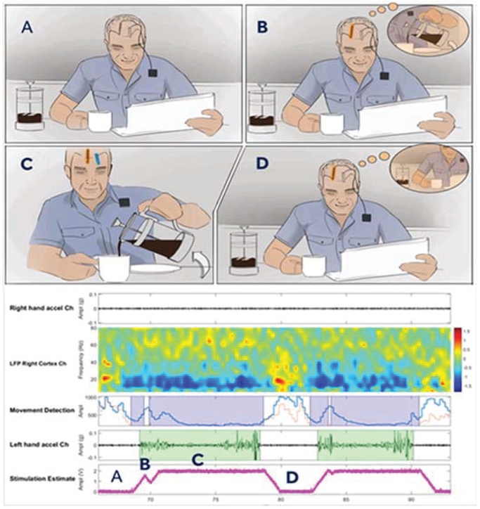
A representative neural co-processor application. Panel A represents a resting state with implanted depth and cortical leads. Panel B represents the intention to begin pouring drink detected on the cortical sensing lead. Panel C illustrates stimulation turning on and successfully pouring. Panel D returning to rest. Fully embedded cortical sensing movement-related beta desynchronization being utilized to control sub-cortical thalamic stimulation in an essential tremor subject. Note that as the patient moves (highlighted in green), the low frequency signals desynchronize around 20Hz, and the stimulation amplitude increases [9].
Similar thalamocortical network controllers were prototyped in Parkinson’s disease and Tourette’s, with a goal to adjust for variations in pharmacological state and tic behavior, respectively [10], [12], [13]. While the current examples describe brain-based systems, the potential applications of a neural coprocessor also extend into the periphery and organ systems [5], [14], [15]. Creating a general-purpose system – as much as feasible—is a key design goal.
A critical take-away from all current prototypes is the need for simultaneous sensing and stimulation at the neural interface. In fact, the algorithmic requirement for detecting sub-microvolt-level physiological signals coincident with volt-level stimulation is a critical design input for all future neural coprocessors. While the Activa™ PC+S system had capability for prototyping of the algorithm described here, it also highlighted the need for expanded design margin, especially for sensing from sub-cortical targets like the basal ganglia or thalamus [16].
ii. Neural Coprocessor Risk Framework
The design of a neural coprocessor requires thoughtful consideration for the risk profile of the integrated bioelectronic-physiological system. In particular, the system designer needs to plan for limiting the potential downside of autonomous operation, in addition to exploiting the upsides. This is especially true when applying novel scientific concepts such as those presented in figure 1 and 11.
Figure 11:
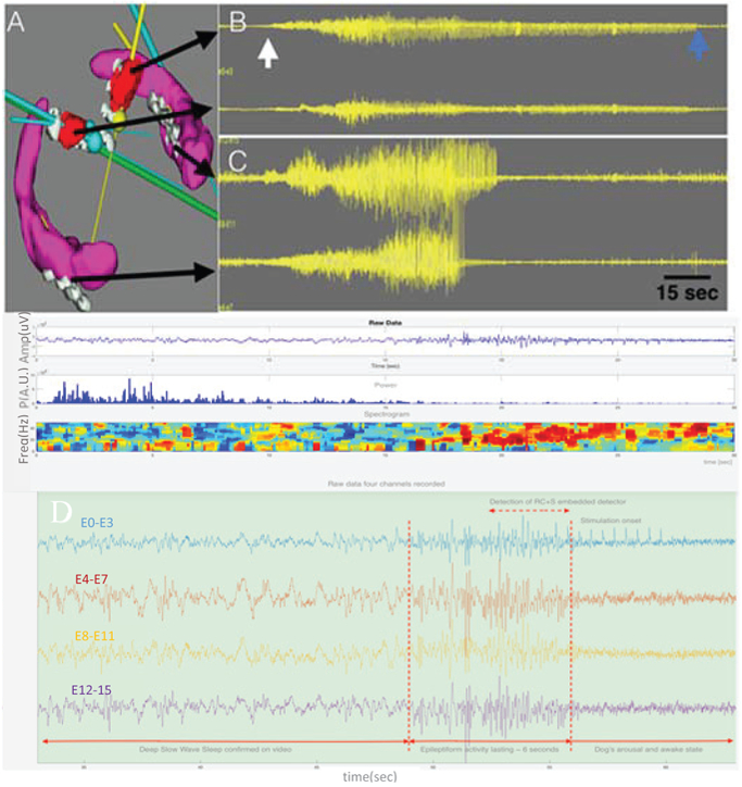
Bilateral ATN and HC targets and intracranial EEG. A) Bilateral HC (purple) and ATN (red) target volumes and electrodes (gray). Multiple electrodes are in each target. B & C) Four channels of EEG. From top to bottom: Left ATN, Right ATN, Left HC, and Right HC recordings. The white arrow marks the onset of a seizure and the blue the seizure offset. The seizure is seen in all the electrodes, but interestingly the seizure terminates in all electrodes at different times. The longest seizure discharge is in the left ATN. ATN=anterior thalamic nucleus. HC=hippocampus. D) Detection of interictal epileptiform activity longer than 1 second (embedded detector). Onset of the activity is marked together with onset of stimulation with delay about a second. The dog arouses from deep sleep to awake (confirmed on video).
These risk and design considerations are well captured by the IEC 60601-1-10 standard: general requirements for basic safety and essential performance – collateral standard: requirements for the development of physiologic closed loop controllers [17]. Although intended for external control algorithms, applying this standard as a guiding set of principles can help ensure robust operation of a bioelectronic system.
Referencing Figure 2a, the base bioelectronic system can be modeled as a physiological closed loop controller with several key subcomponents. The terminology in the figure is derived from the IEC standard, with core operational blocks highlighted in blue, and risk considerations and mitigations in light brown. How these mitigations may be considered in a de novo neural coprocessor system is detailed below, where we will again use the essential tremor example to highlight specific concepts.
Figure 2:
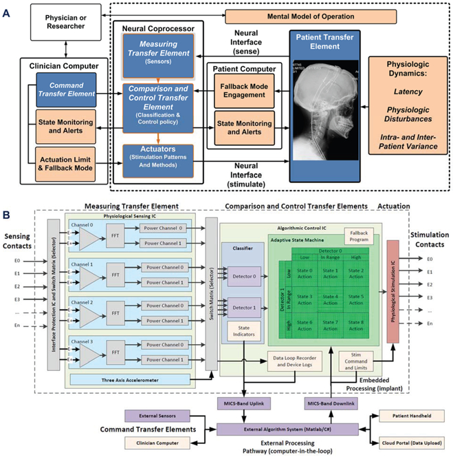
Functional block diagram of the neural co-processor using the IEC 60601-1-10 framework for a physiologic control system, including explicit terminology for key functional blocks and risk mitigations. A) system functionality is partitioned within the internal neural co-processor, including sensing, algorithm and stimulation blocks, and the external support system for configuring the device. Key functional blocks are in blue, with risk mitigation blocks in tan. B) the reduction of the abstracted system diagram to specific functional blocks in the Summit™ RC+S system signal pathway, including key circuit partitioning, embedded and external processing pathways, and risk mitigation blocks.
Human factors – providing a mental model of the control algorithm:
a mental model of algorithm operation helps the clinical investigator intuitively set up the closed loop parameters, test operation, and debug issues. For example, in the case of the essential tremor device, the mental model of operation is that the event-related desynchronization from patient intention turns stimulation on, while resynchronization turns stimulation off. The specific mental model of operation will be disease and protocol specific. Differences in operation will be reflected in how the device is configured through the firmware/software interface.
Measuring transfer element – characterizing the expected intra- and inter-patient variability:
the intent is to ensure the sensing interfaces and algorithms can appropriately capture the breadth of signals that will be seen by the control loop. For example, the investigator will want to ensure their sensor has the required dynamic range and specificity for the intended patient population. This variability might include the frequency content of the signal and the signal to noise ratio of the bioelectrical signal. Variations in the signal require flexible tuning of the signal processing chain and detection classifiers provided by the developed coprocessor.
Patient transfer element – understanding latency requirements:
the intent is to understand the temporal dynamics between when an actuation adjustment is made, when it impacts the physiological system, and when the response might be detected. For example, while measurable physiological changes might occur on the order of seconds for an essential tremor therapy, other disease states like epilepsy or dystonia might require months for the physiological changes to fully emerge [18]. It is important to understand these delays, because trying to increase the control loop response beyond these temporal limits might result in excessive stimulation levels, or even control-loop-induced oscillations. However, if the control loop is ran at too slow of a rate then algorithms may miss the window where stimulation adjustment is needed, resulting in poor therapeutic outcomes. This temporal balance of the system’s responsiveness and latency requires careful consideration when designing an embedded or distributed algorithm. A quantitative example of this was discussed in Figure 1 showing an example where LFP changes are detected on 400ms delays followed by stimulation changes within 1s of motion onset.
Control transfer element – defining an actuation limit:
building on the last point, the clinical investigator should consider the impact of actuation levels on the physiology of the patient; note that these can include both higher and lower limits. For example, the investigator might want to set an upper limit to stimulation for preventing excessive side-effects, and a lower limit to guarantee a minimum of therapy is provided. In addition, the investigator might also want to consider limiting the ramp rates for changing stimulation to avoid side-effects like paresthesia or after-discharge events [19]. The use of a clinician-focused programmer to configure a safe, pre-specified operating space for stimulation helps to implement these actuation limits explicitly; the closed-loop algorithms are never allowed outside of the clinician-restricted stimulation parameter space.
Control transfer element – defining a fallback mode:
despite an investigator’s best efforts, one of the closed loop system’s core elements might encounter an issue that undermines performance and results in patient discomfort. An example of this would be excessive (beyond IEC specification) electromagnetic interference corrupting the physiological sensing chain, and thereby leading to misleading information. An investigator should consider how to design a fallback mode that allows the bioelectronic system to enter a well-defined state with a margin of safety. A typical example is open loop actuation with a predetermined level deemed acceptable to the patient by clinician. To implement this method, a pre--determined open-loop stimulation program can be pre-loaded into the neural coprocessor prior to initiation of closed-loop operation. If the patient or clinician signals an emergency, or the device resets, the device will immediately go to this predefined, and constrained, mode of operation.
Control transfer element – providing state indicators:
the intent of the state indicator is to provide critical information to the user (patient and clinician) on the operating mode of the control loop. The presentation of this information should include human factors considerations so that the information is meaningful and actionable. For example, in a typical neurostimulator, the parameter settings for stimulation and state of stimulation are available to both the clinician and the patient, with the appropriate level of detail to provide the required data without being confusing. A system which uses wireless telemetry can provide full monitoring of all state information, including timestamps for state transitions. These logs provide both immediate information on device state, as well as logging all transitions within the system for follow-up.
Training and Fault analysis – providing data logs for training and algorithm ‘debug’:
The inclusion of a patient- or algorithm-enabled data recorder can help to understand both how the physiologic control algorithm performs in normal operation for training purposes, or capture failure events that require modification of the algorithm or additional patient warning. Many issues can arise in the real-world that might compromise the performance of the base algorithm.
For example, the Activa™ PC+S system can be configured to store patient-triggered events correlating to clinical state. These recordings feed into a database for continuous algorithm refinement [20]. In addition, sensor-based detection events can also be stored using the embedded data recorder. These data logs provide supplementary data to standard device logging such as capturing all changes in parameter states and periodic electrode impedance monitoring.
In summary, we adopt the design guidance of 60601-1-10 as a key input for our system-level design requirements. While following these guidelines does not guarantee absolute safety and reliability, the systematic process of identifying risk and mitigations does help maximize the robustness of the intelligent system in real-world deployment.
iii. Lessons-learned from Activa™ PC+S System
The neural co-processing systems enabled by the Activa PC+S ™ system were pilot concepts that provided insight into both brain physiology and medical device design. Lessons-learned aid in defining new requirements for neural coprocessor design. While these limitations were recently covered in [10], they are summarized here with the added context of the coprocessor design framework. We note that opportunities to enhance the next generation of neural processing tools span the entire system.
For example, gathering data from neural networks proved to be a laborious process. Ideally, the system should be able to record and telemeter brain signals during activities of daily living, with high throughput and at least arms-length distance. The Activa ™ PC+S system’s relatively slow (11.7kbps) and proximal (~2cm) telemetry link, combined with limited data storage capability (1MB), ultimately limited the practical data-gathering capability. To address this shortcoming, we switched to a MICS-band radio that could support continuous streaming of data at a meter of distance; but the inclusion of the radio also helped motivate the pivot to a rechargeable system.
In addition to the opportunities to improve the data collection capabilities, there was room for improvement in device longevity. The Activa™ PC+S system is a primary cell system, and so minimizing power consumption is an important design constraint to avoid a significant device longevity impact from running research studies. Continuous data streaming, in particular, could significantly undermine device longevity with every experimental session. With no greatly improved primary battery chemistry available (e.g. >5x improvement), we chose to implement a rechargeable system on the Summit™ RC+S system. Rechargeable systems support the sense and transmission functionality while maintaining device longevity; and in practice, greatly extending it. The specifications then shift to ensuring an acceptable user experience, including device safety and recharge intervals.
Finally, the Activa™ PC+S device periodically experienced artifacts due to a finite common-mode rejection ratio (CMRR). Finite CMRR allowed for electrocardiogram (ECG) and stimulation to contaminate the signal path in a sub-set of implants [10], [16]. While these artifacts could generally be mitigated with either implant technique or parameter constraints, we wished to eliminate the burden for our users. For the Summit RC+S system, we specified design changes like active-stimulation recharge and improved connector seals to further improve artifact rejection. Active-stimulation recharge (discussed in greater detail in section III) provides charge balance of the electrode tissue interface faster than passive recharge, and thereby limits the duration of signal contamination. While active recharge requires more energy use, the use of a rechargeable battery enables this capability.
In summary, the Activa™ PC+S system experience motivated the inter-related design changes of MICS-band telemetry, rechargeable battery technology, and system-level artifact mitigations. The aim is to improve the Summit RC+S’s performance in protocols and enhance the user experience.
iv. Summit RC+s System Requirements overview
The Summit RC+S system is designed to ultimately support investigational research in neuromodulation using human subjects. This goal requires balancing next generation neural coprocessing opportunities, technology maturity, and residual patient risk. The summary of system requirements representing this compromise is listed in Table 1.
Table 1:
Neural Coprocessor system specifications.
| LFP/ECoG Sensinq | Embedded Algorithm Characteristics | ||
|---|---|---|---|
| Operating Power Dissipation (Time Domain) | 50W/channel | Algorithm Power | <5μW/channel (embedded) |
| Operating Power Dissipation (Spectral Mode) | 500nW/channel | Algorithm Type (Embedded) | Support Vector Machines linear only (2 band power inputs per channel) and State Machines |
| Typical Function modes | Time domain/Fourier Transforms in DSP | Algorithm Upgrade Capability | In-vivo through telemetry and embedded bootloader |
| MUX, channels available PC Dual Lead Implant System Assumed | Input mux alows 16→4 down-selection of best channels for upload | Memory Buffer (Monitoring Diagnostics) | |
| Minimal Detectable Signal | <200nVrms | SRAM | 250kb |
| Spot Noise Spectral Density | <150 nV/√Hz | Stimulation Capability | |
| Bandpower Center Frequency | dc to 500Hz | Stimulation Channels | 8 for bilateral (4/lead) (unipolar/bipolar) |
| Bandwidth of Spectral Estimate | 1-20Hz (FFT determined) | Inertial Sensor | |
| CMRR/PSRR | >80dB | Operahng Power (3-axis Measurement) | 2μW |
| High Pass Comers | 0.05-8Hz | Inertial Algorithm Power Dissipation | 25μW (posture, activity, tremors, etc) |
| Input Range (Stim compliance) | > +/−10V | Sensitivity | 125mV/g (.01g/LSB) |
| Telemetry and Recharge Intervals | Dynamic Range | +/−5g (Falls, footsteps, high impact activity) | |
| Data Rate | 195kbits/s | Noise (X,Y axis) | 3.5 mgRMS (0.1-10Hz) |
| Data Capacity | 4 channels | Noise (Z axis) | 5 mgRMS (0.1-10Hz) |
| Data Streaming capability | 4 Time Domain at 250 or 500Hz, 2 Time Domain at 1kHz | Nonlinearity and Sensing Floor | <1%. 10mg any axis |
| Recharge Interval (100% streaming) | >24hrs | Shock Survival | >10,000g |
The partitioning of the system functionality is shown in Figure 2b and can be considered as two major sub-blocks supporting the 60601-1-10 framework: 1) an implantable hardware-firmware subsystem for neural interaction and running embedded algorithms, and 2) a supporting firmware-software system for communicating, recharging, streaming and analyzing data. This architecture enables management of distributed algorithms and configuration of the system for customization at the disease-state and patient-specific levels.
This functional system partitioning evolved from the Activa PC+S ™ system experience [21], [22]. As motivated earlier [10], the key changes include MICS-band telemetry, wireless-inductive recharging, the ability to support four leads (with 4 electrodes each) simultaneously, and enhanced digital signal processing. The Summit system also adopted an application-programming-interface (API) command set to aid the investigator in rapid development of novel system configurations. In aggregate, these changes provide a more flexible enviromnent for prototyping therapy concepts.
The specific research tool configuration is determined by the investigator in the software enviromnent. Once the protocol-specific research goals are well understood, the coprocessor can be configured through the wireless telemetry link. For example, the sensing and stimulation electrode multiplexer selects the electrodes which contain the most relevant physiologic information. As the signals are acquired, they can be processed either inside of the system through hardware subroutines, or streamed externally for more complex analysis. Stimulation adjustments are made with either the embedded classifiers, which selects the stimulation action to take based on a state table, or through command updates telemetered back down to the stimulator. Within each protocol, the choice between using embedded processing or distributed control is set by the tradeoff of classifier and control policy complexity versus latency of telemetry and power consumption.
III. Summit RC+S Hardware Design
This section describes the full hardware system for the Summit™ RC+S system, including custom ICs, assembly into an implantable hermetic package, and integration of all supporting components such as rechargers and electrodes.
i. Chipset Overview
To provide the desired system functionality, the IC system is partitioned into functional sub-blocks. The mapping of functionality (Figure 2b) into specific ASICS is illustrated in Figure 3.
Figure 3:
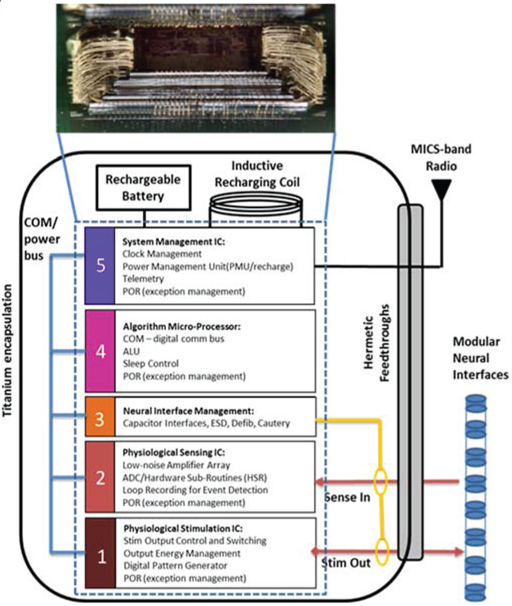
Mapping the neural coprocessor block diagram into an integrated circuit die stack comprising five custom integrated circuits. Each modular function uses an optimal circuit technology: for example, ICs 1 and 5 use .8μm HV CMOS for stimulation and analog infrastructure, IC 2 uses a 0.25μm CMOS process for sensing and digital signal processing, IC 4 uses a .25μm flash process for micro processing and digital signal processing, and IC block 3 uses a proprietary process for interface protection. The telemetry module is a stand-alone module.
The system foundation is built on a .8μm HVCMOS stimulation engine, which repurposed a predicate commercial IC to ensure we provided the expected clinical benefit to patients. The mixed-signal, physiological sensing amplifier IC was designed in .25μm CMOS technology to leverage the improved digital signal processing capabilities in this smaller technology. This design choice allowed digital algorithm processing for analyzing both passive and evoked field potentials, as well as data loop recording, versus the analog approach of the Activa™ PC+S system. A .25μm CMOS flash-based algorithm processor provides system control and telemetry management through a MICS-band radio module. An .8μm HVCMOS system management IC provides the bandgap power supply generation, clock generation, and recharge interface. Finally, a fifth chip provides integrated passive filters for the entire signal chain.
Supplementary neural interface management, which is required to protect the integrated system from transient events like EMI, cautery and defibrillation, was implemented with discrete high-voltage component arrays that shunt across the electrode pathways as well as to the titanium package case. The arrays are designed to protect the system from high-energy transient events without impacting baseline sensing or stimulation performance.
The constraints on the system mechanical design dictated the IC partition. When planning the physical architecture of the implant, leveraging die stack technology is a technique to help minimize area. In addition, a key design decision was to leverage an existing commercially-released stimulation system and minimize system impact to the established infrastructure. Given these key constraints, our main design goal was to provide physiological sensing and algorithmic capability within an existing die stack, so to fit into the predicate’s mechanical packaging. Design overviews of specific ICs are provided next.
ii. Physiologic Stimulation IC
The foundational circuit for therapy delivery is the stimulation engine; the key specifications are shown in Table 2. The stimulation engine must maintain core capabilities for established therapies to ensure the expected patient benefit. To facilitate this requirement, the investigational design builds on a commercially-released system for spinal cord stimulation (Intellis™ system).
Table 2:
Stimulation IC Requirements
| Parameter | Performance |
|---|---|
| Current Capability (Istim) | .05-25.5 mA |
| Fractional Capability | Divisors of n/64*Istim |
| Pulse Width Capability | 20-450us |
| Rate Capability | 5-250Hz |
| Active Recharge ratio (stim/recharge) | .5-1.5x |
In addition to maintaining baseline therapeutic stimulation, enhancements were made to improve the capability of the system by adding monopolar (return to case) capability, which is used in most deep brain stimulation therapies. Monopolar stimulation also facilitates sensing during stimulation, by using common mode rejection to suppress the stimulation artifact by “sandwiching” the monopolar electrode between the two differential sensing electrodes. Rejecting stimulation artifact prior to amplification helps to prevent sense channel saturation, and eliminates some of the need for more complex artifact removal techniques [16]. The stimulation IC also has the ability to fractionalize stimulation and deliver specific current levels to multiple electrodes, although the impact of asymmetrical stimulation will slightly undermine the CMR of artifacts.
To help mitigate stim artifacts further, the stimulation IC uses active recharge to achieve charge balance in the stimulation pulse in a short time interval (order of stim pulse, 100uS) instead of the full passive recharge duration (order of stim period, 10mS). Using active recharge helps to both limit polarization effects and the duration that the electrodes are connected to the case for recharging; the former limits the amplifier blanking interval, while the latter helps to prevent susceptibility to ECG and motion artifacts due to the finite common-mode rejection performance of the electrode system. The net effect is to improve sense-during-stimulation operation.
Selecting the optimal active recharge ratio is a degree of freedom for enhancing performance. By optimizing the active recharge ratio, the investigator can limit the peak to peak input into the sense channel and avoid amplifier saturation. Minimizing stimulation peaks also improves the step response when stimulation parameters are changed, as the residual voltage on the electrode coupling capacitor approaches zero in this state. This is important for control algorithms that require fast turn-on and turn-off times.
The impact of the recharge changes was studied in a saline tank that models the enviromnent of the tissue-electrode interface [23]. Characterization results are summarized in Figure 4, highlighting the impact of active recharge, including ratio selection, on artifact sizes. Based on these results, we included the selection of the recharge ratio as a configurable register in the stimulation IC so that investigators could optimize artifact suppression in vivo.
Figure 4:

Bench-top evaluation of recharge techniques in a saline tank. This plot illustrates optimizing the active recharge ratio to both minimize peak to peak artifact with stim on, and also optimize the stim off step response.
iii. Physiologic Sensing IC
The physiology sensing IC was custom-designed for this application; a summary of key performance measures is shown in Table 3. To achieve a bi-directional interface, we designed the physiology sensing IC with attention to recording and processing signals in the presence of stimulation. Sensing during stimulation for sub-cortical neural circuits requires the ability to resolve 100nV/rtHz field potential signals in the presence of >1V, ~100uS pulse trains, with stimulation and sensing frequencies that are separated by as little as 10Hz [16]. The sensing IC can provide multiple representation of the signals based on the investigator’s needs. The sampled output of the sense chain can be assessed in the time domain, including stimulation markers for helping with evoked potential analysis, or a frequency analysis of the signal may be performed with a customized Fast Fourier transform (FFT) hardware subroutine. Note that the IC requirements includes recovery times for evoked potentials based on characterizations of sub-cortical brain regions such as the Fornix or Hippocampus [24]. Figure 5 illustrates the key enhancements to the sensing signal chain that help provide this capability, as well as the key characterization data. There are four key design changes in the front-end sensing electronics that are relevant for improving the sensing-during-stimulation capability: 1) a synchronous front end blanking switch, 2) filtering to attenuate the large common mode and differential mode stimulation artifacts that tend to occur outside of the local field potential (LFP) bands of interest (approximately 0.5-400Hz), 3) a fully differential amplifier design to further improve common mode rejection of stimulation artifacts, and 4) design techniques that remove the higher order harmonics of stimulation in the digitization stage to allow sampling at lower frequencies and avoid harmonic folding into the bands of interest; additional details for the sensing chain can be found in [25].
Table 3:
Sensing IC Requirements
| Parameter | Performance |
|---|---|
| Minimum Signal resolution | 100nV/rtHz |
| Gain | 250 V/V |
| Channels | 4 |
| High Pass Filter | .05, .5, 2.5, 8Hz |
| Sample Rate | 250, 500, 1000Hz |
| Evoked Potential Stim Recovery | 10-20ms |
Figure 5:
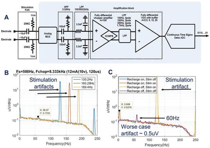
A) Block-diagram of the sensing signal chain [note that the 100nF and 3.3nF differentially-matched capacitors are in the passive array] B) sense-stimulation interactions with various frequencies C addition of recharge energy during sensing and stimulation for assessing worst-case artifacts.
System-level design can also mitigate artifacts, specifically careful management of sampling clocks and stimulation rates. Because of the finite data processing rates in the 1kHz range, and stimulation frequencies in the 50-200Hz range, aliasing into bands of interest is a challenge. By optimizing the stimulation frequencies and suppressing higher order harmonics through oversampling, a larger group of sense friendly stimulation frequencies can be obtained compared to the Activa PC+S; note that this process is automated for the user with the Summit RC+S [26].
In addition to removing higher order harmonics, it is also important to remove DC content in the time domain signal prior to performing the FFT function. This serves two benefits to the system performance: first, it removes DC component and prevents spectral bleeding into low-frequency LFP bands of interest; second, by suppressing the DC content using a high pass filter, the transient response to stimulation ramps during algorithm transitions is mitigated, which helps reduce artifacts in a responsive closed loop system.
The benefits of the high pass filter are illustrated in Figure 6. In this demonstration, we again are testing in the saline enviromnent described in Figure 4. Stimulation is being ramped up and down in 250ms. Panel 1 represents stimulation ramping up and down based on the input signal. Panel 2 shows the impact that high pass filtering the data prior to FFT has on improved step response recovery. Finally, panel 3 shows how the high pass filter reduces the step response input signal.
Figure 6:
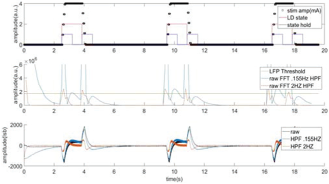
Evaluation of the impact of adding digital high pass filtering prior to FFT to remove DC offset and improve step response performance.
One cautionary note in the context of real-time algorithms is that care should be taken when selecting the sample rate and number of FFT points. Considering our risk items, latency considerations need to be assessed in the context of physiologic response times; the longer the FFT buffer is the longer it will take the FFT to settle from stimulation changes.
iv. Microprocessor and Telemetry
Given the decade-plus longevity of the device, flexible firmware programming is a key design goal to allow for system updates as new algorithms are prototyped. The microprocessor uses a flash-based process with supporting bootloader, which allows for feature enhancements to be implemented through firmware download capability. This processor core is a modified 68HC11 CPU, with design choices made to minimize current drain. For example, we adjusted doping profiles and adjusting transistor threshold voltages to minimize leakage current and lower threshold voltages; this was acceptable given our lower system clock. Additional system-level support blocks in this IC include watch dog timers and buses to control and communicate to other ICs in the integrated system. The main motivation for using the 68HC11 in this design lies in the large amount of infrastructure that was leveraged from the Intellis™ system. By leveraging the predicate communication platform, the design effort could be focused on optimizing the sensing and closed-loop capability of the system.
The microprocessor IC also is the main interface to a distance telemetry module which allows arm’s length communication to an external communication module. This communication occurs in the MICS-band and allows streaming of local field potentials on 4 independent channels sampled at 1kHz each. The .18μm MICS band IC includes four different communication modes. These modes provide a user tradeoff between range and data communication rate. The lower modes allow for long range communication at slower data rates while the higher modes are used more for LFP streaming applications where the external communication unit can be held closer to the patient to achieve high data rates.
v. Multi-Function ICs
Two multi-function IC’s are used in the system and support integrated filters and interface protection, as well as power supplies and battery recharge. The first IC is an integrated filter capacitor IC is a passive substrate that integrates 22 capacitors, from 1nF to 100nF. All capacitors are manufactured within ±20% tolerance using the High Voltage process from IPDiA™. The size of the chip is 6.95 × 8.88mm which enabled significant space saving on the integrated hybrid.
The second IC manages power supply and battery recharge. The IC provides a band gap reference and power supply for both digital and analog circuitry throughout the system. A “coulomb counter” measures current flow in and out of the battery, so that battery capacity can be continuously estimated to ensure that patients are aware of remaining operation time before required recharge, as well as time remaining for a given recharging session. To also support recharge, a PTAT (Proportional to Absolute Temperature) block is included to monitor device temperature. This measurement provides a key safety measure to insure device temperature is maintained within a safe operating range. Finally, a crystal-based clock generator at 100kHz is generated on this IC to provide the system clock for the multi-IC system.
vi. Rechargeable Battery and Recharge Management
Another key component to the neural co-processor is the power source. One of the lessons learned from the Activa PC±S ™ system was that trying to do research with a primary cell device comes at a cost to the patients from a device replacement perspective [27]. In several cases, researchers were limited in their protocols due to longevity-impact restrictions. As the researchers weigh longevity impact versus data quantity, it was clear that a rechargeable system would eliminate this constraint.
The Summit™ RC±S system leverages the rechargeable battery technology used in Intellis™ system [28]. Figure 7 illustrates some of the key characteristics that support a robust rechargeable battery technology extended research tool use. The first metric is battery capacity as a function of recharge cycles. Having the capacity remain at 90% for 3000 cycles represents an acceptable battery fade characteristic. In common usage, a neurologic product averages 1 recharge cycle per week over a 10-year period (~500 cycles). While this represents a typical deep brain stimulation Parkinson’s patient, we wanted to design for daily recharge to support continuous streaming throughout the protocol. The final important point of the battery performance is charge capacity vs charge time. Having a full recharge time of less than 1 hour is a significant improvement over prior medical devices, which could require over 8 hours for a full recharge. This is an important selling point to research subjects who desire minimal recharge burden.
Figure 7:
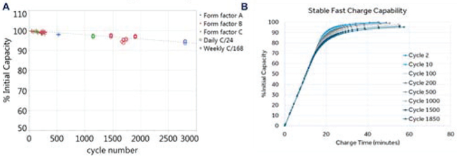
Summary of typical battery characteristics: A) capacity versus cycle number B) capacity versus time for recharging: the impact of stimulation cycles is also represented.
vii. Final Hardware Integration
The final integration requires sealing the integrated circuits, components and battery into a hermetic package that integrates with electrode interfaces to the nervous system. To start, the five ICs in the system are wire-bonded in a five-high integrated die stack, as shown in Figure 8.
Figure 8:
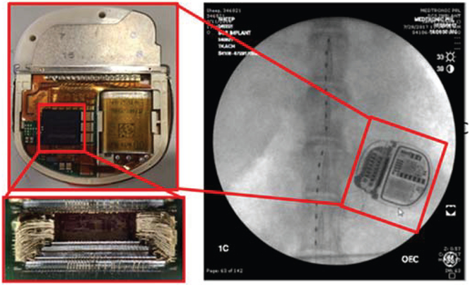
Integration of the integrated circuit stack into a final implantable pulse generator, which leverages the Intellis™ system 13.7 cc titanium case and 2×8 connector block. The connectors allow for modular lead connections to a variety of electrode configurations; the example shown is for a spinal cord stimulator in an ovine model.
The stack is then placed with components on a hybrid, electrically connected to the battery and hermetic feed-through pins, and seam-welded into the human-qualified mechanical package used in the Intellis™ system. The design advantage of leveraging an existing mechanical system approved for human use is experience with reliability-performance metrics, and the ability to reuse qualification testing like biocompatibility, biostability, drop testing, barometric tests, and sterilization. Screens and testing are performed at the component, hybrid and final device manufacturing steps.
To be useful as a neural coprocessor, the system needs a stable interface to the nervous system. We again leveraged leads and extensions from predicate products. The extensions use coiled technology to help with the mechanical stability of the electrode connection, and we use lead modularity to allow for multiple configurations to be connected to the device. Modularity provides flexibility in protocol design: e.g. bilateral, 2×4 cortical and subcortical leads, bilateral 2×8 leads, or 16 electrode paddles. These leads are compatible with brain, spinal cord, and sacral nerve (incontinence) therapy systems.
Finally, the entire support system is assembled for the protocol subject. Key instruments are illustrated in Figure 9, using the Mayo Clinic’s animal validation study as a typical use-case [29]. System instruments include a CTM (Clinician Telemetry Module) which enables communication from the clinician prograimner to the INS, and the PTM/RTM (Patient Telemetry Module/Recharge Telemetry Module) which enables the patient to communicate to their implanted device to alter therapy as needed and recharge their device. Once again, we leveraged many of the peripheral components already in place for human use with the Intellis™ system. The novelty for external instruments is in the software design for enabling a specific protocol: in this use-case, the “Epilepsy Personal Assistance Device (EPAD)”. The EPAD was designed with 60601-1-10 methods in mind, and supported with an API interface to the device to facilitate flexible protocol design. The API infrastructure is covered in the next section.
Figure 9:
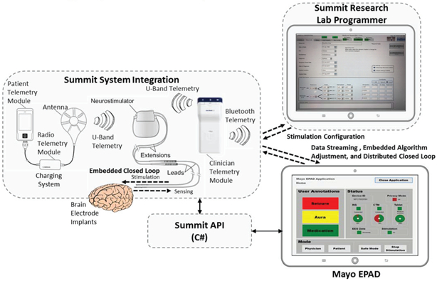
System level of the Summit™ RC+S system including integration of the application-programming-interface for configuring data streaming and algorithmic control of the device, using an example from the Mayo Clinic’s NIH BRAIN initiative program. The Research lab programmer configures the clinician limits for stimulation, and the patient telemetry modules and Epilepsy Personal Assistance Device (EPAD) allow for state monitoring and initiating fallback modes, all per 60601-1-10 guidelines.
IV. Summit Firmware and Software interfaces
This section discusses the firmware and software strategy for the Summit™ RC+S coprocessor architecture. Given the breadth of possible research studies that the Summit™ RC+S system will need to support, the software developed must provide the flexibility needed to implement experimental protocols. The configurable software of the system is broken into two main components –firmware embedded into the device, and a software package (the Summit API) that provides an abstracted command and control interface to develop applications that need to communicate with the implanted device. It is through the configuration and use of these two pieces of software, for embedded (on-INS) and distributed (on a connected Windows PC) computing respectively, that adaptive neuromodulation research can be performed in the clinic, home, or throughout a patient’s daily life.
The system block diagram is shown in Figure 9. At the center of the block diagram is the Summit™ INS, which interfaces to two external instruments – one for recharging the INS battery and the other (the Clinician Telemetry Module or CTM) as a telemetry bridge to a PC running an application developed with the Summit™ API. Two applications written with the Summit API are also shown in the Figure 9. The top application is the Summit Research Lab Programmer (RLP), which is a Medtronic-developed application that provides a clinical programming interface to set up safety “bounds” when performing adaptive stimulating research. To restrict the safety parameter configuration to Medtronic-controlled applications, the Summit™ RC+S system uses a proprietary authentication scheme that requires the application to prove it is a trustworthy (Medtronic-developed) entity to adjust the specific stimulation settings.
On a secondary computer (shown in the figure as the Mayo EPAD), investigators can develop their own applications using the documented functionality of the Summit™ API. The Summit API was developed in C# such that any Windows 7 or 10 based computer should be able to create and ran a custom Summit application through either Visual Studio or MATLAB. The API manages the bidirectional communication connection with the RC+S through the CTM and logs the data and results of all interactions with the INS to the computer’s filesystem in a known standardized format. Providing a standardized logging scheme reduces researcher burden for identifying and implementing their own logging methods (though they are of course able to log however they want in parallel with the API) and allows for the sharing of analysis tools across research sites. In addition, when not in session with an INS, the research software package also automates the upload of these logs to the secure Amazon Web Services database to enable the creation of large scale database creation for cross-study analysis of device performance, issue identification, and biomarker discovery.
Risk management was factored into the command structure. While all functions are available to call from a researcher-developed application, safety-related functions that require authentication will be rejected by the INS, restricting their use to just the RLP. However, all INS configuration outside of the safety settings are freely configurable from the user’s app. This includes the Summit™ RC+S configurations for the sensing, streaming, embedded 8-dimensional linear-SVM detector, stimulation adjustment (within the RLP-set bounds) and embedded algorithm settings. The linear SVM consists of 1 detector per sense channel. Each SVM allows for 2 power band inputs. This approach allows the development of iterative experiments, where sensing and algorithmic settings can be tested and evaluated sequentially, without constantly needing to swap instruments to adjust embedded settings that do not directly pose a risk to the subject. Any residual risk due to the specifics of stimulation and algorithms operating within safe clinician-set ‘bounds’ need to be independently accounted for by the clinicians and researchers themselves, including in-clinic validation, as they are accountable for their work done under an investigational device exemption. An expanded assessment of how the use of these devices for closed-loop research should be assessed for safety follows in the next sections.
V. Bench-Top and In-Vivo System Verification
Rigorous testing of the Summit™ RC+S neural coprocessor system is required to obtain regulatory approval for investigational studies. This begins with qualification of the integrated circuits and hybrid shown in Figure 3, and continues with system evaluation of electrical performance against IEC 60601-1/IS014708 and ANSI/AAMI PC69:2000 standards to show safety of the system to environmental aggressors such as external defibrillation events, electro-cautery use, and exposure to theft detection systems (EAS EM3801, Checkpoint, MT-5500, Sensormatic).
Verification of signal processing to close the loop can be achieved through multiple approaches. Given the multiple partitions available between hardware and firmware, each of these algorithmic methods was characterized. For example, signals may be streamed to an external computer for additional analysis of biomarkers using a computer-in-the-loop, such as the EPAD. The computer may use this information to provide meaningful feedback to the system in the form of change to stimulation parameters. Communication latency (<250mS max round-trip) was optimized to allow external algorithms to be assessed prior to embedding them chronically in the embedded system. The keys to achieving this round-trip latency lies in optimizing the micro-processor and MICS-band radio communication firmware with appropriate interrupt priority [29]. Once an external algorithm has been evaluated as successful, the embedded firmware can be configured through telemetry to evaluate subject benefit chronically.
The final system includes integration with leads and interconnections to complete the neural interface linkages. Bench top testing included characterization of sense-stim performance and recharge in a saline tank representing the biochemical enviromnent, as shown earlier during IC discussion.
VI. System Validation in a Representative Use-Case
Executing the in vivo protocols serve as a key validation step to ensure the capability of the system within the intended use cases. Using the complete prototype system, animal testing was conducted in ovine [24] and canine models [32] to generate 15 cumulative years of experience in representative use cases during the development process. The use-cases were chosen to exercise the flexibility of the Summit as a configurable neural co-processor, and ranged from brain interfaces for epilepsy, to distributed bladder control loops for incontinence, to responsive gastric stimulators; all testing protocols were reviewed and approved by Institutional Animal Use and Care Committees. We do an in-depth summary for the NIH epilepsy seizure prediction project as an example [29,32].
The Mayo Clinic is exploring a next-generation epilepsy management system utilizing the Summit RC+S and brain coprocessor concept as part of an investigational study for the NIH BRAIN initiative [32]. The epilepsy patient assistant device (EPAD) provides a flexible interface for patient interaction and analytics using data from wearable and implanted sensors and has bi-directional connectivity with the implanted neural stimulator. The next-generation epilepsy management system provides therapeutic electrical stimulation control policies driven by computationally efficient algorithms delivering fast response times embedded in the implanted device and computationally demanding algorithms implemented on the EPAD, or in the distributed cloud computing environments Figure 9.
The system provides responsive neural stimulation on 10-millisecond time scales using algorithms embedded in the implanted device. Algorithms for seizure forecasting [30] and behavioral state classification [31] are implemented on the EPAD. The EPAD tablet computer telemeters iEEG data as well as algorithm-derived and patient-initiated annotations over a conventional WiFi connection to a cloud computing enviromnent for remote data review and computationally intensive analysis. In summary, the system will provide a wireless, cloud-connected interface between patients and physicians and enable adaptive stimulation of neural networks with algorithms operating over time scales ranging from tens of milliseconds to months.
Preclinical testing of the epilepsy management system was performed in canines with naturally occurring epilepsy Figure 10 [32]. Epilepsy occurs naturally in dogs with prevalence, age of onset, and clinical presentation similar to human epilepsy [33], and dogs are large enough to accommodate devices designed for humans. The dogs are housed in groups, with 24/7 video monitoring, and continuous iEEG data telemetry. Nine dogs have been implanted and monitored, and the system has achieved a mean of 92% successful iEEG telemetry, excluding outages for system maintenance and recharging. The system has demonstrated successful on-device sensing in die Anterior Nucleus of Thalamus (ATN) and Hippocampus (HC) as well as responsive stimulation and on-tablet seizure forecasting, brain-state classification, and modulation of stimulation amplitude and frequency. An example of closed loop stimulation on detected epileptiform activity is shown in figure 11, and additional results can be found in [32].
Figure 10:
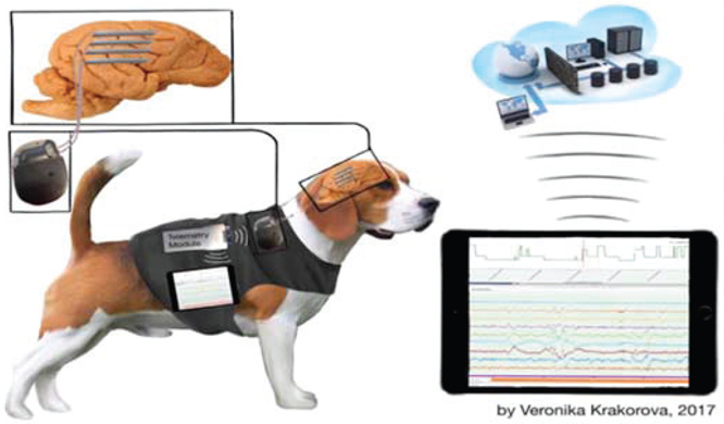
Illustration of brain coprocessor events from chronic brain recordings in-vivo: events are collected using the on-chip detection algorithms to trigger the detector when seizure-like activity is seen. [29, 32]
In summary, system validation protocol ensures that the neural coprocessor will meet the needs of the patient, clinician-investigator, and protocol aims. The example described here is part of a validation activity in preparation for human investigational study in epilepsy therapy, with an emphasis on the at-home application of Summit RC+S for seizure detection, prediction and prevention. Note that the reported validation steps are designed to prepare for the protocol; scientific results describing the therapeutic potential will be published in the future.
VII. Limitations of System Compared to State-of-Art
While the Summit™ RC+S system provides a fully implantable solution for enabling new adaptive DBS research, it is not the only research tool system intended for human neuromodulation research. A comparison of the Summit RC+S to other research tools [34-52] is captured in Table 4, which is an extension from the work in [52]. We highlight here a few key points relative to these systems.
Table 4:
Neural Research Tool System Comparison
| Attribute | Neurochip-2[39] | PennBMBI[40] | Toronto [41], [42],[43] (NURIP)f |
NeuroPace RNS[44], [45],[46] |
Activa PC+S[47], [48], [49], [50] |
WANDI[51] | Summit RC+S |
|---|---|---|---|---|---|---|---|
| Volume | 119 cm3 | 26 cm3 | 10.4 cm3 | 12.9 cm3 | 39 cm3 | 17.8 cm3 | 13.9 cm3 |
| Weight (total) | 145g, 204g* | --- | 12g | 16g | 67g | 18g | 29g |
| Power | 284-420mW | 290mW* | 45mW | ---- | 500uW* | 172mW | 2.5mW* |
| Hermetic/Fully Packaged | N | N | N | Y | Y | N | Y |
| Demonstrated IEC60601/14708 compliance | N | N | N | Y | Y | N | Y |
| Wireless Link | IR | Nordic-Enh Shockburst | ZigBee | 20-50kHz near-field inductive | 175kHz near-field inductive | Nordic BLE | MICS-band |
| Data Rate | -- | 2 Mbps | 250 kbps | - | 11.7 kbps | 2 Mbps | 195 kbps |
| Real-Time Streaming | No | 4 channels | 1 channel* | 1 channel | 2 channels time, 4 power | 96 channels+ +3-axis accel | 4 channels+ +3-axis accel |
| # Recording channels | 3 | 4 | 256 | 4 | 4 (mux from 8) | 128 | 4 (mux from 16) |
| Recording power/channel | -- | 1.25mW | 52uW (1.26uW) | --- | 5uW | 8uW | 5uW |
| Sampling Rate | 2/24 kS/s (24 on one channel) | 21 kS/s | 15 kS/s | 250 S/s | 422 S/s | 1 kS/s | 1kS/s |
| ADC resolution (bits) | 8 | 12 | 8 | 10 | 10 | 15 | 15 |
| Artifact Mitigation | Transient gain reduction | none | None (transient gain adjustment) | Lowpass fileter | Front-end filtering, heterodyning, symmetric sensing | Dynamic increase, memory-less sampling* | Dynamic range increase, synchronized blanking, clock management |
| Stimulation channels | 3 | 2 | 64 (32) | 8 | 8 | 128 (from 4 independent sinks/sources) | 16 with independent sinks/sources |
| Max current | 5 mA | 1 mA | 250 uA (3mA) | 11.5 mA | 25.5 mA | 5 mA | 25.5 mA |
| Compliance | +/−15V (50V*) | +/− 12V | 2.6 V (2.6V*) | 12 V | 15 V | 12 V | 15 V |
| Charge balance | Matching resistors (0.1%) | 0.75% mismatch | -- (binary exponential charge recovery) | < 10uC/sec charge imbalance | Passive discharge, DC blocking capacitor | Biphasic current source reuse (0.016% mismatch) | Passive discharge or programmable active recharge, DC blocking capacitor |
| Artifact cancellation | No | No | No (dynamic tracking) | No | Stimulation as input to SVM | Linear interpolation | Stimulation as input to SVM, time stamping |
| Biomarker detection (embedded) | Spectral power, action potential detection | Spectral power, time-domain features, action potential detection | Phase locking (band energy, phase locking value, cross frequency coupling) | ECoG signal intensity, line length, half-wave | Spectral power | Spectral power | Spectral power, posture and activity |
| Computer-in-loop latency (distributed algorithms) | N/A | --- | --- | N/A | <500 ms (allows for general algorithm off-device) | N/A | <100 ms (allows for general algorithm off-device) |
| Closed-loop Control policy | Detection/threshold-triggered | Detection/threshold-triggered | Threshold | Detection/threshold | 2D SVM | Threshold | 8D SVM, Threshold |
| Current Experimental subject | Non-human Primate | Rodent | Rodent | Human | Human | Non-human Primate | Human |
| Notes | *High compliance | *Estimated | *Estimated | *continuous streaming 24/7, *implies no DC blocking capacitor | *continuous streaming 24/7 |
Compared to many tools, the Summit™ RC+S system has limited channel count, most notably systems arising from the DARPA SUB-NETS and RAM programs [34], [35]. Yet as of this time, these systems are still in development and not yet available for chronic human use. Other than the Activa™ PC+S system, the most mature research systems that are actively in human trials are the Blackrock array and the Neuropace RNS. The Blackrock does have a significant advantage for channel count and bandwidth [36]. The current disadvantages of this system are its percutaneous connector block, and the lack of access to sub-cortical targets in the basal ganglia and thalamus, which are meaningful targets for many deep brain stimulation therapies. The RNS system from Neuropace is also a platform for clinical neuroscience work [37]. The advantage of this system is that it is commercially available, and the placement on the cranium helps eliminate artifacts from physiological sources. Relative drawbacks are the limited sensing during stimulation performance, which was disabled in the first commercial embodiment, and the use of primary cell battery technology. Even with these limitations, the RNS platform demonstrates the utility of a chronic sensing platform for understanding brain disease [37], [38].
A final limitation for investigators is our lack of directional electrodes in the current set of modular electrodes. The Summit™ RC+S system has a 2×8 connector port, however, which will allow for 1-3-3-1 style electrodes in the future. A potential drawback of this electrode is sensing during stimulation with measurement dipoles using imbalanced surface areas, which can potentially undermine the CMRR of the signal chain.
A key takeaway from Table 4 is that the Summit system represents the state-of-the-art for chronic human research systems, which require compliance to the essential requirements of EN 60601/IS014708 as an active implantable medical device, even when used as an investigational research tool. However, the table also suggests an emergent generation of systems, such as WAND [52] and NURIP [44], will continue to evolve and might eventually displace the Summit system.
A potential barrier for their adoption is power consumption. For example, today’s state-of-the-art rechargeable batteries of the size in Table 4 have on the order of 100mA-hr of capacity with roughly two volts of headroom. So for the WAND system, the estimated time between recharges is close to an hour -- roughly the same time as the recharge interval. This suggests that for high-channel-count, streaming systems, continuous power coupling might be the most likely system architecture unless other constraints like limiting channel count are applied.
From another perspective. Table 4 captures the dynamic evolution and roadmap of bi-directional neural interfacing, and the system architecture choices that must be made based on the desired application and user needs.
VIII. Conclusions
This work has introduced the design and preliminary validation of a neural coprocessor intended for exploring novel treatments for neurological disorders. The investigational device is currently being deployed as part of the BRAIN initiative, with targeted disease states spanning epilepsy, Parkinson’s disease, essential tremor, dystonia, obsessive compulsive disorder, and depression. In addition to the central nervous system, the system is being used for the exploration of dynamic stimulation in the periphery for incontinence, and for end-organ control in gastric disorders. The breadth of these disease states motivates a research tool design that uses modular, but standard, hardware that can be flexibly configured with software, much like a modem microprocessor. The hope is that insights gained from such systems, deployed in clinical investigational studies with subjects with the actual disease states, will help guide the development of future medical devices and therapies.
IX. Acknowledgments
This research was supported by Mayo Clinic Discovery Translation Grant, National Institutes of Health (R01 NS092882-03, UH2/UH3-NS95495) and institutional resources for research by Czech Technical University in Prague, Czech Republic.
X. References
- [1].Salanova Vicenta et al. “Long-term efficacy and safety of thalamic stimulation for drug-resistant partial epilepsy”, Neurology. 2015. March 10; 84(10): 1017–1025. [DOI] [PMC free article] [PubMed] [Google Scholar]
- [2].Perestelo-Pérez L, et al. “Deep brain stimulation in Parkinson’s disease: meta-analysis of randomized controlled trials. J Neurol 2014; February 2. [DOI] [PubMed] [Google Scholar]
- [3].Schuurman PR, et al. “A comparison of continuous thalamic stimulation and thalamotomy for suppression of severe tremor“ N Engl J Med 2000. February 17;342(7):461–8. [DOI] [PubMed] [Google Scholar]
- [4].Sprengers M et al. “Deep brain and cortical stimulation for epilepsy”, Cochrane Database Syst Rev 2017. July 18;7:CD008497. [DOI] [PMC free article] [PubMed] [Google Scholar]
- [5].Famm K et al. “Drug discovery: a jump-start for electroceuticals”, Nature. 2013. April 11;496(7444): 159–61. [DOI] [PMC free article] [PubMed] [Google Scholar]
- [6].Boyden E “Brain Coprocessors: The need for operating systems to help brains and machines work together. “ Intelligent Machines, Technology Review, September 22, 2010. [Google Scholar]
- [7].Grill WM et al. “Deep brain stimulation creates an informational lesion of the stimulated nucleus.”, Neuroreport. 2004. May 19; 15(7): 1137–40. [DOI] [PubMed] [Google Scholar]
- [8].Herron J et al. , "Cortical brain computer interface for closed-loop deep brain stimulation," IEEE Transactions on Neural Systems and Rehabilitation Engineering, vol. PP, no. 99. [DOI] [PubMed] [Google Scholar]
- [9].Opri E, Cemera SL, Okun MS, Foote KD, Gunduz A, “Towards adaptive cortico-thalamic closed-loop deep brain stimulation for the treatment of essential tremor,” Neuroscience Annual Meeting, 389.17/Y17, Washington, DC, 2017. [Google Scholar]
- [10].Swann Nicole et al. “Chronic multisite brain recordings from a totally implantable bidirectional neural interface: experience in five patients with Parkinson’s disease”, J Neurosurg 2018. February;128(2):605–616. doi: 10.3171/2016.11.JNS161162. Epub 2017 Apr 14. [DOI] [PMC free article] [PubMed] [Google Scholar]
- [11].Herron Jeffery A. et al. “Chronic electrocorticography for sensing movement intention and closed-loop deep brain stimulation with wearable sensors in an essential tremor patient,” Journal of Neurosurgery September 2017/Vol. 127 / No. 3 / Pages 580–587. [DOI] [PubMed] [Google Scholar]
- [12].Arlotti M et al. “Eight-hours adaptive deep brain stimulation in patients with Parkinson disease”, Neurology. 2018. March 13;90(11):e971–e976. [DOI] [PMC free article] [PubMed] [Google Scholar]
- [13].Shute Jonathan B., “Thalamocortical network activity enables chronic tic detection in humans with Tourette syndrome”, Neuroimage Clin 2016; 12: 165–172. [DOI] [PMC free article] [PubMed] [Google Scholar]
- [14].Majerus Steve et al. , “Wireless bladder pressure monitor for closed-loop bladder neuromodulation,' 2016 IEEE SENSORS, Orlando, FL, 2016, pp.1–3. [DOI] [PMC free article] [PubMed] [Google Scholar]
- [15].Wenzel BJ, “Closed loop electrical control of urinary continence”, J Urol 2006. April; 175(4): 1559–63. [DOI] [PubMed] [Google Scholar]
- [16].Stanslaski Scott et al. “Design and Validation of a Fully Implantable, Chronic, Closed-loop Neuromodulation Device with Concurrent Sensing and Stimulation”, IEEE Trans Neural Syst Rehabil Eng 2012. July;20(4):410–21. doi: 10.1109/TNSRE.2012.2183617. Epub 2012 Jan 23. [DOI] [PubMed] [Google Scholar]
- [17].IEC 60601-1-10:2007, International Organization of Standards (ISO).
- [18].Kupsch A, Benecke R, et al. “Pallidal Deep-Brain Stimulation in Primary Generalized or Segmental Dystonia” N Engl J Med 2006;355:1978–1990. [DOI] [PubMed] [Google Scholar]
- [19].Stypulkowski PH, Stanslaski SR, Denison TJ, Giftakis JE. “Chronic evaluation of a clinical system for deep brain stimulation and recording of neural network activity.” Stereotact Fund Neurosurg. 2013;91(4): 220–32. [DOI] [PubMed] [Google Scholar]
- [20].Swann Nicole C et al. , “Adaptive deep brain stimulation for Parkinson’s disease using motor cortex sensing”, 2018. J. Neural Eng 15 046006. [DOI] [PMC free article] [PubMed] [Google Scholar]
- [21].Afshar Pedram, “A translational platform for prototyping closed-loop neuromodulation systems”, 2013 Fronteirs in Neural Circuits 22 January 2013. [DOI] [PMC free article] [PubMed] [Google Scholar]
- [22].Khanna P et al. , “Demonstration: Enabling closed-loop neurostimulation with downloadable firmware upgrades,' 2015 IEEE Biomedical Circuits and Systems Conference (BioCAS), Atlanta, GA, 2015, pp. 1–1. [Google Scholar]
- [23].Sooksood K et al. “An experimental study on passive charge balancing”, Adv. Radio Sci, 7, 197–200, 2009. [Google Scholar]
- [24].Stypulkowski P et al. “Modulation of hippocampal activity with fornix Deep Brain Stimulation” Brain Stimulation 2017. 1–8. [DOI] [PubMed] [Google Scholar]
- [25].Cong Peng et al. , “A 32-Channel Modular Bi-directional Neural Interface System with Embedded DSP for Closed-Loop Operation” ESSCIRC 2014 - 40th European Solid State Circuits Conference (ESSCIRC) [Google Scholar]
- [26].Herron J, Stanslaski S, Chouinard T, Corey R, Orser H, Denison T “Bi-directional brain interfacing instrumentation”, 2018 IEEE International Instrumentation & Measurement Technology Conference (I2MTC), Houston, USA, May 2018. [Google Scholar]
- [27].Shute Jonathan B et al. “Thalamocortical network activity enables chronic tic detection in humans with Tourette syndrome”, Neuroimage Clin 2016. June 25; 12:165–72. [DOI] [PMC free article] [PubMed] [Google Scholar]
- [28].Christopher Davies et al. , “Evaluation of an innovative spinal cord stimulator platform for the treatment of chronic pain” Pain Management 10.2217/pmt-2017-0073 C 2018. FutureMedicineLtd. [DOI] [PubMed] [Google Scholar]
- [29].V Klemen et al. “Continuous active probing and modulation of neural networks with a wireless implantable system” IEEE BioCAS 2017. (in press). [Google Scholar]
- [30].Brinkmann BH et al. , “Crowdsourcing reproducible seizure forecasting in human and canine epilepsy.” Brain 139, 1713–1722 [DOI] [PMC free article] [PubMed] [Google Scholar]
- [31].Kremen V et al. , “Behavioral state classification in epileptic brain using intracranial electrophysiology.” J Neural Eng 14, 026001. [DOI] [PMC free article] [PubMed] [Google Scholar]
- [32].Vaclav Kremen et al. “Integrating Brain Implants with Local and Distributed Computing Devices: A Next Generation Epilepsy Management System.” IEEE JTEHM, (This article has been accepted for publication in a future issue of this journal, but has not been fully edited. Citation information: DOI 10.1109/JTEHM.2018.2869398, IEEE Journal of Translational Engineering in Health and Medicine) [DOI] [PMC free article] [PubMed] [Google Scholar]
- [33].Berendt M, Gram L, “Epilepsy and seizure classification in 63 dogs: a reappraisal of veterinary epilepsy terminology.” J Vet Intern Med, 13(1): 14–20. [PubMed] [Google Scholar]
- [34].Muller Rikky et al. “A 0.013 mm 2, 5 μW, DC-Coupled Neural Signal Acquisition IC With 0.5 V Supply”IEEE Journal of Solid-State Circuits Volume: 47, Issue: 1, Jan. 2012. [Google Scholar]
- [35].Muller Rikky et al. “A Minimally Invasive 64-Channel Wireless μECoG Implant” IEEE Journal of Solid-State Circuits Volume: 50, Issue: 1, Jan. 2015. [Google Scholar]
- [36].Yin Ming et al. “A 100-Channel Hermetically Sealed Implantable Device for Chronic Wireless Neurosensing Applications”, IEEE Transactions on Biomedical Circuits and Systems Volume: 7, Issue: 2, April 2013. [DOI] [PMC free article] [PubMed] [Google Scholar]
- [37].Sun Felice T. et al. “Responsive cortical stimulation for the treatment of epilepsy”, Neurotherapeutics. 2008. January; 5(1): 68–74. [DOI] [PMC free article] [PubMed] [Google Scholar]
- [38].Chan Alvin Y. et al. “Seizure localization by chronic ambulatory electrocorticography”, Clinical Neurophysiology Practice, 25 April 2018. [DOI] [PMC free article] [PubMed] [Google Scholar]
- [39].Zanos S, Richardson AG, Shupe L, Miles FP & Fetz EE The Neurochip-2: An Autonomous Head-Fixed Computer for Recording and Stimulating in Freely Behaving Monkeys. IEEE Trans. Neural Syst. Rehabil. Eng 19, 427–435 (2011) [DOI] [PMC free article] [PubMed] [Google Scholar]
- [40].Liu X et al. The PennBMBI: A general purpose wireless Brain-Machine-Brain Interface system for unrestrained animals. in 2014 IEEE International Symposium on Circuits and Systems (ISCAS) 650–653 (IEEE, 2014). doi: 10.1109/ISCAS.2014.6865219 [DOI] [Google Scholar]
- [41].Bagheri A et al. Massively-Parallel Neuromonitoring and Neurostimulation Rodent Headset With Nanotextured Flexible Microelectrodes. IEEE Trans. Biomed. Circuits Syst 7, 601–609 (2013). [DOI] [PubMed] [Google Scholar]
- [42].Shulyzki R et al. 320-Channel Active Probe for High-Resolution Neuromonitoring and Responsive Neurostimulation. IEEE Trans. Biomed. Circuits Syst 9, 34–49 (2015). [DOI] [PubMed] [Google Scholar]
- [43].Salam MT, Perez Velazquez JL & Genov R Seizure Suppression Efficacy of Closed-Loop Versus Open-Loop Deep Brain Stimulation in a Rodent Model of Epilepsy. IEEE Trans. Neural Syst. Rehabil. Eng 24, 710–719 (2016). [DOI] [PubMed] [Google Scholar]
- [44].O’Leary G et al. , A Recursive-Memory Brain-State Classifier with 32-Channel Track-and-Zoom Delta-squared-Sigma ADCs and Charge-Balanced Programmable Waveform Neurostimulators. IEEE International Solid-State Circuits Conference (2018). [Google Scholar]
- [45].NeuroPace RNS System User Manual. (2015).
- [46].NeuroPace NIH Collaborative Research Agreement - Company Materials.
- [47].Thomas GP & Jobst BC Critical review of the responsive neurostimulator system for epilepsy. Medical Devices: Evidence and Research 8, 405–411 (2015). [DOI] [PMC free article] [PubMed] [Google Scholar]
- [48].Stanslaski S et al. Design and Validation of a Fully Implantable, Chronic, Closed-Loop Neuromodulation Device With Concurrent Sensing and Stimulation. IEEE Trans. Neural Syst. Rehabil. Eng 20, 410–421 (2012) [DOI] [PubMed] [Google Scholar]
- [49].Rouse AG et al. A chronic generalized bi-directional brain-machine interface. J. Neural Eng 8, 36018 (2011). [DOI] [PMC free article] [PubMed] [Google Scholar]
- [50].Avestruz A-T et al. A 5 μW/Channel Spectral Analysis IC for Chronic Bidirectional Brain– Machine Interfaces. IEEE J. Solid-State Circuits 43, 3006–3024 (2008). [Google Scholar]
- [51].Lempka SF, Howell B, Gunalan K, Machado AG & McIntyre CC Characterization of the stimulus waveforms generated by implantable pulse generators for deep brain stimulation. Clin. Neurophysiol 129, 731–742 (2018). [DOI] [PMC free article] [PubMed] [Google Scholar]
- [52].Zhou* AJ, Santacruz* SR, Johnson* BC, Alexandrov GP, Moin A, Burghardt FL, Rabaey JM, Carmena JM, Muller R, “WAND: A 128-channel closed-loop, wireless, artifact-free neuromodulation device” arXiv: 1708.00556 [DOI] [PubMed] [Google Scholar]