

Abstract
Experimentally accessible tools to replicate the complex biological events of in vivo organs offer the potential to reveal mechanisms of disease and potential routes to therapy. In particular, models of inter-organ communication are emerging as the next essential step towards creating a body-on-a-chip, and may be particularly useful for poorly understood processes such as tumor immunity. In this paper, we report the first multi-compartment microfluidic chip that continuously recirculates a small volume of media through two ex-vivo tissue samples to support inter-organ cross-talk via secreted factors. To test on-chip communication, protein release and capture were quantified using well-defined artificial tissue samples and model proteins. Proteins released by one sample were transferred to the downstream reservoir and detectable in the downstream sample. Next, the chip was applied to model the communication between a tumor and a lymph node, to test whether on-chip dual-organ culture could recreate key features of tumor-induced immune suppression. Slices of murine lymph node were co-cultured with tumor or healthy tissue on-chip with recirculating media, then tested for their ability to respond to T cell stimulation. Interestingly, lymph node slices co-cultured with tumor slices appeared more immunosuppressed than those co-cultured with healthy tissue, suggesting that the chip may successfully model some features of tumor-immune interaction. In conclusion, this new microfluidic system provides on-chip co-culture of pairs of tissue slices under continuous recirculating flow, and has the potential to model complex inter-organ communication ex vivo with full experimental accessibility of the tissues and their media.
Keywords: organ-on-chip, recirculation, transverse perfusion, cancer immunology, immunosuppression, IFN-γ
Graphical Abstract
The first microfluidic device for co-culture of two tissue slices under continuous recirculating flow was used to model tumor-induced immunosuppression.
Introduction
With proper selection of materials and careful design, microfluidic chips can provide a biomimetic environment for cell and tissue culture, maintaining key aspects of the biological system while integrating with downstream analysis.1,2 Microfluidic devices are increasingly used to replicate complex physiological events such as angiogenesis3 and tumor metastasis.4 Researchers have applied microfluidics to mimic in vivo organs, either through sophisticated co-cultures of cells, so-called “organs on chips,”5 or, more rarely, through ex vivo culture of intact tissue samples.6 However, replicating the interactions between multiple organs remains a grand challenge for microfluidics and bioengineering.
In vivo, organs are connected via networks of blood vessels and lymphatic vessels and communicate via signaling molecules, exosomes, and cells transported between them. Initial, pioneering bioengineered systems necessarily focused on modeling a single tissue, such as a lung, gut, or tumor.5–7 Such systems provide an excellent model of cell behavior within one compartment or microenvironment, and additional functionality may be incorporated by adding other cells (e.g. immune cells) directly into the compartment8 or into an adjacent region representing the vasculature.9,10 In order to study the effects of communication between organs, however, multiple tissue environments are required.11,12 In vivo, it is challenging to isolate the interactions between just two organs, because they are embedded within the complex whole-body environment; signals released by each organ are quickly diluted into the bloodstream and delivered to many other tissues. In response, researchers have generated microfluidic systems to directly study the interactions between multiple compartments or organs.13 Strategies used to connect compartments range from diffusion alone,14,15 analogous to a standard Transwell system, unidirectional flow to carry signals from one compartment to the next, with or without pumps,16–18 reciprocating recirculation achieved by rocking the device back and forth,13 and continuously recirculating flow using off-chip or on-chip pumps or innovative gravity-driven flow configurations.19–22
So far, multi-organ models have been developed primarily from cell cultures or organoids; systems to culture and connect live ex vivo tissue samples are less common than their cell-based counterparts.6,23 Ex vivo tissue slices offer a unique intermediate between cell cultures or organoids and in vivo experimentation. Slices preserve the physiological architecture of the extracellular matrix and the native organization of cells, while making the tissue more experimentally accessible for stimulation and imaging than it is in vivo.24–28 Combining the advantages of tissue slices with microfluidics has offered the opportunity to maintain perfusion cultures and control local microenvironments.2,6,29–36 Furthermore, clever integration of multiple ex vivo tissues into a microfluidic device, though still rare, may reveal interactions between the two samples and may improve the similarity to in vivo models for mechanistic studies, drug screening, and toxicity screening.16,20 We speculate that such tools may be especially useful for organ systems whose interactions are critical to disease but poorly understood, such as tumors and lymph nodes.
Tumor immunity is emerging as a potential path to cancer therapy, but new tools are needed to model the complexity of this system. Existing microfluidic models of tumor immunity have focused primarily on events in the tumor or the nearby vasculature.37–39 However, tumor development and survival are thought to be a function of the balance of anti-tumor immunity and immune tolerance in neighboring lymph nodes.40 The lymph nodes nearest to a tumor, called tumor-draining lymph nodes (TDLNs), are profoundly altered in terms of function.41,42 In some cases, immune cells in these lymph nodes appear tolerized to tumor cells or even exhausted, unable to respond normally to non-specific stimulation.43,44 It is not clear how far such suppression spreads through the lymphatic network over time, nor the extent to which suppression spreads through secreted factors.42
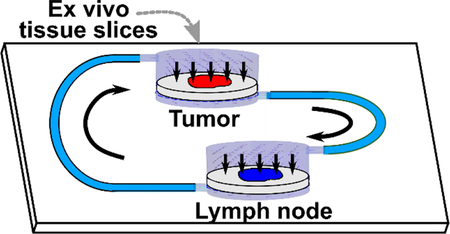
Here, as a first step towards modeling this two-compartment system, we developed a two-chamber microfluidic device with continuously recirculating flow to transport secreted signals between tissue slices. Rather than recreate the complex connections via blood and lymphatic vessels that connect the tumor and TDLNs in vivo (Figure 1a), we simplified to a single loop representing lymphatic drainage from tumor to TDLN and blood flow from TDLN to tumor (Figure 1b). To avoid dilution of signals at low concentrations, a minimal volume of media was recirculated, and perfusion through, rather than over, the tissue was used to ensure access to the center of these thick tissue samples.30,45 We validated circulation of proteins in the chip, confirmed viability of tissues after on-chip culture, and finally investigated the impact of tumor-lymph node interactions on lymph node immunosuppression. This device is the first to provide continuous recirculating flow of small volumes between two tissue slices. Furthermore, this is the first demonstration of signaling cross-talk between tumor and lymph node slices on-chip.
Figure 1.

Modeling tumor-lymph node interactions on a dual-slice microfluidic chip with continuous recirculating flow. (a) In vivo, tumors and lymph nodes communicate via lymphatic fluid drainage from the tumor to lymph node, and via blood flow that carries signals and cells from the lymph node back to the tumor. (b, c) A simplified conceptual schematic (b, top view; c, side view of tissue chamber) of the dual-slice chip. Arrows indicate the direction of fluid flow. The tissue sample rests on a track-etched membrane, and flow passes through it on the way to the next chamber.
Experimental
Device fabrication and assembly
Preparing layers:
The device consisted of two culture wells, each 3-mm in diameter and 1200-μm deep in total, two reservoirs 5-mm in diameter and 5-mm deep, and microchannels 500-μm wide, 200-μm deep and ~80-mm long. The external dimension of the assembled device was 50 mm × 25 mm, designed to fit on a standard microscope slide. The chip was constructed from three layers of polydimethylsiloxane (PDMS), each patterned on an SU-8 master, and one polycarbonate membrane (also called “track-etched membrane”, Sterlitech, Cat# PCT2047100, WA, USA) (Figure 2a). The masters were produced using conventional photolithographic fabrication of SU-8 features on silicon wafers, as previously described.46 CAD files and details of fabrication are provided in the SI.
Figure 2.

Device fabrication and operation. (a) 3D rendering of the three layers of the device, drawn to scale. The top and lower layers were made of PDMS with 200-μm feature depth, and the middle layer was a 1-mm thick PDMS membrane. A 10-μm thick track-etched polycarbonate membrane, shown atop the lower layer, was fixed in place using PDMS glue. Insets show enlarged diagrams of (i) the top portion of a culture well, and (ii) a reservoir, and (iii) the lower portion of a culture well, located below the polycarbonate membrane. (b) 3D schematic of the assembled device with tubing inserted into the access ports. The culture wells, reservoirs, connections for peristaltic pumps, and air vents are labelled. (c) Photo of the assembled device, shown without binder clips for clarity. A rigid polymethyl methacrylate (PMMA) cover is placed over the top PDMS layer for mechanical support; the cover was omitted in panels a-b for clarity. (d) The flow path for recirculating fluid flow, overlaid onto the same schematic as in (b). The two colors (blue, purple) indicate flow through each half of the chip; the color changes at the point where fluid passes through the tissue in the culture well. (e) The flow path when the chip is viewed from the top, shown without tubing for clarity.
Sterilizing components:
Prior to assembly, all PDMS layers and tubing were soaked in 70% ethanol for 10 min and rinsed for more than 10 minutes with MilliQ ultra-pure water. Each piece was then dried in a 60 °C oven inside sterile plastic petri-dishes. To sterilize the track-etched membrane, the assembled bottom part was filled with 70% ethanol for 10 min and rinsed with MilliQ water in a laminar flow biosafety cabinet.
Assembling bottom part:
To construct the bottom part of the chip, a 2-μm pore-size track-etched membrane was cut into an 8-mm wide strip and glued into position between the PDMS membrane (1 mm thick) and lower PDMS piece (200 μm feature depth). The gluing agent was prepared by mixing PDMS mix (PDMS: curing agent=10:1 mass ratio) and toluene at 1:1 mass ratio, and the glue was spun to ~10 μm thick on a clean, bare 3-inch silicon wafer at 2000 rpm. The surfaces of the two PDMS layers were assembled with this glue; careful handling was used to prevent blocking of the microchannels. The assembly was sandwiched by two clean standard glass slides, clamped with a binder clip, and cured in a 60 °C oven overnight.
Coating with bovine serum albumin:
To reduce nonspecific binding of proteins to the surface of the tubing and microchannels, the device was blocked with 1% bovine serum albumin (BSA: Cat#: BP9704–100, Fisher Scientific, Fair Lawn, JN, USA). A 1 % BSA solution in 1x Dulbecco’s Phosphate Buffered Saline without calcium or magnesium (1x PBS, Lonza, Cat# 17–512F) was degassed for 10 min before use. Degassed BSA solution was injected into to the bottom channel via the air removal port, and droplets of BSA solution were pipetted onto to the open face of the culture wells and microchannels of the top layer. The device was incubated with BSA for 30 min at room temperature before further assembly.
Device assembly with tissue:
The top and bottom parts of the chip were exposed to UV light for 30 min in a biosafety hood to sterilize the inside faces of the chip. With a clean fan brush, slices of agarose or tissue (3 mm diameter) were transferred onto the open culture wells in the bottom part of the chip. The device was assembled by aligning the top and bottom, inserting PTFE tubing (Figure 2b), and adding a rigid polymethyl methacrylate (PMMA) cover on the top and a clean glass slide on the bottom for rigidity (Figure 2c). The tubing was 0.012” i.d., 0.009” wall (TT-30, from Weico Wire & Cable Inc, Edgewood, NY). The PMMA cover was prepared by laser etching (Versa Laser 3.5, Universal Laser Systems, Scottsdale AZ, USA) to accommodate insertion of tubing and provide access to open reservoirs (CAD file provided in SI). The assembly was clamped together with binder clips. Immediately after assembly, the device was filled with complete media (RPMI-1640 (Lonza, Cat# 12–918F) supplemented with 10% FBS, 1% L-glutamine, 1% Pen/Strep, 50 μM 2-Mercaptorethanol, 1 mM Pyruvate, 1% Non-Essential Amino Acids, and 20 mM HEPES). The device was connected to a syringe pump (Fusion 710, Stafford, TX, USA) or a peristaltic pump (BT100–1F-B, Langer Instruments, Boonton, NJ, USA) via sterile tubing. Media was perfused unidirectionally through the microchannels and tubing (Figure 2d and e). The whole system ran in a 37 °C incubator with 5% CO2 unless otherwise noted.
Simulation of fluid flow on-chip
The flow profile through the tissue loaded-culture well was modeled in three dimensions using the Free and Porous Media Flow module of COMSOL Multiphysics 5.2. The simulated culture well was specified as a cylinder, 3 mm in diameter and 1 mm deep, containing 300 μm-thick tissue and a 10 μm track-etched membrane near the bottom. A 200-μm inlet was located on the upper side of the tissue upper chamber, and a 200-μm outlet was located on the lower side of the membrane opposite the chamber. The inlet flow rate was set to 2 μL/min. The outlet was set to atmospheric pressure. Aqueous media was modeled as an incompressible fluid with density 1000 kg/m3 and viscosity 1.00 mPa s. The tissue was modeled as a porous matrix with the Darcy permeability set to 3 × 10⁻¹² m2 (See SI Methods).34 A 10 μm-deep region representing the track-etch membrane was included beneath the tissue. The track-etched membrane was modeled as a porous matrix with porosity of 0.06 [unitless] and permeability of 7.25 × 10⁻¹⁴ m2, based on the manufacturer’s specification for the membrane used in experiments. Additionally, where noted, a 100-μm gap was included between the tissue region and the walls of the chamber (Figure S2). A “fine” triangular mesh was used as generated by the software. The simulation was solved in time-dependent mode, and results were arbitrarily reported for 30 min. The flow profile reached a steady state after 1–2 min.
Testing protein release and capture individually on-chip
To test protein release and capture independently, we used a half configuration of the chip by disconnecting the tubing between the two culture wells. This allowed for one-way perfusion through each culture well separately. 6% low melting point agarose (Lonza, cat# 50080, Walkersville MD, USA) was heated, cast into a dish, cured at room temperature, and cut into blocks. The agarose block was sliced on a vibratome (Leica VT1000s, Bannockburn IL, USA) according to published protocols36,46 and punched with a 2-mm-diameter biopsy punch.
Protein release test:
To generate a protein-loaded model tissue, a 300-μm thick agarose slice was equilibrated with 1.7 μg/mL avidin-HRP (Cat# 21123, Thermo Fisher Scientific, USA) in 1% BSA buffer overnight and then was loaded into the culture well on-chip. Next, 1% BSA buffer was perfused via syringe pump at 0.5 μL/min for 2 hours at room temperature. The supernatant was collected from the downstream reservoir, analyzed by adding substrate (BD TMB Substrate Reagent Set, Cat# BD 555214, Thermo Fisher Scientific, USA), then quenched by adding 1 M H2SO4. Absorbance was read using a plate reader and compared to a calibration curve to calculate the mass of HRP in the sample.
Protein capture test:
To generate a model tissue capable of capturing protein, biotinylated beads were embedded in agarose by mixing 10 μL of 5 mg/ml biotinylated beads (TM-10–10, Sphero™, 1.0 μm, Spherotech Inc., Lake Forest IL, USA) with 90 μL of heated 6% agarose and curing the mixture in a PDMS well, 5-mm in diameter and 4-mm high. The cured block was sliced into 300-μm thick sections by a vibratome, and a slice was loaded into the culture well on-chip. Bead-slices were perfused with 60 μL NeutrAvidin-Rhodamine Red-X at 5 μg/mL (Cat#: A6378, ThermoFisher Scientific, USA) via syringe pump at 0.5 μL/min for 2 hours at room temperature. The slice was collected from the chip, transferred to a well plate containing 1x PBS, imaged on a Zeiss Axio Zoom macroscope (Carl Zeiss Microscopy, Germany), and analyzed by ImageJ. The background subtracted mean fluorescent intensity was calculated as described in SI Methods.
Testing communication between two samples on-chip
To test protein release and capture between slices under continuous recirculation, the full configuration of the chip was used in which the two culture wells and reservoirs were interconnected via microchannnels, tubing, and two peristaltic pumps. To release the total protein mass of 0.3 μg, a protein-loaded agarose slice (volume ~ 1 μL) was generated by equilibrating with 0.3 μg/μl Neutravidin-Rhodamine Red-X and was loaded into the first culture well (top red circle, Figure 4a). A bead-laded slice was prepared as described above and loaded into the second culture well (black-dotted green circle, bottom culture well in Figure 5a). Each slice was imaged in a well plate prior to initiating media flow. 1% BSA buffer was perfused at 0.5 μL/min for 24 hours at 37 °C. The slices were collected from the chip, imaged again, and analyzed as previously described.
Figure 4.

Protein release from and capture in agarose slices on a chip. (a) Avidin-HRP (red, av-HRP) was pre-soaked into an agarose slice and perfused. (b) After 2 hours, an aliquot was collected from the downstream reservoir. (c) The quantity released was similar in a microwell plate as on the chip, as quantified by reaction with a colorimetric substrate for HRP (TMB substrate) (N = 4). (d) NRho (red) was flowed on-chip through an agarose slice (green) prepared with or without biotin-functionalized beads (black dots). (e) After two hours, captured protein was visualized by fluorescence microscopy. (f) A high fluorescent intensity was observed in slices with beads but not without beads, showing specific protein capture (N = 3). Bars show mean and standard deviation. Each dot indicates one trial of the experiment. NS indicates no significant difference and * indicates p-value < 0.05, as determined by one-way ANOVA. The chip schematics were not drawn to scale.
Figure 5.

Demonstrating dual-slice protein communication. (a) Experimental setup: one slice was presoaked in NRho (red dot in schematic) and the other was loaded with biotinylated beads (green dot in schematic). Initially, the protein-loaded slice showed strong but diffusing red color under fluorescent microscopy (top image), and the bead-laden slice appeared dark (lower image). (b) Quantification of fluorescent intensity at t = 0. (c) Results after 24 hours continuous perfusion: the presoaked proteins were undetectable in the first slice (top fluorescent image) and had been captured by the other, bead-laden slice (lower image) (d) Quantification of fluorescent intensity at t = 24 hours. Comparing b and d, most of the protein was transferred between the two slices. Bars show mean and standard deviation; n = 4. **** indicates p-value < 0.0001 by one-way ANOVA. The chip schematics were not drawn to scale.
Animal model
All animal work was approved by the Institutional Animal Care and Use Committee at the University of Virginia under protocol #4042, and was conducted in compliance with guidelines from the Office of Laboratory Animal Welfare at the National Institutes of Health (United States). Female Balb/c mice were purchased from Jackson Laboratories (USA) and used while aged 6–12 weeks. Mice were housed in a vivarium and provided with food and water ad libitum. 250,000 4T1-dsred-luc cells were suspended in phosphate-buffered saline (PBS) with 3 mg/ml growth-factor reduced Matrigel (Cultrex PathClear 3-D Culture Matrix RGF BME, R&D Systems, Minneapolis MN, USA), at a concentration of 5×10⁶ cells/mL. This mixture (50 μL) was injected sub-areolarly into the right 4th mammary fat pad (inguinal). Tumors were allowed to grow for 7 days, after which mice were anesthetized with isoflurane and immediately euthanized by cervical dislocation. Tumors, contralateral fat pads, and the inguinal, axillary, and brachial lymph nodes from both sides were collected. For simplicity, the three lymph nodes from the same side as the tumor were combined and considered “tumor-draining lymph nodes” (TDLN) and those from the contralateral side were considered “non-draining lymph nodes” (NDLN). Thus, any differences between the inguinal, axial, and brachial nodes were not detected. For naïve controls, the inguinal fat pad was collected along with the six mentioned lymph nodes from healthy, non-tumor bearing mice.
Preparing tissue slices
Lymph nodes were sliced as described previously with a few small adjustments.36,46 Briefly, lymph nodes were embedded in 6% low-melting point agarose and sliced to 300-μm on a vibratome inside a biosafety cabinet (Speed scale value: 3.9 (0.17 mm/s), Frequency scale value: 1 (~10 Hz)). Slices were collected in sterile 1x PBS containing 1% Penicillin/Streptomycin (Fisher Scientific) and immediately transferred to a well-plate containing complete media. These slicing conditions preserve lymph node tissue viability without detectable inflammation for at least 24 hr (manuscript in preparation). Tumors were first manually sectioned into ~2 mm diameter pieces using a sterile razor and then embedded in 6% low-melting point agarose and sliced to 300-μm on a vibratome using the same procedure as for lymph nodes. This thickness is optimal for preserving the viability of tumor slices.33,47 Due to the technical challenge of slicing fat, the fat pads were manually sectioned into ~2 mm diameter pieces with a razor blade and not sliced; when used on the chip, they were spread flat onto the floor of the culture well, ~1 mm thick. All tissue samples were allowed to rest in complete media in a cell culture incubator (37 °C, 5% CO2) for at least 1 hour before further experimentation. Tissue viability was measured using Calcein AM staining (SI Methods).
Off-chip analysis of tumor cell invasion and T cell activity
Quantifying in vivo tumor cell invasion:
To investigate tumor cell dissemination to lymph nodes in vivo, slices of tumor, TDLN, NDLN, and naïve lymph node were fixed in formalin (4% paraformaldehyde), stored in 1x PBS at 4°C. The tissues were imaged on a Zeiss Axio Zoom Macroscope to visualize dsRed signal from tumor cells, using a Rhodamine filter set (Zeiss filter set #43, excitation wavelength: 550/25 nm, emission wavelength: 605/70 nm). Images were analyzed by ImageJ (SI Methods).
Testing T cell activity in lymph node slices:
Lymph node slices were cultured in 500 μL complete media containing 0.5 μg/mL soluble anti-CD3ɛ (clone: 145–2C11, Biolegend, Cat#100331, San Diego, CA, USA) for 24 hours. The supernatant was collected, frozen at −80 °C, and later tested for IFN-γ concentration by ELISA (SI Methods). Because cytokine secretion is expected to depend on the number of cells in the tissue, IFN-γ secretion was normalized by dividing by the tissue area. Tissue area was quantified by imaging the slices and analyzing in ImageJ.
On-chip co-culture of tissue slices
To test a model of tumor immunity, a slice of NDLN and either a slice of tumor or a section of fat pad was each loaded into a culture well on-chip as described above. The chip and pumps were placed in a sterile culture incubator (37 °C, 5% CO2), and the tissues were continuously perfused with media at 2 μL/min for 24 hours. Afterwards, lymph node slices were collected, imaged, and tested for T cell activity as described above. Where noted, 50 ng/mL interleukin-2 (Murine IL-2, Peprotech, Cat#212-12-50UG, NJ, USA) was added to the culture media during on-chip and off-chip culture.
Results and Discussion
Device design and use for recirculating fluid flow
To support two-way communication between a pair of living tissue samples, we first considered whether diffusion or flow should be the primary means of inter-organ transport on the microfluidic chip. Standard in vitro co-culture methods for cells and tissues, such as Transwell inserts and membrane-based two-chamber organ-on-chip devices, rely on diffusion to relay secreted signals such as proteins and small molecules from one sample to the other. However, communication by diffusion is slow: for a typical protein with aqueous diffusion coefficient D ~ 10−11 m2/s, the average time, tD, to diffuse a distance (x) of 200 μm or 2 mm is ~ 30 min or > 2 days, respectively (tD = x2/2D). Instead of diffusion, we used recirculating fluid flow that passed through each tissue sample in turn. This strategy enabled the tissue samples to be spaced more than a few millimeters apart and still retain bidirectional communication. Compared to a stacked system, spacing out the samples laterally simplifies imaging of each tissue and the channel between them during the experiment, and offers the potential to integrate more than two tissue samples in future versions of the chip.19
To achieve continuous recirculating flow on the microfluidic chip, we utilized two off-chip peristaltic pumps, selected for their minimal stroke volume, and connected these in-line with the two culture chambers and two reservoirs for sample collection (Figure 3a). A semi-permeable membrane (2-μm pore size) beneath the culture wells supported the tissue slices and inhibited cell migration into the channel. The two reservoirs were open to ambient air to allow gas exchange, and they also provided access to the culture supernatant for collection during the experiment. To assemble the chip, a tissue slice was loaded into each culture well, and the top and bottom layers were clamped together. After connecting pumps, filling the channels with culture media, and closing the air vents, the whole system was placed in a cell incubator for culture, and flow was initiated (Figure 2d and e). Media recirculated through the microchannels unidirectionally (Figure 2d and e), which each pump withdrawing media downstream of one culture chamber and infusing it upstream of the next one.
Figure 3.

Design of the dual slice chip. (a) Top view schematic to illustrate the design. The chip houses two culture wells for tissue slices (green) and two open reservoirs, with two in-line peristaltic pumps (yellow circles) for recirculation of media. Black arrows indicate flow direction. (b) Cutaway schematic, drawn to scale, of the assembled device viewed along the dot-dash line shown in (a). The device is shown loaded with a tissue sample (green) and filled with media (light blue). The degassing vents are shown closed (circled x). Enlarged views below show the inlet, the culture well, and the outlet for one culture well from left to right, respectively, not to scale. Arrows denote fluid flow. The device enabled two-way communication between slices by transporting proteins released (blue arrows) by one tissue for capture (red arrows) by the next tissue. (c) Results of 3D simulation of fluid flow through a single culture well containing a tissue slice atop a track-etched membrane. Red arrows show the predicted flow direction and magnitude at each location, indicating that flow passes transversely through the slice. (d) Velocity magnitude and (e) shear stress were measured along three scan lines, placed at the top (i), middle (ii), and bottom (iii) of the tissue slice, as indicated by blue arrows in panel (c).
Simulations predicted transverse perfusion with physiological flow and shear
The culture chambers were designed to generate fluid flow that passed through the tissue perpendicular to the face of the slice (Figure 3b). We will refer to this mode of flow as transverse perfusion, to distinguish it from a common usage of the term perfusion, in which the majority of the flow passes over the tissue instead of through it.2,48 Transverse perfusion provides convective force to carry larger, slowly-diffusing signaling molecules into the tissue and provides biomimetic interstitial flow and shear stresses, which have significant effects on cellular function in vivo and in vitro.30,45,49–51 In preliminary simulations of fluid flow through various chamber geometries, we found that stable transverse perfusion was achieved by placing the fluid inlet on opposite sides of the culture chamber and above and below the tissue slice, respectively. Simulations of fluid flow inside such a culture well showed that the media flowed vertically through a 300-μm thick tissue as intended (Figure 3c).
We first modelled the system under the assumption that the sample completely filled the area of the culture well, with no gap between the sample and the wall (Figure 3c). Under this assumption, with a flow rate of 2 μL/min, the average velocity through the tissue slice was 4.7 μm/s, with little variation in velocity across its face or depth (Figure 3d). This flow velocity is within the physiological range of interstitial flow under normal and pathological conditions (0.1–10 μm/s).52 The shear stress experienced by the sample was < 0.01 dyne/cm2 across its face and depth (Figure 3e). The outer 40 μm experienced the highest shear stress, while the center of the slice experienced very low shear stress (~ 10−4 dyne/cm2). These values are at the low end of physiological shear stress rates observed in vivo, which is typically on the order of ≤ 0.1 – 0.5 dyne/cm2 in soft tissues under interstitial flow,53,54 0.01 – 0.1 dyne/cm2 in lymphatic capillaries,55 and 1 – 30 dyne/ cm2 in blood vessels.53 For the lymph node and tumor tissue samples used in this work, the tissue was embedded in agarose prior to slicing, so only the agarose edges were expected to experience the higher shear stress. However, if tissue was used without embedding, the higher shear at the edges may have an impact on cell function in those regions.
Because of the need to retrieve the tissue samples for analysis after on-chip culture, we did not seal the area around the tissue slice after placing it into the culture well. Thus, some fluid was able to flow around the slice. In simulations that included a 100-μm gap on each side of the slice, 74% of the fluid volume passed through the tissue rather than through the gap (Figure S2). The average velocity through the tissue was still 4.3 μm/s, which is within 10 % of the velocity without a gap. The shear stress was reduced and still < 0.01 dyne/cm2. Although the exact flow velocity and shear rates should depend strongly on tissue permeability, these results suggest that even in an unsealed chamber, some transverse perfusion still occurs.
Proteins were separately released and captured under unidirectional flow
The fundamental premise of this work was that secreted signals such as proteins released by one organ are transported to another organ to have an effect. To model this process, we considered two steps: release from the upstream organ, and capture by the downstream organ. We first tested release and capture individually in a simple model system on the benchtop, using slices of agarose gel instead of tissue and focusing on proteins as a critical type of secreted signal. To decouple release from capture, we used the chip in a one-way configuration by removing the connecting tubing as illustrated in Figure 4. A short time and slow flow rate (2 hr at 0.5 μL/min) were used to provide a stringent test of release and capture. The channels and chambers were blocked with BSA to reduce, though not eliminate, protein loss to surface adsorption during transport (SI Methods and Figure S1).
To test protein release from model tissues, we chose Avidin-HRP (horseradish peroxidase) as a model, reasoning that if this large protein could be circulated by the device, then smaller proteins and signals (e.g. cytokines, growth factors) would circulate as well. An agarose slice was pre-soaked with avidin-HRP, loaded into the culture well (Figure 4a), and perfused through the BSA-blocked chip by a syringe pump for 2 hours. A sample of the supernatant was collected from the downstream reservoir and analyzed for HRP activity (Figure 4b). As a control, an HRP-soaked agarose slice was suspended in a matched volume in a BSA-blocked well plate for the same length of time. Supernatant collected on-chip was indistinguishable from that of the control (Figure 4c), demonstrating that the protein was released from the slice. Due to the large error bars, however, it is possible that there was a small amount of loss of Avidin-HRP on the chip that was not statistically resolved.
To test protein capture, we used rhodamine-conjugated neutravidin (NRho) as a model protein, taking advantage of fluorescence for a quantitative readout in the gel. To prepare a model tissue to capture the NRho, biotinylated beads were embedded in agarose, and the gel was sliced on a vibratome. After loading the agarose slice into the culture well on-chip, we perfused buffer containing NRho into the microchannel upstream of the slice (Figure 4d–e). Compared to a slice without biotin-beads, the bead-laden slice captured the model analyte efficiently, producing strong red fluorescence (Figure 4f). The low signal in the absence of beads indicates that non-specific binding of NRho to the agarose slice was minimal, while the high signal in the bead-laden slice suggests that fluid flow passed through the slice as intended. We cannot exclude the possibility that NRho could diffuse into the sample and generate a high signal even if the majority of the fluid passed around the slice instead of through it. Nevertheless, these data demonstrate that proteins coming from an upstream channel could be captured by a model tissue downstream.
Proteins were released and captured between slices under recirculating flow
Next, we demonstrated two-way communication between two samples by testing protein release and capture simultaneously, using the full recirculating configuration of the chip (Figure 5). A slice of agarose was pre-soaked in NRho and loaded into one culture well of the chip (top image, Figure 5a), and a second slice was prepared with biotinylated beads and loaded into the other culture well (bottom image, Figure 5a). Buffer was recirculated for 24 hours under the same conditions as were to be used later for tissue co-culture: in a CO2 incubator at 37 °C for 24 hours, at 2 μL/min. The slices were imaged before and after. As expected, the fluorescent signal decreased in the protein-loaded slice and appeared in the bead-laden slice (Figure 5c and d). Thus, proteins were released, recirculated through the chip, and captured efficiently by a downstream slice.
Tissues were viable after overnight on-chip culture
We have previously shown that lymph node slices were viable on a PDMS/acrylic microfluidic chip for at least 4 hours,46 and tumor tissue slices have been used on microfluidic chips for at least 48 hours.33 To test tissue viability on the dual-slice chip, lymph node tissues were embedded in agarose gel, sliced, and loaded into a culture well on-chip. After 24 hours of continuous media perfusion, lymph node viability on-chip was not significantly different that of slices cultured off-chip in a well plate and was significantly higher than the killed and unstained controls (Figure S3). Tumor slice viability was slightly higher on-chip than off, consistent with prior reports on the benefit of transverse perfusion for nutrient delivery to thick slices (Figure S4).33,45 These results confirm that lymph node and tumor tissue viability was retained for at least 24 hr after on-chip culture.
On-chip tumor-lymph node communication mimicked in vivo immunosuppression
In vivo, cells and signals from the tumor travel mm or cm through lymphatic vessels to reach the draining lymph node, and cells and signals from the lymph node reach the tumor via the blood vasculature (Figure 1a).44 Thus, we proposed that communication between the two organs may be modeled to a first approximation by using continuous unidirectional recirculation between samples of these two tissues on the chip (Figure 1b). As a proof-of-concept, we tested the hypothesis that on-chip co-culture of tumor and lymph node slices could model key aspects of tumor-related immunosuppression.
For in vivo comparison, we used a murine model of breast cancer in which tumor cells were injected into the inguinal mammary fat pad and allowed to grow for 7 days. At this early time point, tumor cells were not detectable in either the tumor-draining lymph nodes (TDLN) or non-draining lymph nodes (NDLN) (Figure 6a, b). Therefore, we reasoned that any effect of the tumor on the lymph node in vivo at this time would be governed primarily by secreted signals rather than by physical contact with tumor cells.42,56 To mimic this situation on the dual-slice chip, we used a 2-μm membrane under the tissues to minimize cellular migration between them. This is the same pore size as was used in the experiments described above.
Figure 6.

Tumor-lymph node co-culture on the dual-slice microfluidic chip models T cell immunosuppression in draining lymph nodes. (a) On day 7 after injection of red-fluorescent 4T1 tumor cells, the tumor, TDLN, and NDLN were collected, sliced, and imaged or placed into culture. Regions of bright red fluorescence (above threshold, shown in red outlines) were selected, and (b) their integrated density (area × intensity) was quantified. Fluorescent signal was high in tumor samples, and equally low among TDLN, LDLN, and Naïve LN. (c) In an assay of stimulated IFN-γ secretion, LN slices from tumor-bearing mice showed immunosuppression in both TDLN and NDLN compared to Naïve LN. IFN-γ concentration in the culture supernatant was normalized to the area (mm2) of the LN slice. (d) Co-culture of NDLN slices with tumor slices (T-NDLN) on the dual-slice microfluidic chip induced further immunosuppression in the NDLN compared to co-culture with sections of fat pad (F-NDLN). The data was analyzed by one-way ANOVA. * and **** indicate p-value < 0.05 and < 0.0001 respectively.
Suppression that is governed by secreted factors may either be localized to the draining lymph node, or could perhaps spread systemically to more distant nodes via the bloodstream.57 We tested the extent to which tumor-draining and non-draining lymph nodes were immunosuppressed in vivo in the murine breast cancer model. In cell suspensions of purified T cells, a measure of immunosuppression is the loss of secretion of IFN-γ after 24-hour stimulation with anti-CD3, a polyclonal T cell activator.58 We adapted this assay for use with lymph node ex vivo slices as a simple readout of immunosuppression, stimulating slices overnight in culture with anti-CD3. The stimulated secretion of IFN-γ was significantly reduced in the TDLN slices compared to naïve LN slices, suggesting that the TDLN were immunosuppressed as expected (Figure 6c). Interestingly, equally strong immunosuppression was observed in the contralateral NDLN, indicating systemic immunosuppression compared to tissue from naïve animals (Figure 6c). The three skin-draining lymph nodes (inguinal, axial, brachial) ipsilateral to the tumor were all considered TDLN, and the three contralateral nodes were considered NDLN, based on reported drainage patterns in mice.59 It is possible that combining these nodes, as well as normalizing by total slice area rather than by number of T cells, may have contributed to the scattered distribution of stimulated IFN-γ secretion from the LN slices. Further investigation is needed to determine the mechanism of the change in IFN- γ secretion and whether it involves a change in the activation state and/or the numbers of T cells in the TDLN and NDLN. Measuring additional markers of T cell activity and lymph node activation would complement the use of stimulated IFN-γ as a readout, as the role of this cytokine in tumor immunity is quite complex.60
We tested whether co-culture on the dual-slice chip could serve as a model for direct tumor-immune interaction by inducing further immunosuppression in the NDLN, which does not naturally receive direct lymphatic drainage from the tumor in vivo.42 To do so, we co-cultured slices from the NDLN of tumor-bearing animals with slices of tumor or the contralateral fat pad from the same animal. After 24-hr on-chip co-culture, the LN slice was removed from the chip and stimulated with anti-CD3 (in a plate) for an additional 24 hours. In preliminary work, we observed that naïve LN slices treated in this manner (on-chip culture followed by off-chip stimulation) secreted IFN-γ at levels similar to those cultured off-chip prior to stimulation if supported by added growth factors (Figure S5). However, even in the absence of growth factors, slices from NDLN that were co-cultured on-chip (24 hours) with sections of fat pad (denoted as F-NDLN) secreted normal levels of IFN-γ, while co-culture of NDLN on-chip with tumor slices (denoted as T-NDLN) significantly reduced the stimulated IFN-γ secretion (Figure 6d). Fluorescence microscopy confirmed that no tumor cells were detectable in the lymph node slices after on-chip co-culture (data not shown). These data suggest that factors secreted by the tumor slice were sufficient to further suppress the NDLN. From this experiment, we conclude that dual-slice co-culture in this recirculating microfluidic device has the potential to model complex multi-organ interactions and may have future utility as a model of key aspects of tumor immunity.
Opportunities and future directions
Here, we focused on validation of the fluid flow and protein transport in the dual-tissue device and a first demonstration of rapid tumor-immune communication via secreted signals on the chip. Looking ahead, there are several areas for further innovation for this system. One interesting area will be to enable migration of cells between tissues by using a larger pore size for the track etched membrane and shortening the total distance between culture wells. Such a development would, for example, enable experiments regarding cancer metastasis and immune cell homing to the tumor. Another future innovation may be to incorporate additional cell types in the microchannels (e.g. endothelial cells) or on the membranes beneath the tissues, to provide barrier functionality.61 While in this work, the microchannels were simplified to a single connection for each network of lymphatic and blood vessels and perfused at equal flow rates, in future work, the fluidic connections between the two culture wells may be adjusted individually to mimic the varied blood and lymphatic volumes and flow rates. Finally, long-term tumor immunity and tumor remodeling may require days or weeks. Here we demonstrated 24-hr viability and short-term alterations in immune activity, but in principle the device has the potential to support extended culture periods by refreshing the media in the reservoirs. Aliquots of media collected from the reservoirs may also provide time-resolved information on inter-organ communication. To enable this advance, long-term culture methods for the tissue slices must first be validated off-chip and then on-chip. Long term culture is becoming more feasible for tumors,62–64 but has not been reported for lymph node tissues.
As expected for an ex vivo system, the current design has several differences from the in vivo environment.6 As with all work with slices, the tissues are isolated from other blood and lymphatic vessels. Therefore, only the cells present in the slices at the time of collection are present for the experiment, whereas in vivo, cells can be recruited to the tissue. Also, due to the fluid path of transverse perfusion, signaling molecules enter the tissue through the open face, rather than through a single vessel. Interestingly, this work demonstrates that even with these limitations, tissues co-cultured on the chip retained key features of the in vivo system.
Control over oxygen tension is an ongoing challenge for ex vivo and organ-on-chip models, particularly because oxygen tension is rarely known precisely in vivo. Tumors are normally hypoxic65 and the lymph node may be as well, although the extent of hypoxia is not uniform throughout the tissue and likely changes during an immune response.66,67 In this microfluidic system, the open reservoirs provided continuous gas equilibration with environment in the culture incubator. The use of a 5% CO2 incubator in room air (~20% O2) may have created a hyperoxic environment for these tissues, potentially altering cellular function.68 Further work is needed to determine the optimal oxygen tension for tumor-immune cultures and for organ-organ interactions in general. It is likely that each organ pair may benefit from a specific oxygen tension to match physiological conditions.
This microfluidic system is deliberately modular, and has the potential to be used to model a variety of interesting organ-organ interactions. In principle, any thin soft tissue sample can be loaded into the well, as can 3D-cell culture systems that are suspended in gel. We envision that this system could, for example, be used in the future to study brain-immune, gut-immune, and gut-brain interactions, using appropriate tissue slices or 3D cultures. It is possible that for thicker tissues, e.g. the fat pad used in the tumor-immune experiments in this work, as well for tissues with low permeability or small diameter, such as organoids and spheroids, that media may simply flow around the tissue instead of through. To force perfusion through the tissue, it will be critical to seal the gap around the tissue in the well with a hydrogel of lower permeability than the tissue. Fortunately, the well sizes can be easily adjusted to accommodate different sizes of tissues, to minimize the size of the gap and the area for sealing.
Similar to efforts towards multi-organ chips based on cell cultures, tissue-based multi-organ chips must overcome several challenges before they can accurately model long-term in vivo functionality. For example, under recirculating flow, the two tissues must share a single culture media. If two organs are normally cultured in different media (e.g., brain and lymph nodes), then common media must be carefully defined61,69,70. An additional consideration is the scaling effect: the volume of media in the chip should be scaled relative to the volume of the organ, to mimic the volume ratio observed in vivo.71 For some tissues, such as brain, it may be essential to include a barrier function, e.g. a model of the blood-brain-barrier, on either side of the tissue slice. Thus, there are many opportunities to further develop this two-tissue microfluidic system for specific biomedical applications.
Conclusions
To study multi-organ interactions in living tissue samples, we designed a microfluidic device to recirculate secreted signals such as proteins between two tissue slices. Using a model system, we demonstrated that proteins were indeed transported between wells and captured by downstream tissues. As a proof-of-concept, the device was used to model the interaction between tumor and lymph nodes in a model of tumor-induced immunosuppression. Tissues remained viable during on-chip culture and could be collected afterwards for further experimentation. The unidirectional media recirculation simplified the study of two-organ communication, while open reservoirs provided access to media for sampling during the experiment. The device has the potential to accommodate on-chip culture and on-chip imaging in future experiments.
Supplementary Material
ACKNOWLEDGEMENTS
The authors would like to thank The Hartwell Foundation, the American Association of Immunologists Careers in Immunology Fellowship, and the Beirne B. Carter Center for Immunology seed funding program for supporting this work. We thank Prof. Melanie Rutkowski for helpful discussions regarding the tumor model and Mr. Matt Perez for technical assistance with the tumor model. Research reported in this publication was also supported by the National Institute of Allergy and Infectious Diseases of the National Institutes of Health under Award Number R01AI131723. The content is solely the responsibility of the authors and does not necessarily represent the official views of the National Institutes of Health.
Footnotes
CONFLICT OF INTEREST STATEMENT
The authors have no conflicts of interest to declare.
REFERENCES
- 1.Duncombe TA, Tentori AM and Herr AE, Microfluidics: reframing biological enquiry, Nat. Rev. Mol. Cell Biol, 2015, 16, 554–567. [DOI] [PMC free article] [PubMed] [Google Scholar]
- 2.Sivagnanam V and Gijs MAM, Exploring Living Multicellular Organisms, Organs, and Tissues Using Microfluidic Systems, Chem. Rev, 2013, 113, 3214–3247. [DOI] [PubMed] [Google Scholar]
- 3.Kim C, Kasuya J, Jeon J, Chung S and Kamm RD, A Quantitative Microfluidic Angiogenesis Screen for Studying Anti-Angiogenic Therapeutic Assay, Lab. Chip, 2015, 15, 301–310. [DOI] [PMC free article] [PubMed] [Google Scholar]
- 4.Li R, Hebert JD, Lee TA, Xing H, Boussommier-Calleja A, Hynes RO, Lauffenburger DA and Kamm RD, Macrophage-secreted TNFα and TGFβ1 influence migration speed and persistence of cancer cells in 3D tissue culture via independent pathways, Cancer Res, 2016, canres-0442. [DOI] [PMC free article] [PubMed] [Google Scholar]
- 5.Bhatia SN and Ingber DE, Microfluidic organs-on-chips, Nat. Biotechnol, 2014, 32, 760. [DOI] [PubMed] [Google Scholar]
- 6.McLean IC, Schwerdtfeger LA, Tobet SA and Henry CS, Powering ex vivo tissue models in microfluidic systems, Lab. Chip, 2018, 18, 1399–1410. [DOI] [PubMed] [Google Scholar]
- 7.Tsai H-F, Trubelja A, Shen AQ and Bao G, Tumour-on-a-chip: microfluidic models of tumour morphology, growth and microenvironment, J. R. Soc. Interface, 2017, 14, 20170137. [DOI] [PMC free article] [PubMed] [Google Scholar]
- 8.Kim HJ, Li H, Collins JJ and Ingber DE, Contributions of microbiome and mechanical deformation to intestinal bacterial overgrowth and inflammation in a human gut-on-a-chip, Proc. Natl. Acad. Sci, 2016, 113, E7–E15. [DOI] [PMC free article] [PubMed] [Google Scholar]
- 9.Mattei F, Schiavoni G, De Ninno A, Lucarini V, Sestili P, Sistigu A, Fragale A, Sanchez M, Spada M, Gerardino A, Belardelli F, Businaro L and Gabriele L, A multidisciplinary study using in vivo tumor models and microfluidic cell-on-chip approach to explore the cross-talk between cancer and immune cells, J. Immunotoxicol, 2014, 11, 337–346. [DOI] [PubMed] [Google Scholar]
- 10.Pavesi A, Tan AT, Koh S, Chia A, Colombo M, Antonecchia E, Miccolis C, Ceccarello E, Adriani G, Raimondi MT, Kamm RD and Bertoletti A, A 3D microfluidic model for preclinical evaluation of TCR-engineered T cells against solid tumors, JCI Insight, 2017, 2, e89762. [DOI] [PMC free article] [PubMed] [Google Scholar]
- 11.Rogal J, Probst C and Loskill P, Integration concepts for multi-organ chips: how to maintain flexibility?!, Future Sci. OA, 2017, 3, FSO180. [DOI] [PMC free article] [PubMed] [Google Scholar]
- 12.Wikswo JP, Curtis EL, Eagleton ZE, Evans BC, Kole A, Hofmeister LH and Matloff WJ, Scaling and systems biology for integrating multiple organs-on-a-chip, Lab. Chip, 2013, 13, 3496–3511. [DOI] [PMC free article] [PubMed] [Google Scholar]
- 13.Sung JH, Kam C and Shuler ML, A microfluidic device for a pharmacokinetic–pharmacodynamic (PK–PD) model on a chip, Lab. Chip, 2010, 10, 446–455. [DOI] [PubMed] [Google Scholar]
- 14.Terrell-Hall TB, Ammer AG, Griffith JIG and Lockman PR, Permeability across a novel microfluidic blood-tumor barrier model, Fluids Barriers CNS, 2017, 14, 3. [DOI] [PMC free article] [PubMed] [Google Scholar]
- 15.Huh D, Matthews BD, Mammoto A, Montoya-Zavala M, Hsin HY and Ingber DE, Reconstituting Organ-Level Lung Functions on a Chip, Science, 2010, 328, 1662. [DOI] [PMC free article] [PubMed] [Google Scholar]
- 16.van Midwoud PM, Merema MT, Verpoorte E and Groothuis GMM, A microfluidic approach for in vitro assessment of interorgan interactions in drug metabolism using intestinal and liver slices, Lab. Chip, 2010, 10, 2778–2786. [DOI] [PubMed] [Google Scholar]
- 17.Theobald J, Ghanem A, Wallisch P, Banaeiyan AA, Andrade-Navarro MA, Taškova K, Haltmeier M, Kurtz A, Becker H, Reuter S, Mrowka R, Cheng X and Wölfl S, Liver-Kidney-on-Chip To Study Toxicity of Drug Metabolites, ACS Biomater. Sci. Eng, 2018, 4, 78–89. [DOI] [PubMed] [Google Scholar]
- 18.Lu S, Dugan CE and Kennedy RT, Microfluidic Chip with Integrated Electrophoretic Immunoassay for Investigating Cell–Cell Interactions, Anal. Chem, 2018, 90, 5171–5178. [DOI] [PMC free article] [PubMed] [Google Scholar]
- 19.Skardal A, Murphy SV, Devarasetty M, Mead I, Kang H-W, Seol Y-J, Shrike Zhang Y, Shin S-R, Zhao L, Aleman J, Hall AR, Shupe TD, Kleensang A, Dokmeci MR, Jin Lee S, Jackson JD, Yoo JJ, Hartung T, Khademhosseini A, Soker S, Bishop CE and Atala A, Multi-tissue interactions in an integrated three-tissue organ-on-a-chip platform, Sci. Rep, 2017, 7, 8837. [DOI] [PMC free article] [PubMed] [Google Scholar]
- 20.Bauer S, Wennberg Huldt C, Kanebratt KP, Durieux I, Gunne D, Andersson S, Ewart L, Haynes WG, Maschmeyer I, Winter A, Ämmälä C, Marx U and Andersson TB, Functional coupling of human pancreatic islets and liver spheroids on-a-chip: Towards a novel human ex vivo type 2 diabetes model, Sci. Rep, 2017, 7, 14620. [DOI] [PMC free article] [PubMed] [Google Scholar]
- 21.Satoh T, Sugiura S, Shin K, Onuki-Nagasaki R, Ishida S, Kikuchi K, Kakiki M and Kanamori T, A multi-throughput multi-organ-on-a-chip system on a plate formatted pneumatic pressure-driven medium circulation platform, Lab. Chip, 2018, 18, 115–125. [DOI] [PubMed] [Google Scholar]
- 22.Zhang W, Zhang Y. Shrike, Bakht S. Mahwish, Aleman J, Shin S. Ryon, Yue K, Sica M, Ribas J, Duchamp M, Ju J, Sadeghian R. Banan, Kim D, Dokmeci M. Remzi, Atala A and Khademhosseini A, Elastomeric free-form blood vessels for interconnecting organs on chip systems, Lab. Chip, 2016, 16, 1579–1586. [DOI] [PMC free article] [PubMed] [Google Scholar]
- 23.Sivagnanam V and Gijs MAM, Exploring Living Multicellular Organisms, Organs, and Tissues Using Microfluidic Systems, Chem. Rev, 2013, 113, 3214–3247. [DOI] [PubMed] [Google Scholar]
- 24.Bach PH, Vickers AEM, Fisher R, Baumann A, Brittebo E, Carlile DJ, Koster HJ, Lake BG, Salmon F, Sawyer TW and Skibinski G, The use of tissue slices for pharmacotoxicology studies : The report and recommendations of ecvam workshop 20, ATLA Altern. Lab. Anim, 1996, 24, 893–923. [Google Scholar]
- 25.Anderson G and Jenkinson EJ, Use of explant technology in the study of in vitro immune responses, J. Immunol. Methods, 1998, 216, 155–163. [DOI] [PubMed] [Google Scholar]
- 26.Hoffmann P, Skibinski G and James K, Organ culture of human lymphoid tissue I. Characteristics of the system, J. Immunol. Methods, 1995, 179, 37–49. [DOI] [PubMed] [Google Scholar]
- 27.Grivel J-C and Margolis L, Use of human tissue explants to study human infectious agents, Nat. Protoc, 2009, 4, 256–269. [DOI] [PMC free article] [PubMed] [Google Scholar]
- 28.Ross J, Melichar H, Halkias J and Robey E, in T-Cell Development, eds. Bosselut R, Vacchio MS and Vacchio MS, Springer; New York, 2016, pp. 131–140. [Google Scholar]
- 29.Huang Y, Williams JC and Johnson SM, Brain slice on a chip: opportunities and challenges of applying microfluidic technology to intact tissues, Lab. Chip, 2012, 12, 2103–2117. [DOI] [PubMed] [Google Scholar]
- 30.van Midwoud PM, Groothuis GMM, Merema MT and Verpoorte E, Microfluidic biochip for the perifusion of precision-cut rat liver slices for metabolism and toxicology studies., Biotechnol. Bioeng, 2010, 105, 184–194. [DOI] [PubMed] [Google Scholar]
- 31.Mohammed JS, Caicedo HH, Fall CP and Eddington DT, Microfluidic add-on for standard electrophysiology chambers, Lab. Chip, 2008, 8, 1048–1055. [DOI] [PubMed] [Google Scholar]
- 32.Mauleon G, Fall CP and Eddington DT, Precise Spatial and Temporal Control of Oxygen within In Vitro Brain Slices via Microfluidic Gas Channels, PLoS ONE, 2012, 7, e43309. [DOI] [PMC free article] [PubMed] [Google Scholar]
- 33.Astolfi M, Péant B, Lateef MA, Rousset N, Kendall-Dupont J, Carmona E, Monet F, Saad F, Provencher D, Mes-Masson A-M and Gervais T, Micro-dissected tumor tissues on chip: an ex vivo method for drug testing and personalized therapy, Lab. Chip, 2016, 16, 312–325. [DOI] [PubMed] [Google Scholar]
- 34.Ross AE, Belanger MC, Woodroof JF and Pompano RR, Spatially resolved microfluidic stimulation of lymphoid tissue ex vivo, Analyst, 2017, 142, 649–659. [DOI] [PMC free article] [PubMed] [Google Scholar]
- 35.Ross AE and Pompano RR, Diffusion of cytokines in live lymph node tissue using microfluidic integrated optical imaging., Anal. Chim. Acta, 2018, 1000, 205–213. [DOI] [PubMed] [Google Scholar]
- 36.Catterton MA, Dunn AF and Pompano RR, User-defined local stimulation of live tissue through a movable microfluidic port, Lab. Chip, 2018, 18, 2003–2012. [DOI] [PMC free article] [PubMed] [Google Scholar]
- 37.Parlato S, De Ninno A, Molfetta R, Toschi E, Salerno D, Mencattini A, Romagnoli G, Fragale A, Roccazzello L, Buoncervello M, Canini I, Bentivegna E, Falchi M, Bertani FR, Gerardino A, Martinelli E, Natale C, Paolini R, Businaro L and Gabriele L, 3D Microfluidic model for evaluating immunotherapy efficacy by tracking dendritic cell behaviour toward tumor cells, Sci. Rep, 2017, 7, 1093. [DOI] [PMC free article] [PubMed] [Google Scholar]
- 38.Lee SWL, Adriani G, Ceccarello E, Pavesi A, Tan AT, Bertoletti A, Kamm RD and Wong SC, Characterizing the Role of Monocytes in T Cell Cancer Immunotherapy Using a 3D Microfluidic Model, Front. Immunol, 2018, 9, 416. [DOI] [PMC free article] [PubMed] [Google Scholar]
- 39.Fan Q, Liu R, Jiao Y, Tian C, Farrell JD, Diao W, Wang X, Zhang F, Yuan W, Han H, Chen J, Yang Y, Zhang X, Ye F, Li M, Ouyang Z and Liu L, A novel 3-D bio-microfluidic system mimicking in vivo heterogeneous tumour microstructures reveals complex tumour–stroma interactions, Lab. Chip, 2017, 17, 2852–2860. [DOI] [PubMed] [Google Scholar]
- 40.Dunn GP, Bruce AT, Ikeda H, Old LJ and Schreiber RD, Cancer immunoediting: from immunosurveillance to tumor escape, Nat. Immunol, 2002, 3, 991. [DOI] [PubMed] [Google Scholar]
- 41.Munn DH and Mellor AL, The tumor-draining lymph node as an immune-privileged site, Immunol. Rev, 2006, 213, 146–158. [DOI] [PubMed] [Google Scholar]
- 42.Cochran AJ, Huang R-R, Lee J, Itakura E, Leong SPL and Essner R, Tumour–induced immune modulation of sentinel lymph nodes, Nat. Rev. Immunol, 2006, 6, 659–670. [DOI] [PubMed] [Google Scholar]
- 43.Jones D, Pereira ER and Padera TP, Growth and Immune Evasion of Lymph Node Metastasis, Front. Oncol, 2018, 8, 36. [DOI] [PMC free article] [PubMed] [Google Scholar]
- 44.Chandrasekaran S and King MR, Microenvironment of Tumor-Draining Lymph Nodes: Opportunities for Liposome-Based Targeted Therapy, Int. J. Mol. Sci, 2014, 15, 20209–20239. [DOI] [PMC free article] [PubMed] [Google Scholar]
- 45.Rambani K, Vukasinovic J, Glezer A and Potter SM, Culturing thick brain slices: An interstitial 3D microperfusion system for enhanced viability, J. Neurosci. Methods, 2009, 180, 243–254. [DOI] [PMC free article] [PubMed] [Google Scholar]
- 46.Ross AE, Belanger MC, Woodroof JF and Pompano RR, Spatially resolved microfluidic stimulation of lymphoid tissue ex vivo, Analyst, 2017, 142, 649–659. [DOI] [PMC free article] [PubMed] [Google Scholar]
- 47.Naipal KAT, Verkaik NS, Sánchez H, van Deurzen CHM, den Bakker MA, Hoeijmakers JHJ, Kanaar R, Vreeswijk MPG, Jager A and van Gent DC, Tumor slice culture system to assess drug response of primary breast cancer, BMC Cancer, 2016, 16, 78–78. [DOI] [PMC free article] [PubMed] [Google Scholar]
- 48.Dailey ME, Marrs GS and Kurpius D, Maintaining Live Cells and Tissue Slices in the Imaging Setup, Cold Spring Harb. Protoc, 2011, 2011, pdb.top105. [DOI] [PMC free article] [PubMed] [Google Scholar]
- 49.Munson JM, Bellamkonda RV and Swartz MA, Interstitial Flow in a 3D Microenvironment Increases Glioma Invasion by a CXCR4-Dependent Mechanism, Cancer Res, 2013, DOI: 10.1158/0008-5472.CAN-12-2838. [DOI] [PubMed] [Google Scholar]
- 50.Wiig H and Swartz MA, Interstitial Fluid and Lymph Formation and Transport: Physiological Regulation and Roles in Inflammation and Cancer, Physiol. Rev, 2012, 92, 1005–1060. [DOI] [PubMed] [Google Scholar]
- 51.Swartz MA, Hubbell JA and Reddy ST, Lymphatic drainage function and its immunological implications: From dendritic cell homing to vaccine design, Semin. Immunol, 2008, 20, 147–156. [DOI] [PubMed] [Google Scholar]
- 52.Munson JM and Shieh AC, Interstitial fluid flow in cancer: implications for disease progression and treatment, Cancer Manag. Res, 2014, 2014, 317–328. [DOI] [PMC free article] [PubMed] [Google Scholar]
- 53.Hyler AR, Baudoin NC, Brown MS, Stremler MA, Cimini D, Davalos RV and Schmelz EM, Fluid shear stress impacts ovarian cancer cell viability, subcellular organization, and promotes genomic instability, PLOS ONE, 2018, 13, e0194170. [DOI] [PMC free article] [PubMed] [Google Scholar]
- 54.Wirtz D, Konstantopoulos K and Searson PC, The physics of cancer: the role of physical interactions and mechanical forces in metastasis, Nat. Rev. Cancer, 2011, 11, 512–522. [DOI] [PMC free article] [PubMed] [Google Scholar]
- 55.Pisano M, Triacca V, Barbee KA and Swartz MA, An in vitro model of the tumor–lymphatic microenvironment with simultaneous transendothelial and luminal flows reveals mechanisms of flow enhanced invasion, Integr. Biol, 2015, 7, 525–533. [DOI] [PubMed] [Google Scholar]
- 56.Ji R-C, Lymph Nodes and Cancer Metastasis: New Perspectives on the Role of Intranodal Lymphatic Sinuses, Int. J. Mol. Sci, 2017, 18, 51. [DOI] [PMC free article] [PubMed] [Google Scholar]
- 57.Pereira ER, Kedrin D, Seano G, Gautier O, Meijer EFJ, Jones D, Chin S-M, Kitahara S, Bouta EM, Chang J, Beech E, Jeong H-S, Carroll MC, Taghian AG and Padera TP, Lymph node metastases can invade local blood vessels, exit the node, and colonize distant organs in mice, Science, 2018, 359, 1403. [DOI] [PMC free article] [PubMed] [Google Scholar]
- 58.Lin C-F, Lin C-M, Lee K-Y, Wu S-Y, Feng P-H, Chen K-Y, Chuang H-C, Chen C-L, Wang Y-C, Tseng P-C and Tsai T-T, Escape from IFN-γ-dependent immunosurveillance in tumorigenesis, J. Biomed. Sci, 2017, 24, 10. [DOI] [PMC free article] [PubMed] [Google Scholar]
- 59.Marion Pitorre, Guillaume Bastiat, Elodie Marie dit Chatel and Jean-Pierre Benoit, Passive and specific targeting of lymph nodes: the influence of the administration route, Eur. J. Nanomedicine, 2015, 7, 121. [Google Scholar]
- 60.Zaidi MR and Merlino G, The Two Faces of Interferon-γ in Cancer, Clin. Cancer Res, 2011, 17, 6118. [DOI] [PMC free article] [PubMed] [Google Scholar]
- 61.Ronaldson-Bouchard K and Vunjak-Novakovic G, Organs-on-a-Chip: A Fast Track for Engineered Human Tissues in Drug Development, Cell Stem Cell, 2018, 22, 310–324. [DOI] [PMC free article] [PubMed] [Google Scholar]
- 62.Davies EJ, Dong M, Gutekunst M, Närhi K, van Zoggel HJAA, Blom S, Nagaraj A, Metsalu T, Oswald E, Erkens-Schulze S, Delgado San Martin JA, Turkki R, Wedge SR, af Hällström TM, Schueler J, van Weerden WM, Verschuren EW, Barry ST, van der Kuip H and Hickman JA, Capturing complex tumour biology in vitro: histological and molecular characterisation of precision cut slices, Sci. Rep, 2015, 5, 17187. [DOI] [PMC free article] [PubMed] [Google Scholar]
- 63.Meijer TG, Naipal KA, Jager A and van Gent DC, Ex vivo tumor culture systems for functional drug testing and therapy response prediction, Future Sci. OA, 2017, 3, FSO190–FSO190. [DOI] [PMC free article] [PubMed] [Google Scholar]
- 64.Naipal KAT, Verkaik NS, Sánchez H, van Deurzen CHM, den Bakker MA, Hoeijmakers JHJ, Kanaar R, Vreeswijk MPG, Jager A and van Gent DC, Tumor slice culture system to assess drug response of primary breast cancer, BMC Cancer, 2016, 16, 78. [DOI] [PMC free article] [PubMed] [Google Scholar]
- 65.THOMLINSON RH and GRAY LH, The histological structure of some human lung cancers and the possible implications for radiotherapy, Br. J. Cancer, 1955, 9, 539–549. [DOI] [PMC free article] [PubMed] [Google Scholar]
- 66.Stoll S, Delon J, Brotz TM and Germain RN, Dynamic Imaging of T Cell-Dendritic Cell Interactions in Lymph Nodes, Science, 2002, 296, 1873. [DOI] [PubMed] [Google Scholar]
- 67.Abbott RK, Thayer M, Labuda J, Silva M, Philbrook P, Cain DW, Kojima H, Hatfield S, Sethumadhavan S, Ohta A, Reinherz EL, Kelsoe G and Sitkovsky M, Germinal Center Hypoxia Potentiates Immunoglobulin Class Switch Recombination, J. Immunol, 2016, 197, 4014. [DOI] [PMC free article] [PubMed] [Google Scholar]
- 68.Kim Y, Nam HJ, Lee J, Park DY, Kim C, Yu YS, Kim D, Park SW, Bhin J, Hwang D, Lee H, Koh GY and Baek SH, Methylation-dependent regulation of HIF-1α stability restricts retinal and tumour angiogenesis, Nat. Commun, 2016, 7, 10347. [DOI] [PMC free article] [PubMed] [Google Scholar]
- 69.Oleaga C, Bernabini C, Smith AST, Srinivasan B, Jackson M, McLamb W, Platt V, Bridges R, Cai Y, Santhanam N, Berry B, Najjar S, Akanda N, Guo X, Martin C, Ekman G, Esch MB, Langer J, Ouedraogo G, Cotovio J, Breton L, Shuler ML and Hickman JJ, Multi-Organ toxicity demonstration in a functional human in vitro system composed of four organs, Sci. Rep, 2016, 6, 20030. [DOI] [PMC free article] [PubMed] [Google Scholar]
- 70.Low LA and Tagle DA, Organs-on-chips: Progress, challenges, and future directions, Exp. Biol. Med, 2017, 242, 1573–1578. [DOI] [PMC free article] [PubMed] [Google Scholar]
- 71.Wikswo JP, Curtis EL, Eagleton ZE, Evans BC, Kole A, Hofmeister LH and Matloff WJ, Scaling and systems biology for integrating multiple organs-on-a-chip, Lab. Chip, 2013, 13, 3496–3511. [DOI] [PMC free article] [PubMed] [Google Scholar]
Associated Data
This section collects any data citations, data availability statements, or supplementary materials included in this article.