Abstract
In this study, a single paragraph of acrylonitrile-butadiene-styrene (ABS)/recycled polyethylene terephthalate (R-PET) polymeric foams is prepared using CO2 as a blowing agent. First, the sorption kinetics of subcritical and supercritical CO2 are first studied at saturation temperatures from −20 to 40 °C and a pressure of 10 MPa, in order to estimate the diffusion coefficient and the sorption amount. As the sorption temperature increases, the diffusion coefficient of CO2 increases while the sorption amount decreases. Then, a series of two-step solid-state foaming experiments are conducted. In this process, a specimen is saturated with liquid CO2 and foamed by dipping the sample in a high-temperature medium at 60 to 120 °C. The effects of foaming temperature and depressurization rate on the morphology and structure of ABS/R-PET microcellular foams are examined. The mean cell size and the variation of the cell size distribution increases as the foaming temperature and the depressurization rate increases.
Keywords: acrylontrile-butadiene-styrene, recycled polyethylene terephthalate, solid-state foaming, carbon dioxide, microcellular foam, cell size distribution
1. Introduction
Plastics, whether synthetic or semi-synthetic polymeric compounds, play a significant role as building blocks in supporting the modern world. They are cheap, malleable, and water-resistant. Hence, they constitute a variety of products from daily necessities to building elements. Their versatility is preferred over traditional materials including woods, rocks, ceramics, and metals. However, the predominance of plastic products has also engendered environmental hazards. Since plastics degrade slowly in nature, a large amount of plastics that are disposed or landfilled are expected to disturb the food chain in the ecosystem. Plastics already make up 50%–80% of debris in marine areas [1] and continuously increase in proportion. The pileup of plastics in natural environments led us to seek ways to improve the recycling rate of these materials.
Polyethylene terephthalate (PET), one of the most common polymers that is widely used, is a representative example. It is predominantly used as a packaging material, a building element, and in polyester fibers, but it is both expensive and difficult to degrade it through a biodegradation process. Hence, the recycling of post-consumer PET has been regarded as an economically feasible method to upcycle the polymeric material. Since recycled polymers deteriorate easily by contamination [2], adding recycled polymer as a constituent of a polymer blend is regarded as one of the practical solutions to utilize recycled PET (R-PET). R-PET has been added into a variety of polymer blends including polypropylene (PP) [3], polyolefin (POE) [4], polycarbonate (PC) [5], and acrylonitrile-butadiene-styrene (ABS) terpolymer [6,7]. Among them, the ABS/R-PET polymer blend is expected to be applied for a variety of uses since both materials show excellent thermal insulation as well as toughness.
Meanwhile, the preparation of microcellular foams of ABS and PET by a supercritical or a gas foaming process have been independently investigated. Nawaby et al. studied the preparation of nanocellular foams and the CO2-induced retrograde vitrification of ABS [8]. Since this retrograde behavior facilitates the diffusion of CO2 and the formation of a cellular structure by its plasticization effect, ABS microcellular foams were easily obtained from the solid-state foam preparation process. Forest et al. manufactured polymeric foams of three types of ABS terpolymer, using a CO2 foaming process. Their foam structures had an average cell diameter that ranged from 500 nm to 2 µm and the cell number densities from 109 cells/cm3 to 1013 cells/cm3 [9]. Yoon et al. also prepared the ABS foams using liquid CO2 as a blowing agent. They produced nanocellular and microcellular structures, which had a network of closed cells [10]. There have also been several studies that were performed in order to fabricate microcellular PET foams. However, harsh conditions were required to obtain the microcellular foams since PET crystallizes when it is exposed to high-pressure CO2. Li et al. investigated the crystallization behavior of PET under high-pressure CO2, and the cellular structure formation in crystalline and amorphous domains. The preparation of microcellular PET foam required a long saturation time, up to 15 days, and a high foaming temperature (235 °C). They also discovered that the cellular structures in the crystalline and amorphous regions had different foam structures [11]. Consequently, the preparation of neat ABS and PET microcellular foams has been studied, but the ABS/R-PET foam has not been prepared using subcritical or supercritical CO2 as a blowing agent, despite its environmental significance. In addition, since Zhao et al. reported that the PET blend with 70 wt % ABS inhibited the crystallization of PET [12], fabricating the microcellular foams of the same composition would be favorable because ABS has the advantage in terms of its foaming process and the blend form could modify the disadvantage of producing PET crystal.
Therefore, this work aims to prepare the ABS/R-PET microcellular foam, using CO2 as a blowing agent. First, the sorption kinetics of CO2 in the polymeric blend is measured. Then, a series of batch foaming experiments are carried out and the influence of process conditions on the morphology and the cell size distribution of the foams are explored.
2. Materials and Methods
2.1. Materials
We purchased ABS/R-PET pellets (GC-0700) from Lotte Advanced Materials (Uiwang, Republic of Korea), which consisted of approximately 70 wt % of ABS and 30 wt % of recycled PET. The specific gravity of the raw material was 1.09, and the melting index (MI) of the material was 40 g/10 min. The pellets were molded into a disc by placing approximately 0.3 g of the pellets on the hot press machine at 250 °C and pressing them. The diameter and the height of each disc were 20 and 1 mm, respectively. CO2 (99.95%, Hyupshin Gas Industry, Seoul, Republic of Korea) was used as a blowing agent. All materials were used without additional purification.
2.2. Differential Scanning Calorimetry
Glass transition temperatures () and the crystallization of the ABS/R-PET disc were measured using the differential scanning calorimetry (DSC, Q100, TA instruments, New Castle, DE, USA). 5 mg of the sample was heated to 300 °C at a rate of 10 °C/min under a nitrogen environment. The of each PET and ABS in the blend was measured as 75.63 and 99.71 °C, respectively.
2.3. Sorption Kinetics
A gravimetric method [13,14,15] was used to measure the sorption kinetics and the amount of CO2 absorbed in the polymeric disc. An ABS/R-PET disc was first weighed on a scale (EPG214, OHAUS, Pine Brook, NJ, USA) and placed in a high-pressure vessel, dipped in a thermostat. CO2 was pumped into the vessel using a plunger pump (HKS-12000, HY Accuracy, Seoul, Republic of Korea). The sorption pressure was maintained at 10 MPa, and the saturation temperatures varied over a range of −20 to 40 °C. After the sorption process, the sample was taken out from the vessel by fast depressurization (~1 s) and was immediately weighed. The concentration of CO2 in the polymer matrix was calculated as where is the concentration of CO2 in the polymer (mg/g), is the weight of sample after sorption, and is the initial weight of the sample. Different sorption durations were performed until no further weight increase was observed. This procedure was repeated at least three times for each condition. Fick’s second law was used to determine the saturated concentration of CO2 and the diffusion coefficient of CO2 in the polymer matrix. Since the diameter of the disc was larger than the depth by a factor of 20, the following unidirectional diffusion equation was used to estimate the diffusion coefficient and the saturation concentration [16].
| (1) |
here, is the sorption time, is the depth of the disc, is the concentration of CO2 at time , is the saturated CO2 concentration in ABS/R-PET blend and is the diffusion coefficient of CO2. and were obtained by fitting the equation to the experimental data.
2.4. Preparation of ABS/R-PET Foam Structure
A two-step foaming process was conducted in order to prepare the ABS/R-PET microcellular foams. In the first step, a disc-type specimen was placed in a vessel, and CO2 was delivered into the vessel. The specimen was fully saturated with CO2 at the pressure of 10 MPa and the temperature of −20 °C for a period of more than 24 h. The depressurization rate was controlled to be either fast (~10 ) or slow (~10 MPa/3 min). After the first step, a thermal contrast method was used for cell nucleation and growth. The sample obtained after depressurization was immersed in either a hot water (under 100 °C) or ethylene glycol/water (over 100 °C) medium for 3 min. The heating bath temperature ranged from 60 °C to 120 °C. Then the sample was quenched at −20 °C in 50:50 aqueous ethanol solution for 5 min and dried at room temperature.
2.5. Structural Characterization
Field-emission scanning electron microscopy (FE-SEM, SUPRA 55VP, Carl Zeiss, Oberkochen, Germany) was used to observe the structural characteristics of the disc and the foams. The morphology of raw ABS/R-PET blend was observed following the method used by Cook et al. [6]. In this method, the ABS/R-PET blend was etched with 10 wt % of KOH ethanol solution for 20 h. This procedure removes the R-PET domain selectively from the blend. To observe the interior structure of foams, the samples were frozen in liquid nitrogen for a minute and fractured. The surface of the fractured specimen was coated with platinum using the sputtering coater (SCD005, BAL-TEC, Los Angeles, CA, US) and analyzed by FE-SEM. ImageJ [17] and the MorpholibJ library [18] were used to analyze the SEM images. The cell diameters were calculated as , where is the diameter of the cell and is the area of cell. At least 400 cells for each sample were measured in order to obtain the cell size distribution. Cell number density, which is defined as the number of cells per the volume of the unprocessed specimen, was calculated by the following procedure [13]. First, a specific area () in a SEM image was randomly chosen. Then, the number of cells () in the area was counted. These values were incorporated to calculate the cell number density ():
| (2) |
where is the magnification factor, is the apparent density of the raw material, and is the apparent density of the foam. The apparent densities of the sample were estimated by measuring the weight and volume. The weight of each specimen was measured by an analytical scale (EPG214, OHAUS), and the volume was determined by the amount of water displacement when the sample was immersed in water [19,20].
3. Results and Discussions
3.1. Characterization of Unprocessed ABS/R-PET Blend
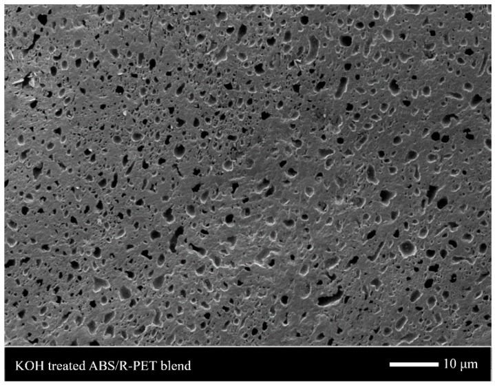
Figure 1 shows the structure of the ABS/R-PET blend treated by a KOH/ethanol solution. Small pores were dispersed in the continuous phase. This means that small PET domains were dispersed in ABS terpolymer since the KOH solution hydrolyzed PET selectively. Hence, similar to other immiscible polymer blends, the ABS/R-PET blend also had the sea-island morphology [21,22]. This heterogeneous structure had different sorption or foaming behavior in each polymer region [22,23].
Figure 1.
The SEM image of ABS/R-PET (acrylonitrile-butadiene-styrene/recycled polyethylene terephthalate) blend treated with KOH/ethanol solution. The small pores that were dispersed in the ABS/R-PET domain were formed by etching the R-PET.
3.2. Measurement of Sorption Kinetics
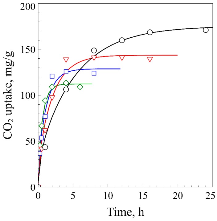
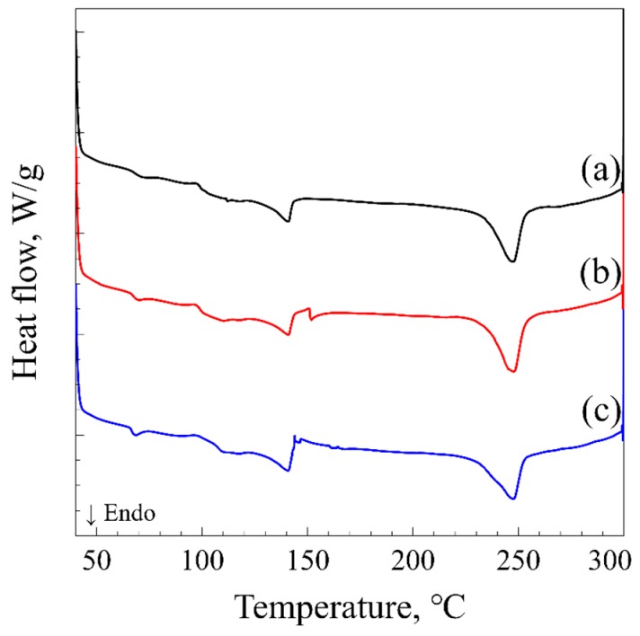
Figure 2 shows the sorption behavior of CO2 in ABS/R-PET disc at 10 MPa. The concentration of CO2 steeply increased initially, and slowly converged to the saturation concentration. The curves were well fitted to Equation (1). The sorption amount and the time that it took to reach the saturation concentration, reached a maximum at −20 °C and decreased as the temperature increased. The CO2 uptake was reduced to approximately 65 % as the temperature increased to 40 °C, while the sorption time decreased to 2 h. The CO2 uptake and diffusivity at −20 °C were 175.3 mg/g and 0.516 × 10⁻⁷ cm2/s (Table 1), which were lower than those of ABS ( and D = 0.228 × 10⁻⁶ cm2/s) [10]. A decrease in CO2 uptake and diffusivity can result from either the CO2-induced crystallization of PET or the poor miscibility between PET and CO2. The sorption curves (Figure 2) and the DSC thermogram (Figure 3) of the polymer blend demonstrate that no CO2-induced crystallization of PET occurred in the ABS/R-PET blend. When the CO2-induced crystallization occurs in a neat PET sample, a “knee-like” curve [11] is observed because the absorbed CO2 in PET is excluded from the polymer matrix after the crystallization. This behavior was not observed in the polymeric blend. In addition, the thermogram of the microcellular foams did not significantly change compared to the unprocessed sample (Figure 3). Thus, no considerable CO2-induced crystallization occurred since the ABS terpolymer prevents the chain movement of R-PET polymer as Zhao et al. observed [12].
Figure 2.
The CO2 sorption kinetics of ABS/R-PET at 10 MPa and the temperature of −20 °C (Circle), 0 °C (Triangle), 20 °C (Square), and 40 °C (Diamond). The experimental data were fitted to Equation (2). The amount of CO2 absorbed in the blend increased as the saturation temperature decreased, whereas the time to reach the saturation became longer.
Table 1.
The saturation concentrations (Csat) and diffusion coefficients (D) of CO2 in ABS/R-PET blend.
| Saturation Temperature, °C | Csat, mg/g a | D, 10−7 cm2/s a |
|---|---|---|
| −20 | 175.3 (14.25) | 0.516 (0.17) |
| 0 | 143.7 (11.80) | 1.304 (0.47) |
| 20 | 128.8 (15.75) | 2.264 (1.03) |
| 40 | 112.4 (5.40) | 4.083 (0.85) |
a indicates the uncertainties of the estimation with 95% confidence bounds were presented in parentheses.
Figure 3.
Differential scanning calorimetry (DSC) thermogram of (a) unprocessed ABS/R-PET blend, (b) ABS/R-PET blend after sorption process, and (c) ABS/R-PET blend foamed at 60 °C. The exothermic peak near 150 °C is the cold crystallization peak of PET, and the endothermic peak at 250 °C is the melting peak of PET.
Thus, low CO2 uptake and diffusivity in the polymeric blend resulted from the weak PET/CO2 interaction. The Hansen solubility parameter (HSP) can be utilized to compare the extent of interaction between polymers and CO2 [24]. The HSPs of polymers were obtained from Hansen’s work [25] and those of CO2 at −20 °C and 10 MPa were calculated based on the Williams method [26]. Since the absorption of CO2 in the ABS matrix was largely dependent on the polybutadiene (PB) portion [9], the preference of CO2 was examined through the comparison of the Hansen distance () of PET and PB. It was hypothesized that the HSPs of polymers do not vary significantly from those at the ambient condition since the volumetric properties of polymeric materials do not largely depend on the pressure. The Hansen distance was determined by the following equation [27]:
| (3) |
where is the energy from the dispersion force of the component, is the energy from the dipolar intermolecular force of the component, and is the energy from the hydrogen bond of the component. The Hansen distance between CO2 and PB was closer than that between CO2 and PET (Table 2). It means that CO2 was favorably absorbed in ABS domains. Thus, the existence of PET in the blend caused a decrease in CO2 uptake and diffusivity in the blend.
Table 2.
The Hansen solubility parameters (HSPs) of CO2 and polymers and the Hansen distance from CO2.
| Component | ||||
|---|---|---|---|---|
| CO2 (−20 °C, 10 MPa) | 14.6 | 5.1 | 6.0 | - |
| PET | 18.7 | 6.3 | 6.7 | 8.3 |
| PB | 17.3 | 2.3 | 3.4 | 6.6 |
3.3. Characterization of the ABS/R-PET Microcellular Foams
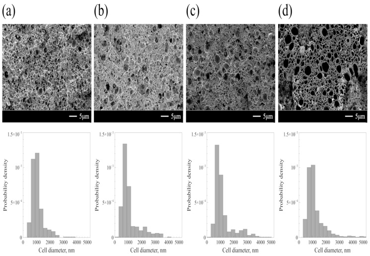
Figure 4 shows the SEM images and the cell size distributions of ABS/R-PET foams. As the foaming temperature () increased, larger cells were more frequently observed and the cell size distributions broadened. This result was consistent with that of ABS polymeric foams, which showed an increase of the mean cell diameter as the temperature changed from 50 to 120 °C [9]. The mean cell diameter slightly increased from to 1195 . This slight increase of the cell diameter can be explained as follows: When was low, the cell growth was limited by the rigidity of the polymer matrix. At high , the growth rate of the CO2 bubble increased and the polymer matrix became less viscous by an active chain movement. Thus, the expansion of CO2 can push the polymeric wall enveloping the bubble, which facilitates the cell growth [28].
Figure 4.
SEM images and the size distribution curves of ABS/R-PET blend foams. Samples were foamed at (a) 60 °C, (b) 80 °C, (c) 100 °C, and (d) 120 °C after sorption with CO2 at −20 °C, 10 MPa over a period of 24 h. The depressurization time was one second. The size distribution curves became broader and long-tailed as the increased.
On the other hand, the standard deviation of cell diameters at was much smaller than those at higher s (Table 3). This reflects the structural heterogeneity of the polymer blend. As mentioned above, the butadiene portion of the ABS terpolymer was more CO2-philic than PET. The of an ABS terpolymer drastically decreased under a high-pressure CO2 environment. Furthermore, the ABS terpolymer was rubbery at any sorption temperatures when the sorption pressure is higher than 5 MPa [8]. In contrast, PET has a low CO2 uptake, and the extent of the depression was relatively low. The of PET under the high-pressure CO2 environment decreased to approximately 40 °C [29]. Hence, the state of each ABS and PET polymer was rubbery and glassy respectively when the blend was saturated with CO2 at −20 °C, 10 MPa. This heterogeneous structure of the polymer blend led to a formation of small cells in the ABS domain at . The foams should be only created in the amorphous ABS region, since the PET region was glassy. Also, the presence of a glassy PET domain resulted in relatively uniform cells with a mean diameter of since they restricted the cell growth. When was 80 °C, PET domain also became rubbery, which resulted in the formation of cells in both domains. Consequently, an increase of the cell diameter and broadening of the size distribution at high came from the increase of the extent of cell growth and the heterogeneous structure of the polymeric blend. The obtained foam structure which has both large and small cells, can improve both the thermal and the mechanical properties [30].
Table 3.
The mean cell diameter and standard deviation of ABS/R-PET blend foams.
| Mean Cell Diameter, nm | Standard Deviation, nm | |
|---|---|---|
| 60 | 1068 | 445 |
| 80 | 1118 | 686 |
| 100 | 1192 | 717 |
| 120 | 1194 | 701 |
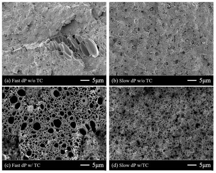
Next, the effect of the depressurization rate was examined. When the thermal contrast method was not applied, both samples after fast and slow depressurization did not show any distinct differences (Figure 5a,b). The cell number densities of the foams with a simple depressurization step (Figure 5a,b) were smaller than those from the additional thermal contrast method (Figure 5c,d). In contrast to the samples without thermal contrast, the foams after the thermal contrast method with fast and slow depressurization rate were different from each other. The mean cell diameter did not change significantly, but the cell number density of the sample from fast depressurization was larger than that from slow depressurization, by a factor of 2.7 (Table 4). This result suggests that the depressurization does not affect cell growth, but cell nucleation. The remaining CO2 concentration after fast depressurization was 175.3 mg/g, which was higher than that after slow depressurization (154.3 mg/g). A sudden pressure drop induced more CO2 to remain in the polymer. Thus, rapid depressurization led to the formation of a large number of cell nuclei, due to the high extent of supersaturation [31]. When the thermal contrast was not applied, these cell nuclei could not grow, since CO2 slowly diffuses out from the polymer matrix. Hence, the effect of the depressurization rate on the bubble nucleation cannot be observed well in Figure 5a,b. On the contrary, dipping the samples into a high-temperature medium allowed the nuclei to grow.
Figure 5.
SEM images of processed ABS/PET blends after (a) depressurization for 1 s, (b) depressurization for 3 min, (c) depressurization for 1 s and thermal contrast at 120 °C, and (d) depressurization for 3 min and thermal contrast at 120 °C. When the thermal contrast was performed after depressurization, a large number of cells appeared.
Table 4.
The properties of the ABS/R-PET blends foamed at 120 °C after fast or slow depressurization.
| Depressurization Rate | Mean Cell Diameter, nm |
Sample Density, g/cm3 |
Cell Number Density, 1012 cells/cm3 |
The Remaining CO2, mg/g a |
|---|---|---|---|---|
| Fast | 1195 | 0.36 | 1.86 | 175.3 |
| Slow | 1060 | 0.40 | 0.69 | 154.3 |
a indicates the remaining CO2 concentration before thermal contrast process.
4. Conclusions
In conclusion, this work demonstrated that a microcellular foam of the ABS/R-PET blend can be successfully prepared using subcritical CO2 as a blowing agent. The microcellular foams had a mean cell size of , and the size distribution largely depended on the foaming temperature. As the foaming temperature increased, larger cells were observed because both ABS and R-PET became rubbery by CO2-induced plasticization. The depressurization rate largely influenced the extent of the cell nucleation. Hence, a fast depressurization rate and the large temperature difference between the saturation temperature and the foaming temperature are desirable in the preparation of ABS/R-PET microcellular foams. Considering that a large amount of the post-consumer PET is used as a constituent of a polymer blend, this work will be helpful for the extended utilization of recycled PET.
Acknowledgments
Authors are grateful to C.-J. Kim, School of Mechanical and Aerospace Engineering at Seoul National University, for good discussions and comments during the research.
Author Contributions
Conceptualization, B.K.P. and Y.-W.L.; data curation, D.E.K.; formal analysis, D.E.K.; funding acquisition, B.K.P.; investigation, D.E.K.; methodology, D.E.K. and B.K.P.; project administration, B.K.P. and Y.-W.L.; supervision, Y.-W.L.; validation, B.K.P.; writing—original draft, D.E.K.; writing—review and editing, Y.-W.L.
Funding
This research was supported by Grant (18CTAP-C129752-02) from Technology Advancement Research Program funded by Ministry of Land, Infrastructure and Transport of the Korean government and Grant (NRF-2018R1A2B2008196) from National Research Foundation of Korea funded by the Ministry of Science and ICT.
Conflicts of Interest
The authors declare no conflict of interest. Authors identify and declare no personal circumstances or interest that may be perceived as inappropriately influencing the representation or interpretation of research results. The funders had no role in the design of the study; in the collection, analyses, or interpretation of data; in the writing of the manuscript, and in the decision to publish the results.
References
- 1.Barnes D.K.A., Galgani F., Thompson R.C., Barlaz M. Accumulation and fragmentation of plastic debris in global environments. Philos. Trans. R. Soc. Lond. B Biol. Sci. 2009;364:1985–1998. doi: 10.1098/rstb.2008.0205. [DOI] [PMC free article] [PubMed] [Google Scholar]
- 2.Park S.H., Kim S.H. Poly (ethylene terephthalate) recycling for high value added textiles. Fash. Text. 2014;1:1. doi: 10.1186/s40691-014-0001-x. [DOI] [Google Scholar]
- 3.Papadopoulou C.P., Kalfoglou N.K. Comparison of compatibilizer effectiveness for PET/PP blends: Their mechanical, thermal and morphology characterization. Polymer. 2000;41:2543–2555. doi: 10.1016/S0032-3861(99)00442-5. [DOI] [Google Scholar]
- 4.Chaudhari K., Kale D. Impact modification of waste PET by polyolefinic elastomer. Polym. Int. 2003;52:291–298. doi: 10.1002/pi.1071. [DOI] [Google Scholar]
- 5.Mbarek S., Jaziri M., Carrot C. Recycling poly(ethylene terephtalate) wastes: Properties of poly(ethylene terephtalate)/polycarbonate blends and the effect of a transesterification catalyst. Polym. Eng. Sci. 2006;46:1378–1386. doi: 10.1002/pen.20625. [DOI] [Google Scholar]
- 6.Cook W.D., Zhang T., Moad G., Van Deipen G., Cser F., Fox B., O’Shea M., Van Deipen G., Cser F., Fox B., et al. Morphology-Property Relationships in ABS/PET Blends. 1. Compositional Effects. J. Appl. Polym. Sci. 1996;62:1699–1708. doi: 10.1002/(SICI)1097-4628(19961205)62:10<1699::AID-APP21>3.0.CO;2-W. [DOI] [Google Scholar]
- 7.Paul S., Kale D.D. Blends of acrylonitrile-butadiene-styrene/waste poly(ethylene terephthalate) compatibilized by styrene maleic anhydride. J. Appl. Polym. Sci. 2001;80:2593–2599. doi: 10.1002/app.1370. [DOI] [Google Scholar]
- 8.Nawaby A.V., Handa Y.P., Liao X., Yoshitaka Y., Tomohiro M. Polymer—CO2 systems exhibiting retrograde behavior and formation of nanofoams. Polym. Int. 2007;56:67–73. doi: 10.1002/pi.2112. [DOI] [Google Scholar]
- 9.Forest C., Chaumont P., Cassagnau P., Swoboda B., Sonntag P. Generation of nanocellular foams from ABS terpolymers. Eur. Polym. J. 2015;65:209–220. doi: 10.1016/j.eurpolymj.2014.11.006. [DOI] [Google Scholar]
- 10.Yoon T.J., Kong W., Kwon D.E., Park B.K., Lee W., II, Lee Y.W. Preparation of solid-state micro- and nanocellular acrylonitrile-butadiene-styrene (ABS) foams using sub- and supercritical CO2 as blowing agents. J. Supercrit. Fluids. 2017;124:30–37. doi: 10.1016/j.supflu.2017.01.004. [DOI] [Google Scholar]
- 11.Li D., Liu T., Zhao L., Yuan W. Controlling sandwich-structure of PET microcellular foams using coupling of CO2 diffusion and induced crystallization. AIChE J. 2012;58:2512–2523. doi: 10.1002/aic.12764. [DOI] [Google Scholar]
- 12.Zhao G., Pan Z., Wang J., Guo Q., Cai X. Toughening and Compatibilization of Acrylonitrile–Butadiene–Styrene/Poly (Ethylene Terephthalate) Blends. J. Macromol. Sci. Part B. 2011;50:821–830. doi: 10.1080/00222348.2010.483386. [DOI] [Google Scholar]
- 13.Kumar V., Weller J.E. A Process to Produce Microcellular PVC. Int. Polym. Process. 1993;8:73–80. doi: 10.3139/217.930073. [DOI] [Google Scholar]
- 14.Matuana L.M. Solid state microcellular foamed poly(lactic acid): Morphology and property characterization. Bioresour. Technol. 2008;99:3643–3650. doi: 10.1016/j.biortech.2007.07.062. [DOI] [PubMed] [Google Scholar]
- 15.Hu D., Gu Y., Liu T., Zhao L. Microcellular foaming of polysulfones in supercritical CO2 and the effect of co-blowing agent. J. Supercrit. Fluids. 2018;140:21–31. doi: 10.1016/j.supflu.2018.05.017. [DOI] [Google Scholar]
- 16.Crank J. The Mathematics of Diffusion. 2nd ed. Oxford University Press; Oxford, UK: 1975. [Google Scholar]
- 17.Schneider C.A., Rasband W.S., Eliceiri K.W. NIH Image to ImageJ: 25 years of image analysis. Nat. Methods. 2012;9:671–675. doi: 10.1038/nmeth.2089. [DOI] [PMC free article] [PubMed] [Google Scholar]
- 18.Legland D., Arganda-Carreras I., Andrey P. MorphoLibJ: Integrated library and plugins for mathematical morphology with ImageJ. Bioinformatics. 2016;32:btw413. doi: 10.1093/bioinformatics/btw413. [DOI] [PubMed] [Google Scholar]
- 19.Forest C., Chaumont P., Cassagnau P., Swoboda B., Sonntag P. Nanofoaming of PMMA using a batch CO2 process: Influence of the PMMA viscoelastic behaviour. Polymer. 2015;77:1–9. doi: 10.1016/j.polymer.2015.09.011. [DOI] [Google Scholar]
- 20.Park B.K., Hwang D.J., Kwon D.E., Yoon T.J., Lee Y.-W. Fabrication and Characterization of Multiscale PLA Structures Using Integrated Rapid Prototyping and Gas Foaming Technologies. Nanomaterials. 2018;8:575. doi: 10.3390/nano8080575. [DOI] [PMC free article] [PubMed] [Google Scholar]
- 21.Otsuka T., Taki K., Ohshima M. Nanocellular Foams of PS/PMMA Polymer Blends. Macromol. Mater. Eng. 2008;293:78–82. doi: 10.1002/mame.200700257. [DOI] [Google Scholar]
- 22.Taki K., Nitta K., Kihara S.-I., Ohshima M. CO2 foaming of poly(ethylene glycol)/polystyrene blends: Relationship of the blend morphology, CO2 mass transfer, and cellular structure. J. Appl. Polym. Sci. 2005;97:1899–1906. doi: 10.1002/app.21930. [DOI] [Google Scholar]
- 23.Di Maio E., Kiran E. Foaming of polymers with supercritical fluids and perspectives on the current knowledge gaps and challenges. J. Supercrit. Fluids. 2018;134:157–166. doi: 10.1016/j.supflu.2017.11.013. [DOI] [Google Scholar]
- 24.Salerno A., Domingo C. Polycaprolactone foams prepared by supercritical CO2 batch foaming of polymer/organic solvent solutions. J. Supercrit. Fluids. 2019;143:146–156. doi: 10.1016/j.supflu.2018.08.006. [DOI] [Google Scholar]
- 25.Hansen C.M. Hansen Solubility Parameters: A User’s Handbook. CRC Press; Boca Raton, FL, USA: 2007. [Google Scholar]
- 26.Williams L.L., Rubin J.B., Edwards H.W. Calculation of Hansen Solubility Parameter Values for a Range of Pressure and Temperature Conditions, Including the Supercritical Fluid Region. Ind. Eng. Chem. Res. 2004;43:4967–4972. doi: 10.1021/ie0497543. [DOI] [Google Scholar]
- 27.Marcus Y. Solubility parameter of carbon dioxide—An enigma. ACS Omega. 2018;3:524–528. doi: 10.1021/acsomega.7b01665. [DOI] [PMC free article] [PubMed] [Google Scholar]
- 28.Tsivintzelis I., Pavlidou E., Panayiotou C. Biodegradable polymer foams prepared with supercritical CO2-ethanol mixtures as blowing agents. J. Supercrit. Fluids. 2007;42:265–272. doi: 10.1016/j.supflu.2007.02.009. [DOI] [Google Scholar]
- 29.Zhong Z., Zheng S., Mi Y. High-pressure DSC study of thermal transitions of a poly(ethylene terephthalate)/carbon dioxide system. Polymer. 1999;40:3829–3834. doi: 10.1016/S0032-3861(98)00594-1. [DOI] [Google Scholar]
- 30.Ma Z., Zhang G., Yang Q., Shi X., Shi A. Fabrication of microcellular polycarbonate foams with unimodal or bimodal cell-size distributions using supercritical carbon dioxide as a blowing agent. J. Cell. Plast. 2014;50:55–79. doi: 10.1177/0021955X13503849. [DOI] [Google Scholar]
- 31.Xu Z.-M., Jiang X.-L., Liu T., Hu G.-H., Zhao L., Zhu Z.-N., Yuan W.-K. Foaming of polypropylene with supercritical carbon dioxide. J. Supercrit. Fluids. 2007;41:299–310. doi: 10.1016/j.supflu.2006.09.007. [DOI] [Google Scholar]


