Abstract
Water-based drilling mud (WBM) is a non-Newtonian fluid that has a variety of applications such as in transporting cuttings during drilling, protecting the borehole, and cooling the drill bit. With the development of nano-technology, various nanoparticles have been synthesized and have been added to WBM to improve its performance. Shear thinning is the most important factor in drilling mud and this attribute can be improved when two-dimensional particles are added. MoS2 nanoparticles, which represent a typical two-dimensional material, are easy to synthesize in large quantities and have a high thermal conductivity and low coefficient of friction. Since the two-dimensional structure, thermal conductivity, and low coefficient of friction of MoS2 would improve the performance of WBM, we experimented with MoS2 nanosheets as an additive, under optimal conditions, using various samples each with uniform sizes and thicknesses of nanosheets. A large amount of MoS2 nanosheets was synthesized, sorted by thickness and diameter, and added to drilling mud. The diameter of MoS2 was divided into a small diameter group (about 100–400 nm) and a big diameter group (about 300–650 nm), and the thickness was divided into 1–2 nm and 5–10 nm groups. Experimental results showed that when MoS2 is added to WBM, shear thinning occurs more strongly. In addition, the addition of MoS2 with a thickness of 1–2 nm and a diameter of 300–650 nm resulted in the highest increase in viscosity and thermal conductivity of WBM. As a result, we experimentally confirmed that MoS2 can be used as an additive to increase the thermal conductivity and viscosity of WBM and to make shear thinning phenomenon more.
Keywords: water-based drilling mud, 2D material, thermal conductivity, shear thinning
1. Introduction
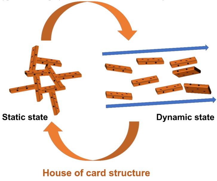
The drilling fluid commonly referred to as drilling mud is used in drilling operations to remove cuttings, control the pressure of the borehole, lubricate and cool the bit and the drill string, form mud cake, and prevent fluid loss [1]. There are various types of drilling muds, such as water-based mud (WBM), oil-based mud (OBM), synthetic-based mud (SBM), and low-density drilling fluid. OBM and SBM exhibit good performance, however, they are more costly than WBM and can cause environmental problems, while low-density drilling fluid is used only in special cases [2]. WBM is the most common mud and is used in many drilling applications. WBM usually consists of bentonite, barite, and polymer added to fresh or saline water. Bentonite shows a bipolar property where the edges of each layer are positive and the surface is negative. For this reason, when bentonite is present in water, each edge part and surface part are partially connected to each other by electrical properties to make a specific structure. This structure is called the house of cards structure [3]. The fluid containing bentonite has a viscosity increase due to this structure under static conditions, and when the flow rate of the fluid is fast, the structure is disturbed and the viscosity drops sharply. This process which the viscosity is high when the flow rate is low and the viscosity is low when the flow rate is high occurs as a reversible process. One of the reasons for the shear thinning phenomenon is that of the house of cards structure. (Figure 1) Barite increases the density of WBM, while typical viscous polymer additives, such as xanthan gum, increase its viscosity [4,5,6].
Figure 1.
Image about when bentonite is in a static state and a dynamic state.
WBM needs to possess various properties, depending on the drilling application in question. Typically, WBM performance needs to be checked during the drilling operation. In case of density, it is necessary that the WBM facilitates maintenance of borehole pressure, while in order to transfer cuttings after penetration, it needs to retain a suitable viscosity. If the viscosity is low, the pressure loss is small, and it is easy to circulate the WBM, however cuttings transport remains an issue, due to low viscosity. High WBM viscosity affects the flow rate, and the all-important shear thinning behavior requires appropriate viscosity. Shear thinning behavior is the most important property of drilling fluid, because when the flow velocity of WBM is low, the viscosity is high and the cuttings are transferred smoothly, and, in contrast, when the flow velocity is high, viscosity is low, which increases the flow rate of WBM, and drilling proceeds well [3,4,5]. In addition, WBM must be an effective lubricant to reduce damage to drill bits, while high thermal conductivity is required, to prevent drill bit overheating [7,8]. In addition, WBM needs to facilitate production of a filter cake layer, to prevent fluid loss [9].
Developments in nanotechnology have led to reports that adding various nanoparticles improved WBM performance. Hydrophilic nanoparticles, such as Fe2O3 or SiO2, have a high surface area per unit mass, resulting in increased viscosity and shear stress of the fluid. Reports have shown that the smaller the nanoparticle, the greater the increased viscosity and shear stress [10,11], while in other cases, nanoparticles were added to WBM to increase shear thinning behavior. Especially shear thinning behaviors of drilling mud when TiO2 is added are shown linearly with increasing TiO2 addition [12,13,14,15,16]. In drilling operations, fluid loss caused by penetration of drilling mud into the reservoir gap has been reduced by adding nanoparticles; in one case, the necessary thickness of the filter cake was reduced by adding two-dimensional, Graphene oxide (GO) particles, which led to reduced fluid loss through raised filter cake impermeability. GO has excellent mechanical strength and good dispersion in water and is also stable. In addition, drilling mud has often alkalinity and GO can be well dispersed in alkalinity so it is used as a drilling mud additive [9,17,18,19]. The properties of WBM can be improved by selecting for specific nanoparticle properties, and it has been demonstrated, for example, that the thermal conductivity of WBM was improved by adding nanoparticles with high thermal conductivity [8,16]. In the case of Copper oxide (CuO) not only increases the thermal conductivity of drilling mud but also has stability in high temperature and high-pressure condition (HPHT) [16]. In addition, nano-clay such as palygorskite (Pal) showed a noticeable increase in viscosity of drilling mud even when added in small amounts, and was stable also in HPHT condition [13].
Transition metal chalcogenides (TMD) are substances in which groups 4 to 10 transition metals, and group 16 gases, are bonded. MoS2 is a representative TMD material, with a two-dimensional structure, and a van der Waals bond between layers; it also exhibits an extremely low coefficient of friction, and it is used as an additive in lubricating solutions [20]. Previous research showed that MoS2, when added to OBM and WBM, improved the lubricant performance of the drilling mud [21,22].
The electrical and thermal properties of MoS2 depend on the phase, size, and thickness of its structure. The theoretical thermal conductivities of 1T phase, single layer, and 2H phase, single layers of MoS2, are 32 ± 3 W/m·K, and 40 ± 4 W/m·K, respectively [23]. There has also been a theoretical result in relation to differences in the thermal conductivity of 2H phase MoS2, depending on whether it was present as a single layer or the bilayer, of 34.5 W/m·K, and 54 W/m·K, respectively. Although the theoretical thermal conductivity of MoS2 has differed between reports, results have consistently shown that the thicker the layer and the larger the particle diameter, the higher the thermal conductivity. It has been experimentally demonstrated that thermal conductivity is 85–110 W/m·K, for bulk, 2H MoS2 [24,25,26,27,28,29,30]. The thickness of MoS2 also affects the coefficient of friction, with thicker MoS2 layers reportedly giving lower coefficients of friction [31].
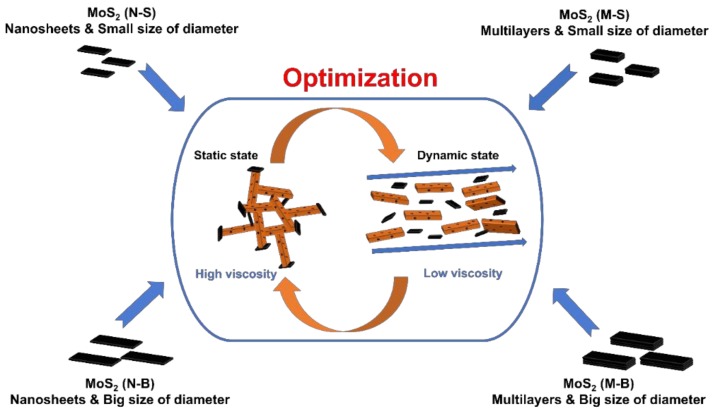
In previous studies, MoS2 was added to WBM to make a lubricant, but the addition of a small amount (<1 wt %) did not affect viscosity or shear stress. We added bulk MoS2 to increase WBM thermal conductivity. The interaction between bentonite and MoS2 makes high viscosity of the WBM when the WBM is in a static state, and low friction coefficient of MoS2 cause viscosity of WBM to drop sharply in a dynamic state (Figure 2). We synthesized MoS2 nanoparticles, using two representative methods: ultrasonication and Li-intercalation [32,33,34]. The MoS2 nanosheets synthesized by the Li-intercalation method were divided into small and large diameter sheets (‘Nanosheets-Small’ and ‘Nanosheets-Big’: N-S and N-B, respectively). For MoS2 multilayered sheets obtained through sonication, we divided the products into small and large diameter, multilayer sheets (‘Multilayers-Small’, and ‘Multilayers-Big’: M-S and M-B respectively). The four synthesized sheet samples (N-S, N-B, M-S, and M-B) were added to the base fluid, as shown in Figure 2.
Figure 2.
WBM synthesized by adding MoS2 with different size and thickness to the base fluid.
If the same concentration of the different MoS2 samples was added, the surface area per unit mass of MoS2 would be different, due to the difference in size, as the addition of MoS2 nanosheets will give rise to a larger surface area than the addition of MoS2 multilayers. However, the thicker the MoS2, the higher the thermal conductivity and the lower the coefficient of friction, and we tried to resolve performance variations brought about by differences between surface areas through experimentation.
The base fluids, consisting of water, bentonite, and various amounts of MoS2 nanoparticles, are shown in Table S1, together with their measured rheological properties and thermal conductivity. We experimented which thickness and diameter of the MoS2 additions, in terms of their ability to enhance the thermal conductivity and rheological properties for WBM, and generally investigated whether MoS2 could be a multifunctional nano-additive, capable of bringing other improvements to WBM.
2. Experimental Procedures
2.1. Preparation of Base Fluid and MoS2 Nanoparticles
The base fluid consisted of 5 wt % bentonite and deionized water (DI water). Bentonite was supplied by Clariant Korea (Seoul, Korea). FE-SEM image of bentonite is attached to Supplementary Materials (Figure S1). The reason for using only bentonite and DI water as base fluid is to confirm the rheological properties of MoS2. MoS2 was prepared in four different sizes (N-S, N-B, M-S, and M-B) and added to the base fluid at different concentrations (1 wt %, 3 wt %, and 5 wt %). The MoS2 Nanosheet was fabricated by the Li-intercalation method and then the diameter was controlled by adjusting the centrifugal speed and the sonication power. MoS2 Multilayers adjusted the size of the particles by applying only sonication power to the MoS2 raw material. Information on the components in WBM, with MoS2 nanoparticles, can be found in Table S1.
2.2. Synthesizing MoS2 Nanosheets and Size Control
MoS2, Hexane, and Butyl lithium were purchased from Sigma-Aldrich. In this work, we used the Li-intercalation method to prepare the MoS2 nanosheet published previously [34]. Ten gram MoS2 (<2 µm) was added to 33 mL of n-Hexane and 17 mL of n-Butyllithium solution (2.5 M in hexanes), and stored in a container filled with nitrogen gas, for 120 h. It was then centrifuged at 8000 RPM for 2 min, after which the precipitate was retained and the suspension was discarded. This process was repeated twice, and the precipitate was dried on a hotplate until the hexane evaporated. DI water was then added, the solution was sonicated for 1 h in a sonic bath, and centrifuged for 5 min at 8000 RPM, after which the precipitate was retained and the suspension was discarded. This was again repeated twice, adding DI water, centrifuging, and discarding the liquid. Subsequently, the MoS2 precipitated by centrifugation, at 500 RPM for 5 min, was referred to as a large-sized MoS2 nanosheet (N-B). For the next group, after centrifugation at 8000 RPM for 5 min, the precipitate was sonicated at 60 W for 1 h by ultrasonicator (SONICS VCX0750, Sonics & Materials, Newtown, CT, USA), and was then classified as small-sized MoS2 nanosheets (N-S). After creation, the MoS2 nanoparticles were re-dispersed in a sonic bath, before adding to the base fluid.
2.3. Synthesizing MoS2 Multilayers and Size Control
The sonication method is a method of exfoliation MoS2 using ultrasonic waves. The probe-ultrasonicator was used for that method. Each aliquot of the required MoS2 was placed in a 70 mL vial, with DI water, and was then sonicated, for 1 h at 60 W, or 30 min at 10 W. Each was classified as either multilayered, small-sized MoS2 (M-S), or multilayered, big-sized MoS2 (M-B). The MoS2 nanoparticles were then added directly to the base fluid.
2.4. Characterization
Field-emission scanning electron microscopy (FE-SEM, SIGMA/ Carl Zeiss 300 VP, Carl Zeiss, Oberkochen, Germany) was used to measure the structures and sizes of the created MoS2 nanoparticles, and UV-vis absorption spectra (V-670 UV-Vis spectrophotometer, JASCO, Mary’s Court Eaaston, MD, USA) were measured to analyze their optical properties. Size distributions of the MoS2 nanoparticles were measured by Dynamic Light Scattering (Otsuka ELSZ-1000, Otsuka electronics, Osaka, Japan), and their thicknesses were determined using contact-mode atomic force microscopy (AFM, XE-100, Park systems, Suwon, Korea). For the fluid containing nanoparticles, the transition hot wire method was used to measure thermal conductivity, with a KD2 pro (Decagon, Pullman, WA, USA) used for the actual thermal conductivity measurements. Transition hot wire method is the most common way to measure nanofluid’s thermal conductivity. When the probe gets electric power, the temperature of the wire rises. The method of calculating the thermal conductivity using the temperature gradient characteristic of this wire is called the transition hot wire method [35,36,37,38]. The thermal conductivity is calculated as follows.
| (1) |
λ = Thermal conductivity of the sample (W/m·K), q = Generated heat per unit length of sample/time (W/m), t1,t2 = measure time length (sec), T1, T2 = Temperature at t1, t2 (K).
Thermal conductivity was measured three times, and the average value was rounded off to the fourth digit. Rheological property is a term which generally refers to changes in viscosity and yield stress, with shear rate. In this study, a rheometer (Anton Paar MCR 301, Anton Paar Graz, Austria) was used to measure the rheological properties of drilling mud, and PP 50 (parallel plate with diameter 50 mm) was used for the measurement value. A parallel plate accessory (PP 50) was characterized by the flat parts touching the fluid, and it can be confirmed that the samples were stable when measured. By using PP 50, the rheological properties of the various drilling mud compounds tested were measured by using strain control. Shear rate control is an experimental method to measure shear stress with varying shear rate. In this study, shear stress was measured in a shear rate range of between 0.008/s to 1000/s. The viscosity was then calculated by dividing the measured stress by the applied shear rate.
3. Results and Discussion
3.1. Synthesis and Characterization of MoS2
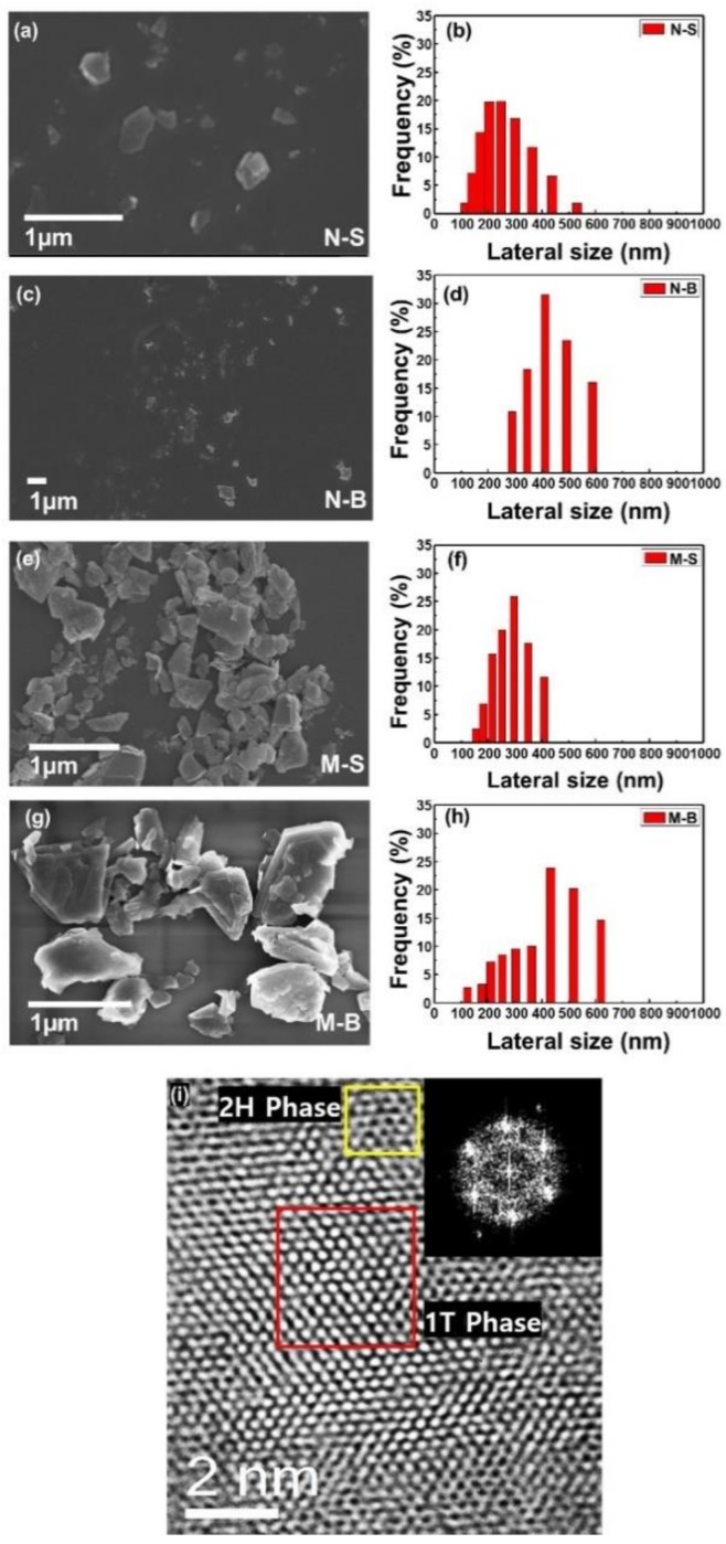
Figure 3 shows FE-SEM images and DLS graphs of the fabricated MoS2 nanoparticles. The particle size of the MoS2 nanosheets was divided by sonication power and centrifuge speed. When the MoS2 nanosheets were precipitated at 500 rpm, the average size distribution of N-B was found to be between 300 and 600 nm, with up to 1 µm size confirmed, by FE-SEM. After the MoS2 was exfoliated, no strong sonication was performed, so that the MoS2 flakes were large, and only the heavier nanoparticles submerged enough to precipitate at low centrifuge speed. In contrast, when N-S was precipitated, at the relatively high speed of 8000 rpm, and ultrasonicated, particles diameters over 100 nm were found, with the majority within the range of 100–400 nm. The diameter distributions of the MoS2 multilayers were also distinguished by the different ultrasonication power and times applied: M-S had 100–400 nm particles, while M-B had a size range of 400–650 nm, while using FE-SEM revealed particles greater than 1 µm. Creating the different sized MoS2 was found to be relatively simple, by varying the ultrasonication power. TEM was also measured and the data showed 1T and 2H phases on MoS2 surface. The hexagonal structure of MoS2 was confirmed by an electron diffraction image.
Figure 3.
FE-SEM images and DLS graphs of MoS2 N-S (a,b), N-B (c,d), M-S (e,f), and M-B (g,h). The scale bar indicates 1 µm in all images of FE-SEM. In order to compare the diameter distribution of MoS2, the lateral size and frequency scale were made equal. TEM and electron diffraction images indicate the phase of MoS2 (i).
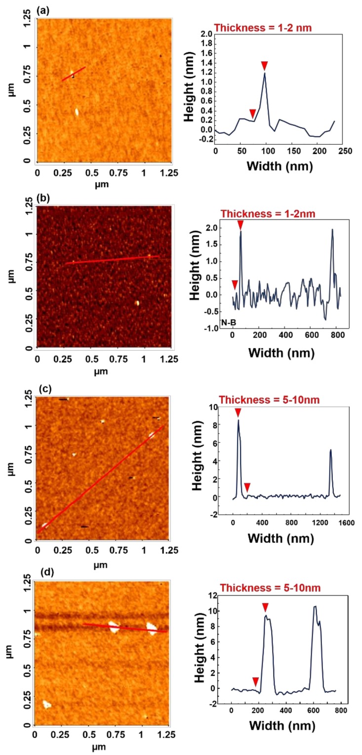
Figure 4 indicates the thicknesses of nanosheets and multilayers, measured by AFM. The MoS2 nanoparticles dispersed in DI water were deposited on a silicon substrate, without spin-coating, for AFM measurement. N-S was shown to have a thickness of 1 nm, which roughly corresponds to a single layer [39]. The value of N-B was measured to be 2 nm, which indicated that N-B was bilayered and that the nanosheets were 1–2 layers thick. On the other hand, the thicknesses of M-S and M-B were between 5–10 nm, which would require more than 5 layers, at least, and these results indicated that nanosheets and multilayers could be clearly differentiated, based on relative thickness.
Figure 4.
AFM images of (a) N-S, (b) N-B, (c) M-S, and (d) M-B. The width and height indicate the value of the red line in the left image.
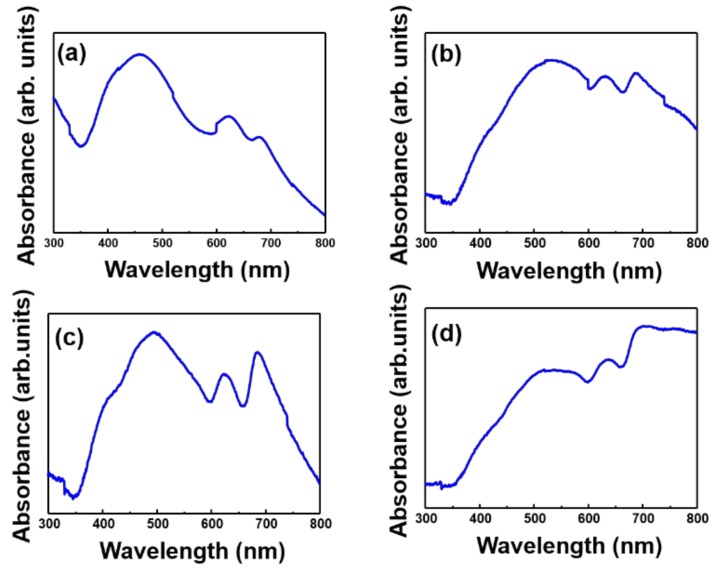
Figure 5 shows the UV-vis spectra of MoS2 of different sizes and thicknesses. N-S, which was mostly composed of a single layer, showed a peak at 622 nm and 678 nm. For N-B, the peak point shifted to 630.5 nm and 686.5 nm, due to the mixture of single and bilayers. When compared to the difference in the thickness of N-S and N-B in the AFM data, the imagery in Figure 5 is convincing. In previous research, for a single layer of the 2H phase, peaks appeared at 617 nm and 670 nm [40]. Since M-S is much thicker than a single layer, there is a big difference in peak point, while the peak point of M-B was seen to be similar to that for MoS2 raw material. Overall, the UV data showed results which were consistent with the results from the FE-SEM, DLS, and AFM analyses, as shown above.
Figure 5.
UV-vis spectra of (a) N-S, (b) N-B, (c) M-S, and (d) M-B. The difference in peak points for each graph is related to the change in the thickness of MoS2.
3.2. Rheological Properties of WBM
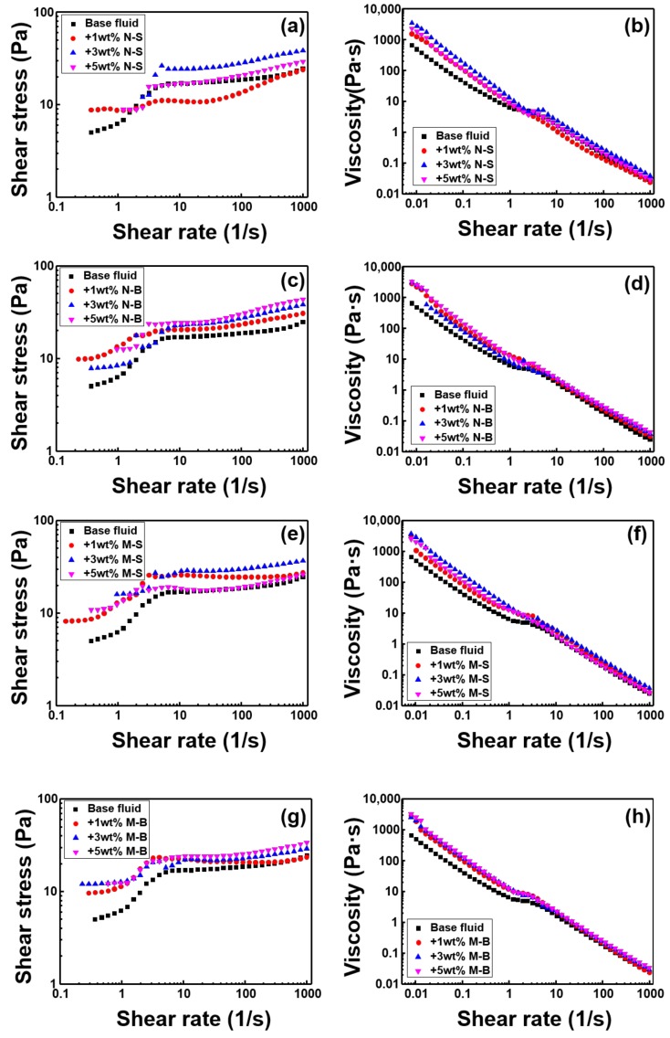
Figure 6 shows the rheological properties. When the shear rate was very small, it showed positive shear stress, rather than 0, which indicated that all kinds of drilling mud have yield stress. MoS2 type N-S (Figure 3a) did not show a linear increase as the concentration increased to 1, 3, 5 wt %. Even the N-S 1 wt % graph shows that after passing through the intermediate peak point (shear rate = 1–10), the viscosity and shear stress were lower than those of the base fluid. The shear stress data shows that the slope of the increased shear stress, according to the shear rate, was less than 1. In the case of Newtonian fluids, considering the slope of 1, the drilling mud with N-S added was very strong, in terms of shear thinning material. Drilling mud with N-B added is also considered strong shear thinning material, as its shear rate was less than 1. In addition, the viscosity and shear stress of the drilling mud with N-B increased, in comparison with the base fluid, and there was a linear relationship between the concentration of N-B and the increase in shear stress, after a certain shear rate interval (1–10). When M-S was added, all of the rheological properties increased in comparison with the base fluid, although as the concentration increased, neither the shear stress, nor viscosity, nor even the yield stress, increased linearly. In order to obtain the correlation between the MoS2 addition concentration and increased shear stress, the N-S and M-S graphs were studied, and it could be confirmed that the diameter of MoS2 needed to be larger than a certain size. M-B also appeared to exhibit shear thinning, similarly to the other three MoS2 samples. In general, drilling mud shear stress and viscosity were enhanced linearly, with increasing concentration, although not at all points of the shear rate. When all MoS2 samples were added to the base fluid, viscosity and shear stress were increased at a lower shear rate than that of base fluid. It was also confirmed that MoS2 is a particle that strongly strengthened shear thinning.
Figure 6.
The shear stress and viscosity of WBM are classified according to the MoS2 particle size and compared with the particle concentration. (a) and (b) N-S, (c) and (d) N-B, (e) and (f) M-S, and (g) and (h) M-B.
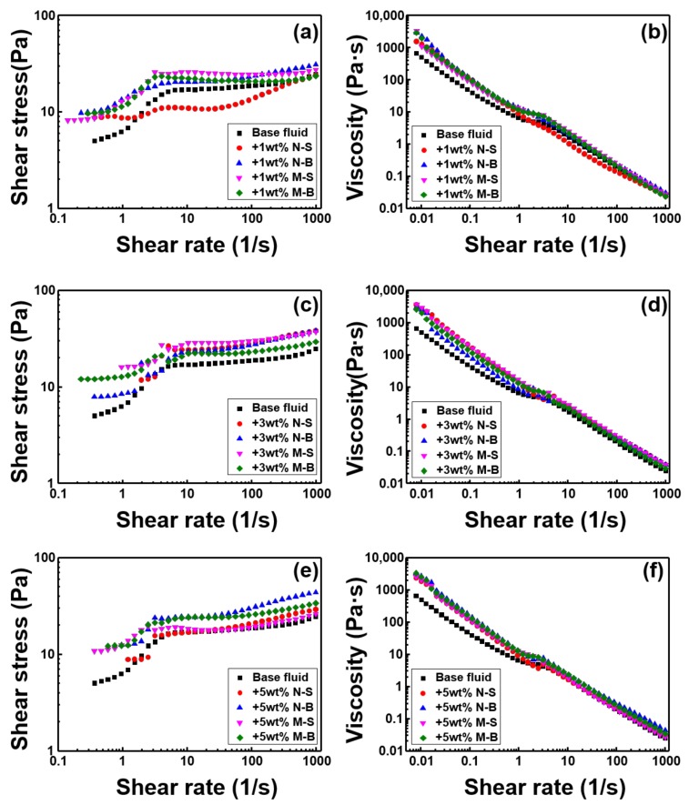
Figure 7 shows the rheological properties of MoS2 according to size and thickness at the same concentration. From the viewpoint of the viscous additive, the viscosity and shear stress were clearly increased when 1 wt % of MoS2 was added, in contrast to the base fluid, except for the N-S sample. However, Figure 7b shows N-S to be the most definitive shear thinning sample. When 3 wt % of MoS2 was added, M-S was the best performing sample, in terms of viscosity and shear stress, with all samples exhibiting shear thinning properties, even though there was a difference in degree. When 5 wt % MoS2 was added, N-B showed the most increase in viscosity and shear stress, in comparison with the base fluid. In the case of M-S and M-B, shear thinning could be confirmed, even though the surface area per unit mass of MoS2 is less than that of N-S or N-B, due to their thickness. It can be seen that the shear thinning property of MoS2 can be attributed to not only its two-dimensional structure but also to its low coefficient of friction.
Figure 7.
The shear stress and viscosity of WBM are compared according to the particle size at the same concentration of MoS2. (a) and (b) 1 wt %, (c) and (d) 3 wt %, (e) and (f) 5 wt %.
3.3. Thermal Conductivity of WBM
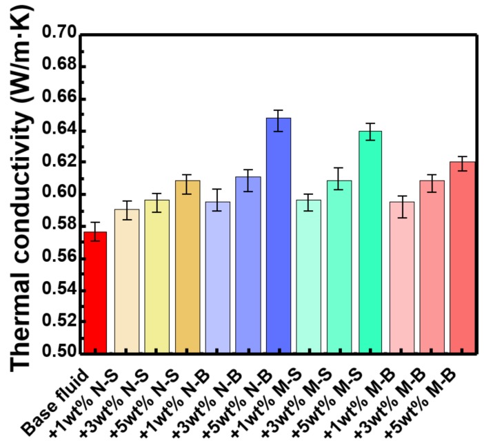
Figure 8 shows the thermal conductivities of the base fluid, and of drilling fluid with MoS2 added. All drilling muds were enhanced linearly with increasing MoS2 concentration because the MoS2 thermal conductivity is much higher than that of the base fluid. The level of enhancement varied depending on the size and thickness of the MoS2 added, as MoS2 nanosheets have been shown to have lower thermal conductivity than MoS2 multilayers, plus, thermal conductivity varies with MoS2 particle diameter. It has been confirmed experimentally that the N-S sample has less increase in thermal conductivity with increasing concentration than other three samples. (N-B, M-S, M-B), when the three factors above were combined. It is noteworthy that even though N-B is a nanosheet, it showed the highest thermal conductivity increase rate, and it has been shown experimentally that the diameter of the MoS2 sample was also an important factor in determining thermal conductivity. The reason why the thermal conductivity of the M-S form was higher than that of the M-B form seems to be that surface area is important. In the case of a single layer, there was no difference in the surface area of MoS2, because it is a two-dimensional structure, however, since the multilayer structure has a three-dimensional structure, the M-B sample surface area must be smaller than that of M-S, while M-S exhibited higher values compared with M-B, for the same reason. Overall, N-B showed the highest degree of thermal conductivity increase, because while MoS2 nanosheets showed low thermal conductivity generally, the larger diameter and wider surface area of the 2D product, in comparison with the multilayer samples, gave rise to this result. The MoS2 M-S sample showed the second highest value, which was attributed to its comparative surface area and thickness. For the N-S sample, thickness and diameter are all of the low thermal conductivity forms, so that, even though it had a wide surface area, its increased thermal conductivity was comparatively low.
Figure 8.
The thermal conductivity for each WBM. Each sample was measured three times and the average value was shown. As the concentration of MoS2 nanoparticle increases, the thermal conductivity increases linearly. Detailed data and the rate of increase can be found in Table S2.
3.4. Optimization of MoS2 for WBM Additive
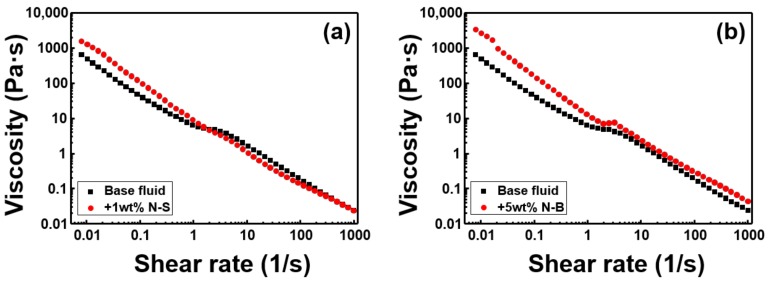
Figure 9 is a rheological graph showing shear thinning and the highest thermal conductivity. In Figure 9a, the viscosity is higher than the base fluid, when the flow velocity is slower, and the viscosity becomes less as the flow velocity increases, in comparison to the base fluid. Figure 9a shows that even when the increase in thermal conductivity was minimal, the effect of shear thinning was quite clear. MoS2 serves as a viscous additive, but the relative drilling mud viscosity increase is often not proportional to the amount of MoS2 added. The most obvious increase in viscosity was when 5 wt % N-B was added to the mud, which also gave the best result for increased thermal conductivity, showing that it was suitable as a multifunctional mud additive, capable of simultaneously increasing drilling mud thermal conductivity and viscosity.
Figure 9.
Shows the viscosity according to the shear rate of WBM. (a) WBM with 1 wt % N-S added to the base fluid showing the most obvious example of shear thinning, (b) WBM with 5 wt % N-B added, which is the case with the highest increase in viscosity and thermal conductivity.
4. Conclusions
We synthesized bulk MoS2 nanoparticles by Li-intercalation and sonication. Nanosheets 1–2 nm thick were fabricated by the Li-intercalation method and were classified into two groups, small, with diameters between 100–400 nm, and large, with diameters between 300–600 nm, by applying different sonication power and centrifuge speed. Multilayers 5–10 nm thick were fabricated, by MoS2 raw material ultrasonication, in DI water. The multilayered forms were also divided into two groups, having small (100–400 nm), and large (400–650 nm) diameters, by adjusting sonication power and time. The four fabricated samples were then added to base fluid at 1, 3, and 5 wt %, depending on the concentration, and their resultant rheological and thermal conductivity properties were measured. MoS2 is a substance that generally increases shear stress and viscosity, but when the MoS2 diameter was small, the extent of increase was not linearly proportional to the concentration. Results also indicated that shear thinning properties, one of the important aspects of drilling mud, were related to the structure and low coefficient of friction of MoS2. MoS2 exhibited different thermal conductivity according to the thickness and diameter of the form in question, and overall, these properties were shown to be the most important factors of the MoS2 sample under consideration. As a result, we confirmed the optimal size and thickness of MoS2 nanosheets used as an additive in drilling mud and confirmed experimentally the effect of the nanosheets in shear thinning, viscosity increase, and increased thermal conductivity.
Supplementary Materials
The following are available online at http://www.mdpi.com/2073-4360/11/2/321/s1, Figure S1: SEM images of bentonite, Table S1: WBM compositions, Table S2: WBM’s thermal conductivity.
Author Contributions
S.H.H. and H.J.J. contributed equally to this work. S.H.H. and H.J.J. carried out the synthesized materials and most of the characterization. M.-J.C. and H.W.J. analyzed materials and characterization. Y.J.K., W.R.H., and S.Y.K. supervised the experiment and prepared the manuscripts. S.Y.K. conceived the idea and designed the experiments. All authors were involved in writing the manuscript.
Funding
This work is supported by a Korea Agency for Infrastructure Technology Advancement grant funded by the Ministry of Land, Infrastructure and Transport (17IFIP-B133622-01) and the Basic Research Laboratory of the NRF funded by the Korean government (2018R1A4A1022647).
Conflicts of Interest
The authors declare no conflict of interest.
References
- 1.Bloys B., Davis N., Smolen B., Bailey L., Houwen O., Reid P., Hodder M. Designing and managing drilling fluid. Oilfield Rev. 1994;6:33–43. [Google Scholar]
- 2.Amani M., Al-Jubouri M., Shadravan A. Comparative study of using oil-based mud versus water-based mud in HPHT fields. Adv. Pet. Explor. Dev. 2012;4:18–27. [Google Scholar]
- 3.Goh R., Leong Y.K., Lehane B. Bentonite slurries—Zeta potential, yield stress, adsorbed additive and time-dependent behaviour. Rheol. Acta. 2011;50:29–38. doi: 10.1007/s00397-010-0498-x. [DOI] [Google Scholar]
- 4.Darley H.C., Gray G.R. Composition and Properties of Drilling and Completion Fluids. Gulf Professional Publishing; Houston, TX, USA: 1988. [Google Scholar]
- 5.Caenn R., Chillingar G.V. Drilling fluids: State of the art. J. Pet. Sci. Eng. 1996;14:221–230. doi: 10.1016/0920-4105(95)00051-8. [DOI] [Google Scholar]
- 6.Vryzas Z., Kelessidis V.C. Nano-based drilling fluids: A review. Energies. 2017;10:540. doi: 10.3390/en10040540. [DOI] [Google Scholar]
- 7.Growcock F.B., Frederick T.P., Reece A.R., Green G.W., Ruffin M.D. Novel lubricants for water-based drilling fluids; Proceedings of the SPE International Symposium on Oilfield Chemistry; Houston, TX, USA. 16–19 February 1999. [Google Scholar]
- 8.Sedaghatzadeh M., Khodadadi A. An improvement in thermal and rheological properties of water-based drilling fluids using multiwall carbon nanotube (MWCNT) Iran J. Oil Gas Sci. Technol. 2012;1:55–65. [Google Scholar]
- 9.Kosynkin D.V., Ceriotti G., Wilson K.C., Lomeda J.R., Scorsone J.T., Patel A.D., Tour J.M. Graphene oxide as a high-performance fluid-loss-control additive in water-based drilling fluids. ACS Appl. Mater. Interfaces. 2011;4:222–227. doi: 10.1021/am2012799. [DOI] [PubMed] [Google Scholar]
- 10.Jung Y., Barry M., Lee J.K., Tran P., Soong Y., Martello D., Chyu M. Effect of nanoparticle-additives on the rheological properties of clay-based fluids at high temperature and high pressure; Proceedings of the AADE National Technical Conference and Exhibition; Houston, TX, USA. 12–14 April 2011; pp. 1–4. [Google Scholar]
- 11.Ghanbari S., Kazemzadeh E., Soleymani M., Naderifar A. A facile method for synthesis and dispersion of silica nanoparticles in water-based drilling fluid. Colloid Polym. Sci. 2016;294:381–388. doi: 10.1007/s00396-015-3794-2. [DOI] [Google Scholar]
- 12.Abdo J., Haneef M.D. Nano-enhanced drilling fluids: Pioneering approach to overcome uncompromising drilling problems. J. Energy Resour. Technol. 2012;134:014501. doi: 10.1115/1.4005244. [DOI] [Google Scholar]
- 13.Abdo J., Haneef M.D. Clay nanoparticles modified drilling fluids for drilling of deep hydrocarbon wells. Appl. Clay Sci. 2013;86:76–82. doi: 10.1016/j.clay.2013.10.017. [DOI] [Google Scholar]
- 14.Sadeghalvaad M., Sabbaghi S. The effect of the TiO2/polyacrylamide nanocomposite on water-based drilling fluid properties. Powder Technol. 2015;272:113–119. doi: 10.1016/j.powtec.2014.11.032. [DOI] [Google Scholar]
- 15.Belayneh M., Aadnøy B.S. Effect of nano-silicon dioxide (SiO2) on polymer/salt treated bentonite drilling fluid systems; Proceedings of the ASME 2016 35th International Conference on Ocean, Offshore and Arctic Engineering; Busan, Korea. 19–24 June 2016. [Google Scholar]
- 16.William J.K.M., Ponmani S., Samuel R., Nagarajan R., Sangwai J.S. Effect of CuO and ZnO nanofluids in xanthan gum on thermal, electrical and high pressure rheology of water-based drilling fluids. J. Petrol. Sci. Eng. 2014;117:15–27. doi: 10.1016/j.petrol.2014.03.005. [DOI] [Google Scholar]
- 17.Lu Z., Hanif A., Ning C., Shao H., Yin R., Li Z. Steric stabilization of graphene oxide in alkaline cementitious solutions: Mechanical enhancement of cement composite. Mater. Des. 2017;127C:154–161. doi: 10.1016/j.matdes.2017.04.083. [DOI] [Google Scholar]
- 18.Lu Z., Hou D., Hanif A., Hao W., Li Z., Sun G. Comparative evaluation on the dispersion and stability of graphene oxide in water and cement pore solution by incorporating silica fume. Cem. Concr. Compos. 2018;94:33–42. doi: 10.1016/j.cemconcomp.2018.08.011. [DOI] [Google Scholar]
- 19.Dikin D.A., Stankovich S., Zimney E.J., Piner R.D., Dommett G.H.B., Evmenenko G., Nguyen S.T., Ruoff R.S. Preparation and characterization of graphene oxide paper. Nature. 2007;448:457. doi: 10.1038/nature06016. [DOI] [PubMed] [Google Scholar]
- 20.Kumari S., Mungse H.P., Gusain R., Kumar N., Sugimura H., Khatri O.P. Octadecanethiol-grafted molybdenum disulfide nanosheets as oil-dispersible additive for reduction of friction and wear. FlatChem. 2017;3:16–25. doi: 10.1016/j.flatc.2017.06.004. [DOI] [Google Scholar]
- 21.Lu F., Du H., Chen Z., Zhang X., Gong H., Xue Y. Stable dispersed MoS2 nanosheets in liquid lubricant with enhanced rate of penetration for directional well. J. Nanomater. 2016 doi: 10.1155/2016/8563870. [DOI] [Google Scholar]
- 22.Agonafir M.B., Wrobel S. The Effect of MoS2-and graphene nanoparticles on the properties & performance of polymer/salt treated bentonite. IJNN. 2017;8:59–71. [Google Scholar]
- 23.Mortazavi B., Rabczuk T. Multiscale modelling of heat conduction in all-MoS2 single-layer heterostructures. RSC Adv. 2017;7:11135–11141. doi: 10.1039/C6RA26958C. [DOI] [Google Scholar]
- 24.Zhang X., Sun D., Li Y., Lee G.H., Cui X., Chenet D., Hone J.C. Measurement of lateral and interfacial thermal conductivity of single-and bilayer MoS2 and MoSe2 using refined optothermal Raman technique. ACS Appl. Mater. Interfaces. 2015;7:25923–25929. doi: 10.1021/acsami.5b08580. [DOI] [PubMed] [Google Scholar]
- 25.Sahoo S., Gaur A.P., Ahmadi M., Guinel M.J.F., Katiyar R.S. Temperature-dependent Raman studies and thermal conductivity of few-layer MoS2. J. Phys. Chem. C. 2013;117:9042–9047. doi: 10.1021/jp402509w. [DOI] [Google Scholar]
- 26.Peimyoo N., Shang J., Yang W., Wang Y., Cong C., Yu T. Thermal conductivity determination of suspended mono-and bilayer WS2 by Raman spectroscopy. Nano Res. 2015;8:1210–1221. doi: 10.1007/s12274-014-0602-0. [DOI] [Google Scholar]
- 27.Yan R., Simpson J.R., Bertolazzi S., Brivio J., Watson M., Wu X., Xing H.G. Thermal conductivity of monolayer molybdenum disulfide obtained from temperature-dependent Raman spectroscopy. ACS Nano. 2014;8:986–993. doi: 10.1021/nn405826k. [DOI] [PubMed] [Google Scholar]
- 28.Liu X., Zhang G., Pei Q.X., Zhang Y.W. Phonon thermal conductivity of monolayer MoS2 sheet and nanoribbons. Appl. Phys. Lett. 2013;103:133113. doi: 10.1063/1.4823509. [DOI] [Google Scholar]
- 29.Cai Y., Lan J., Zhang G., Zhang Y.W. Lattice vibrational modes and phonon thermal conductivity of monolayer MoS2. Phys. Rev. B. 2014;89:035438. doi: 10.1103/PhysRevB.89.035438. [DOI] [Google Scholar]
- 30.Liu J., Choi G.M., Cahill D.G. Measurement of the anisotropic thermal conductivity of molybdenum disulfide by the time-resolved magneto-optic Kerr effect. J. Appl. Phys. 2014;116:233107. doi: 10.1063/1.4904513. [DOI] [Google Scholar]
- 31.Lee C., Li Q., Kalb W., Liu X.Z., Berger H., Carpick R.W., Hone J. Frictional characteristics of atomically thin sheets. Science. 2010;328:76–80. doi: 10.1126/science.1184167. [DOI] [PubMed] [Google Scholar]
- 32.Zhou K.G., Mao N.N., Wang H.X., Peng Y., Zhang H.L. A mixed-solvent strategy for efficient exfoliation of inorganic graphene analogues. Angew. Chem. Int. Ed. 2011;50:10839–10842. doi: 10.1002/anie.201105364. [DOI] [PubMed] [Google Scholar]
- 33.Wan J., Lacey S.D., Dai J., Bao W., Fuhrer M.S., Hu L. Tuning two-dimensional nanomaterials by intercalation: Materials, properties and applications. Chem. Soc. Rev. 2016;45:6742–6765. doi: 10.1039/C5CS00758E. [DOI] [PubMed] [Google Scholar]
- 34.Eda G., Yamaguchi H., Voiry D., Fujita T., Chen M., Chhowalla M. Photoluminescence from chemically exfoliated MoS2. Nano Lett. 2011;11:5111–5116. doi: 10.1021/nl201874w. [DOI] [PubMed] [Google Scholar]
- 35.Nagasaka Y., Nagashima A. Absolute measurement of the thermal conductivity of electrically conducting liquids by the transient hot-wire method. J. Phys. E: Sci. Instrum. 1981;14:1435. doi: 10.1088/0022-3735/14/12/020. [DOI] [Google Scholar]
- 36.Lee S., Choi S.S., Li S.A., Eastman J.A. Measuring thermal conductivity of fluids containing oxide nanoparticles. J. Heat Transf. 1999;121:280–289. doi: 10.1115/1.2825978. [DOI] [Google Scholar]
- 37.Kazmi S.M.S., Munir M.J., Wu Y.-F., Hanif A., Patnaikuni I. Thermal performance evaluation of eco-friendly bricks incorporating waste glass sludge. J. Clean. Prod. 2018;172:1867–1880. doi: 10.1016/j.jclepro.2017.11.255. [DOI] [Google Scholar]
- 38.Hanif A., Diao S., Lu Z., Fan T., Li Z. Green lightweight cementitious composite incorporating aerogels and fly ash cenospheres—Mechanical and thermal insulating properties. Constr. Build. Mater. 2016;116:422–430. doi: 10.1016/j.conbuildmat.2016.04.134. [DOI] [Google Scholar]
- 39.Li J., Zhan G., Yu Y., Zhang L. Superior visible light hydrogen evolution of Janus bilayer junctions via atomic-level charge flow steering. Nat. Commun. 2016;7:11480. doi: 10.1038/ncomms11480. [DOI] [PMC free article] [PubMed] [Google Scholar]
- 40.Nguyen T.P., Sohn W., Oh J.H., Jang H.W., Kim S.Y. Size-dependent properties of two-dimensional MoS2 and WS2. J. Phys. Chem. C. 2016;120:10078–10085. doi: 10.1021/acs.jpcc.6b01838. [DOI] [Google Scholar]
Associated Data
This section collects any data citations, data availability statements, or supplementary materials included in this article.


