Abstract
We have developed droplet microfluidic devices in thermoplastics and demonstrated the integration of key functional components that not only facilitate droplet generation, but also include electric field-assisted reagent injection, droplet splitting, and magnetic field-assisted bead extraction. We manufactured devices in poly(methyl methacrylate) and cyclic olefin polymer using a hot-embossing procedure employing silicon masters fabricated via photolithography and deep reactive ion etching techniques. Device characterization showed robust fabrication with uniform feature transfer and good embossing yield. Channel modification with heptadecafluoro-1,1,2,2-tetrahydrodecyltrichlorosilane increased device hydrophobicity, allowing stable generation of 330-pL aqueous droplets using T-junction configuration. Picoinjector and K-channel motifs were also both successfully integrated into the thermoplastic devices, allowing for robust control over electric field-assisted reagent injection, as well as droplet splitting with the K-channel. A magnetic field was also introduced to the K-channel geometry to allow for selective concentration of magnetic beads while decanting waste volume through droplet splitting. To show the ability to link multiple, modular features in a single thermoplastic device, we integrated droplet generation, reagent injection, and magnetic field-assisted droplet splitting on a single device, realizing a magnetic bead washing scheme to selectively exchange the fluid composition around the magnetic particles, analogous to the washing steps in many common biochemical assays. Finally, integrated devices were used to perform a proof-of-concept in-droplet β-galactosidase enzymatic assay combining enzyme-magnetic bead containing droplet generation, resorufin-β-D-galactopyranoside substrate injection, enzyme-substrate reaction, and enzyme-magnetic bead washing. By integrating multiple droplet operations and actuation forces we have demonstrated the potential of thermoplastic droplet microfluidic devices for complex (bio)chemical analysis, and we envision a path toward mass fabrication of droplet microfluidic devices for a range of (bio)chemical applications.
Introduction
Droplet microfluidic devices segment samples of interest into small-scale volumes (often fL to nL) encapsulated within an immiscible carrier fluid. Sample segmentation has multiple analytical advantages including minimized sample loss to channel fouling and low reagent consumption. Additionally, inert carrier oil prevents significant cross-contamination among sample volumes, and the small length scales and flow characteristics inside droplets enhance mass-transport, thus making them suitable for applications using limited sample volumes and requiring fast reactions.1–4 Accordingly, droplets have found utility in a variety of integrated (bio)chemical analyses such as single-cell protein profiling,5 genome sequencing,6 chromatin digestion and nucleosome positioning determination,7 enzyme-modulator screening,8, 9 protease activity determination,10 and polymerase chain reaction of single-copy DNA molecules.11 Droplets are primarily generated using T-junction12 and flow-focusing configurations,13 and integrated downstream operations have been developed to add reagents,14, 15 incubate reactions,16 merge and split droplets,15, 17, 18 or use electric and magnetic fields to sort droplets of interest.19–21
Initially, droplet microfluidic devices were tested in different materials including poly(dimethyl siloxane) (PDMS),22 urethane,23 and thermoplastics,12, 24, 25 with PDMS emerging as the most popular due to the ease of fabrication via soft-lithography techniques.6, 11, 16, 26 Moreover, rapid prototyping of PDMS and amenability to the complex, integrated designs needed for droplet analysis have further established PDMS as the material of choice for most droplet microfluidic architectures.27, 28 These PDMS droplet devices have well-characterized surface chemistries, but they are not suitable for large-scale production and have some limitations in terms of solvent compatibility and changes in material surface properties over time.29, 30 Other conventional materials for prototyping, such as silicon31 and glass,32 have also been used to make microfluidic devices, however, the material hardness, inability to be thermo-molded, and high manufacturing costs present potential limitations for their usage in applications requiring mass production.
Mass manufacturable thermoplastics take advantage of well-characterized and stable chemistries and are the material of choice for many large-volume, disposable consumables, including many within the healthcare marketplace.33 Depending upon the critical dimensions and required channel quality, techniques such as laser engraving,34 hot embossing,35 and injection molding36 are capable of imprinting micro-channels into thermoplastic materials. Importantly, these all have high-volume production capability. Laser engraving is the simplest method with rapid prototyping potential, however, the quality of native engraved channels, including channel roughness and uniformity, is often insufficient and requires additional chemical processing steps to make them suitable for droplet microfluidic operations.37 Hot embossing and injection molding techniques both use a master mold from which micro-channel features can be transferred into moldable thermoplastics. Typically, master fabrication employs state-of-the-art semiconductor processing techniques such as photolithography, deep reactive ion etching (DRIE), and electroplating to generate complex designs with critical dimensions in micron to sub-micron scales suitable for droplet microfluidic operations.38, 39
Commonly used thermoplastics for microfluidic applications are poly(methyl methacrylate) (PMMA), cyclic olefin polymer (COP), polycarbonate (PC), and polypropylene (PP). PMMA and COP are interesting materials—particularly as an intermediate step between prototyping and mass production—due to their moderate-cost, easy availability, and excellent optical transparency. The amenability of PMMA and COP to hot embossing and injection molding, the low bonding temperatures required for PMMA and COP layers, and the compatibility of PMMA and COP with standard chip-to-world microfluidic interconnects further make them compelling materials for fabricating complex designs needed for droplet microfluidic operations.40 Moreover, well-studied surface properties of PMMA and COP facilitate the introduction of hydrophobic surface modifications critical to stable droplet generation and manipulation.41, 42
Beyond droplet generation,12, 13 the range of useful droplet manipulations includes direct reagent injection into droplets14, 15 and droplet splitting to parallelize reactions or remove waste,15, 43, 44 among others,1 providing needed control over in-droplet chemistry. While these operations have been well characterized in PDMS, translation of droplet technologies into thermoplastics for mass fabrication depends on robustly demonstrating these processes in thermoplastic devices. Droplets form at T-junctions, direct injection occurs via electrically-mediated picoinjectors,14 and splitting occurs at channel bifurcations.44, 45 More recently, we developed a multifunctional K-channel geometry for manipulating droplets and leveraged it for not only direct injections but also for selective droplet decanting and washing steps via integrated magnetic field that concentrated in-droplet magnetic beads during droplet splitting operations.15 To realize these components in thermoplastics, it is critical to establish material compatibility with required electric and magnetic fields as well as to fundamentally replicate channel features with spatial resolution and fidelity comparable to PDMS. Ideally, droplet microfluidic device components would be tested both individually and as integrated devices to broadly demonstrate the applicability of thermoplastic materials for sophisticated droplet microfluidic analyses.
In this work, we have developed a fabrication workflow to produce droplet microfluidic devices in mass-manufacturable thermoplastics, integrating droplet generation, electric field-assisted reagent injection, and droplet splitting with magnetic bead collection. Silicon masters were fabricated using photolithography and DRIE. Then microfluidic channels were hot embossed into PMMA and COP using this template, followed by solvent-assisted low-temperature bonding and ultraviolet light-assisted hydrophobic modification of channel surfaces. After fabrication, several essential droplet microfluidic functions were demonstrated in PMMA. A simple T-junction design was used to show stable droplet generation without surface wetting. Next, electric field-assisted reagent injection into passing droplets was demonstrated using both picoinjector and K-channel configurations. Subsequently, magnetic field compatibility was evaluated with K-channel-based droplet splitting for magnetic bead concentration. These operations were then combined to realize an integrated magnetic bead-in-droplet washing device with both electric and magnetic fields to demonstrate the suitability of this fabrication workflow to enable robust droplet microfluidic applications in thermoplastic materials. Finally, the integrated microfluidic devices made in COP were used to perform an in-droplet β-Galactosidase enzymatic assay that demonstrated the potential of thermoplastic droplet microfluidics for (bio)chemical applications. These complex devices provide an early translational step in engineering mass-fabricated thermoplastic devices for integrated in-droplet (bio)chemical assays.
Experimental Section
Chemicals and Materials
Bare silicon wafers were obtained from University Wafers (Boston, MA). 1.5 mm and 2 mm thick poly (methyl methacrylate), PMMA, sheets were purchased from Evonik (Sanford, ME). 1 mm and 2 mm thick cyclic olefin polymer, COP, ZEONOR 1060 R sheets were purchased from Zeon Specialty Materials (San Jose, CA). Fluorinert FC 40, optiprep density gradient medium, 10-μm size streptavidin-functionalized magnetic beads, and biotin-β-Galactosidase were purchased from Sigma Aldrich (Milwaukee, WI). Novec 7500 Engineered Fluid was from 3M (Maplewood, MN). Fluorosurfactant-008 for droplet stabilization was purchased from RAN Biotechnologies (Beverly, MA). Potassium hydroxide pellets and resorufin-β-D-galactopyranoside were from Thermo Fisher Scientific (Waltham, MA). Food coloring dyes were obtained from McCormick (Baltimore, MD). Heptadecafluoro-1,1,2,2-tetrahydrodecyltrichlorosilane used for PMMA and COP channel surface modification was purchased from Gelest (Morrisville, PA). All solutions were passed through Nylon syringe filters (0.2 μm pore size) from VWR International (Radnor, PA) to remove particulates. NdFeB permanent magnets were purchased from K&J Magnetics, Inc. (Pipersville, PA). All aqueous solutions were prepared in 18 MΩ deionized water purified using a Barnstead GenPure water purifying system from Thermo Scientific (Waltham, MA).
Device Design and Fabrication
Devices were designed using AutoCAD, and the masks were printed on transparent thin film sheets (CAD/Art Services, Bandon, OR). Five different designs comprising the T-junction; picoinjector; electrical K-channel; magnetic K-channel; and integrated T-junction, electrical K-channel and magnetic K-channel configurations were tested. All the designs were initially tested using PMMA, and subsequently after initial testing, the enzymatic assay was performed with the integrated devices manufactured in COP. All channels (except the wider K-channel side with 150 μm width) were 100 μm in width. K-channel and picoinjector junctions with the main channel had 100 μm and 50 μm wide openings, respectively. Typical channel lengths were 1.3 to 7.5 cm. Electrode channels were spaced 100 μm from the main channel, and the permanent magnet was spaced 500 μm from the main channel. All device inlets were 1.2 mm in diameter.
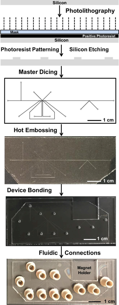
Microfluidic channels were hot embossed into 1.5 mm thick PMMA or 1 mm thick COP sheets using silicon masters according to the overall workflow described in Figure 1. To generate masters, 4” bare silicon wafers were spin coated with SPR220 photoresist (Dow Chemical, Midland, MI) and exposed to UV light (MA-6/BA-6 Mask and Bond Aligner, SUSS MicroTec, Garching, Germany) through the appropriate photomask. After a pre-development bake the wafers were developed using AZ726 metal ion free developer. Developed wafers were etched with deep reactive ion etching (STS Peagasus4, SPTS Technologies, Newport, UK) with etching gas, SF6, at 400 sccm; passivation layer gas, C2F6, at 200 sccm; for 100 ± 10 cycles; and 7 or 6 min. To remove the photoresist mask and residual polymer the etched wafers were cleaned using oxygen plasma: 800 sccm at 800 W and 150°C for 6 min (YES CV200RFS, Yield Engineering Systems, Livermore, CA). Cleaned wafers were then diced (ADT 7100 Dicing Saw, Advanced Dicing Technologies, Yokneam, Israel) to obtain the individual silicon masters. To reduce the feature roughness the diced masters were etched with 40% KOH at 70°C for 5 min. Before embossing, the silicon masters were ultrasonically cleaned for 10 min each using acetone, IPA and DI water, respectively.
Figure 1.
Device manufacturing in poly(methyl methacrylate) (PMMA) or cyclic olefin polymer (COP) through hot embossing using silicon masters fabricated by photolithography and deep reactive ion etching processes.
Hot embossing was performed on PMMA or COP using an in-house procedure. A 1.5 mm thick PMMA or 1 mm thick COP sample was aligned against the silicon master, and a glass slide was positioned on each side of the pair, followed by a copper plate for each side. This assembly was firmly clamped together with C-clamps (McMaster, Aurora, OH).46, 47 The complete clamp assembly was placed inside an oven (Thermo Scientific) at 135°C for 26 min for embossing, and at 90°C for 10 min followed by cooling to room temperature over 30 min to complete de-embossing.
For each embossed device, fluidic inlets (1.2 mm diameter) were drilled through another 2 mm thick PMMA sample using a CO2 laser cutter (Universal Laser Systems, Scottsdale, AZ) or 2 mm thick COP sample using the drill press (Cameron Micro Drill Presses, Sonora, CA). The position of these inlets complemented the channel geometry of the corresponding embossed sample. For the magnetic K-channel and integrated devices a rectangular slot was also cut in this layer to hold the permanent magnet. Drilled samples were flattened at 110°C for 26 min for PMMA and 20 min for COP in the oven using the clamping assembly mentioned above (but with no silicon template in the assembly).
PMMA layers were bonded using solvent-assisted low-temperature bonding48 and COP layers were bonded using the solvent-less high temperature bonding.46 Briefly, corresponding PMMA layers (the embossed channel portion and the drilled inlet portion) were bathed in ethanol for 10 min, dried, and aligned together in a clamping assembly as referenced above. Bonding occurred in the oven at 80°C for 1–2 h, and the exact processing time depends upon the total bonding area (device size). COP layers were bonded at 110°C for 20 min using the same procedure mentioned above but without using the ethanol/solvent bathing step. Bonded PMMA and COP device edges were sealed using acetonitrile and cyclohexane, respectively, as the solvents, and channels were thoroughly vacuum cleaned using isopropanol and DI water. Commercially available NanoPort interconnects (Idexx Corporation, Westbrook, ME) were attached to PMMA and COP using epoxy and cured overnight.
Device Characterization and Operation
The quality of the hot embossed channels was determined using scanning electron microscopy (SEM) imaging (LEO 1455VP, Carl Zeiss AG, Oberkochen, Germany), after sputtering a thin layer of gold (Cressington Scientific Instruments, Watford, UK) onto the devices. Channel quality was also verified with optical microscopy and flow-through of isopropanol and DI water prior to droplet experiments. Profilometry (Dektak XT, Bruker, Tucson, AZ) was also used to measure the embossed channel depth and uniformity.
To reduce dispersed phase surface wetting and to sustain stable droplet formation, the device channels of PMMA and COP devices were hydrophobically modified. Briefly, the channels were selectively exposed to UV light (Clearstone Technologies, Hopkins, MN) for 10 min by masking the non-channel regions with electrical tape. The exposed channels were treated with 10 mM heptadecafluoro-1,1,2,2-tetrahydrodecyltrichlorosilane diluted in FC 40 for 2 h at a flow rate of 2–5 μL/min. Devices were then cleaned using FC 40 for 30 min at 10 μL/min and DI water for 30 min at 20 μL/min. Modified device channels were then dried under vacuum for 30 min.
In all experiments, the carrier oil continuous phase was 2% Fluorosurfactant-008 in Novec 7500 Engineered Fluid. Water was the dispersed phase, except for experiments using suspensions of 10 μm diameter streptavidin coated magnetic microparticles (Sigma Aldrich, Milwaukee, WI) in optiprep density gradient medium (to reduce bead sedimentation). For picoinjector and K-channel injections, black dye or yellow dye (for contrast without obscuring beads in integrated devices) was injected. The continuous phase oil was flowed through the K-channel for magnetic bead enrichment during droplet splitting. For β-galactosidase assay, the streptavidin-magnetic beads were derivatized with biotin-β-galactosidase for 1 h, at 4°C in phosphate buffer saline (PBS), 0.5 % bovine serum albumin (BSA) at pH 7.4. After binding, the bead contents were thoroughly washed using PBS, 0.5 % BSA, pH 7.4 buffer, and the beads were re-suspended in optiprep solution for on-chip loading. Resorufin-β-D-galactopyranoside in PBS, 0.5 % BSA, pH 7.4 buffer was used as the substrate solution for the electrical K-channel injection.
A custom pressure-driven flow system supported by LabView (National Instruments, Austin, TX) was used to control the fluid flow through microchannels.15 Regulated N2 gas delivered to the headspace of sample vials forced fluid flow through 24 gauge Teflon tubing (Cole Palmer, Vernon Hills, IL) connected to the device through NanoPort interconnects, and flow rates for each solution were proportional to gas pressure. Typical applied pressures were from 10–40 kPa. An electric field (~40 VAC) was supplied by a custom DC to AC inverter to charge the 3 M NaCl in water-filled electrode channels.49 A magnetic field was applied with a stack of four 0.4T NdFeB (0.5” × 0.25” × 0.125”) permanent magnets placed inside the rectangular slot in the top PMMA and COP layers. Droplet microfluidic operations were recorded using a high-speed camera (VEO 640L, Vision Research, Inc., Wayne, NJ) connected to a DMi8 microscope (Leica Microsystems, Wetzlar, Germany). Fluorescent images for the β-galactosidase enzyme assay were collected using a Texas Red Filter Cube installed on the microscope. Data was analyzed using ImageJ software (National Institutes of Health, Bethesda, MD) to monitor droplet volume, droplet frequency, and magnetic bead position. Each experiment was repeated on at least three different devices from each design and all reported values include at least N = 25 droplets for each condition to demonstrate representative performance.
Results and Discussion
Device Manufacturing
Manufacturing devices with design complexity and channel dimensions comparable to PDMS is critical for adopting droplet microfluidic operations in thermoplastics. Initially, several materials were considered, including PMMA, COP, PC, and PP for this application. However, PMMA and COP were selected for their low cost, wide availability, and application-compatible physical properties (surface chemistry, optical window, and electromagnetic permittivity).40 Early attempts using laser engraved PMMA were unsatisfactory due to high channel roughness and poor control over channel depth and uniformity, and additionally, with COP, the material melting was an issue using the CO2 laser cutter. Even after post-process smoothing of PMMA channels, the devices could not support stable droplet operations. We then selected hot embossing, and established an in-house procedure to manufacture devices in PMMA and COP at lower set-up cost and reduced equipment requirements compared to injection molding.
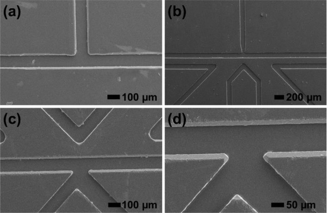
Silicon dioxide-silicon masters were originally fabricated using photolithography and wet etching techniques. Master fabrication worked well for simple, straight-channel designs; however, orientation-dependent over-etching interfered with more complex geometries.50 To overcome this problem, DRIE was successfully employed to generate isotropically etched features with high fidelity on silicon wafers. To reduce effects from scalloped features and surface roughness, which are associated with DRIE and could affect hot embossing yield, a 5 min KOH etching step was added that improved the de-molding yield of imprinted PMMA and COP. SEM imaging data in Figure 2 demonstrates the quality of imprinted T-junction, picoinjector, and K-channel features in PMMA. Profilometry measurements gave a feature height of 30 ± 4 μm for deep reactive ion etched silicon masters and channel depth of 29 ± 3 μm for hot embossed PMMA microchannel, with high embossing yield and uniform feature transfer. The observed small deviations in feature height and channel depth among templates is primarily due to the different number of cycles (100 ± 10 cycles) used for different instances of wafer processing using DRIE. Moreover, a small variation in hot embossed channel depth (33 ± 0.3 μm, n = 5 measurement locations) across a single device confirms uniform pressure application during the embossing procedure.
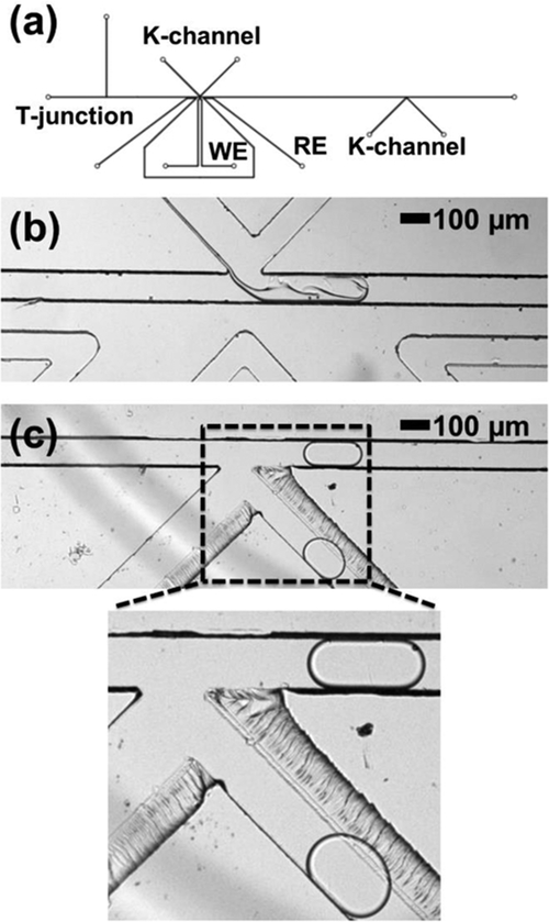
Figure 2.
Scanning electron micrographs of hot embossed droplet microfluidic device components in PMMA. (a) T-junction; (b) Picoinjector and (c) and (c) K-channel with working and reference electrodes.
Next, the inlet PMMA and COP layer was bonded to the imprinted channel layer. There are a variety of techniques that can be used for PMMA-PMMA bonding.51 Ultimately, thermal bonding above the glass transition temperature of PMMA proved challenging for maintaining the channel quality, so solvent-assisted bonding at low temperatures was used instead, whereas the high temperature bonding was used for the COP device fabrication. The resulting devices were all stable to at least 100 kPa of applied pressure. The channel smoothness and bonding worked well to support pressure-driven flow, as evidenced in the SEM, optical microscope, and solvent flow through studies. For reliable world-to-chip connections, commercially available microfluidic interconnects (Nanoports) were bonded to the devices with epoxy.
Wetting of PMMA and COP device channels by the aqueous phase interferes with stable droplet generation. Initially, plasma oxidation was used to modify the channel walls before reaction with heptadecafluoro-1,1,2,2-tetrahydrodecyltrichlorosilane to introduce a hydrophobic coating; however, unreliable oxygen plasma across the entire device footprint led to coating defects. To overcome this problem, UV-assisted activation of the channels46, 52 was used preceding treatment with heptadecafluoro-1,1,2,2-tetrahydrodecyltrichlorosilane suspended in FC 40. This surface modification procedure allowed for stable droplet generation and subsequent complex device operation, as described below.
Droplet generation using a T-junction
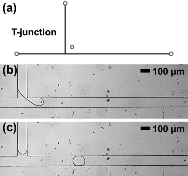
Droplet generation is the first step in most droplet microfluidic device operations, and, therefore, a commonly-used T-junction geometry (Figure 3a) was a first test objective for PMMA channels. As shown in Figure 3b and 3c, the water droplets suspended in fluorinated carrier oil were generated successfully. In this example, droplets had volumes of 330 ± 15 pL (n = 25 droplets) and were generated at 1.2 Hz frequency for further manipulation (see electronic supplementary information Video ES1), but changing flow conditions (i.e. applied pressures) could alter volume and frequency to desired parameters.
Figure 3.
(a) Device design for the T-junction droplet microfluidic operation in thermoplastic devices. (b) Droplet generation at a T-junction fabricated in PMMA via embossing. (c) Droplet flowing downstream of the T-junction down the main channel.
Reagent picoinjection
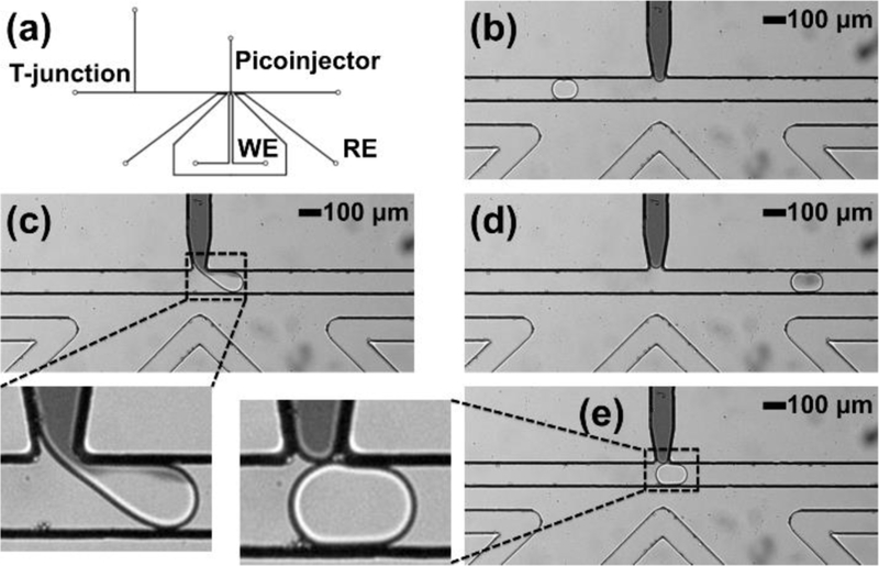
For adding reagents to pre-formed droplets to initiate in-droplet chemistry, direct injection advantageously does not require the added complexity of droplet train synchronization required by approaches that pair and fuse sample and reagent droplets.14, 17 One such geometry for direct injection, the picoinjector, uses an electro-pneumatic mechanism to force fluid into passing droplets at the picoinjector-droplet (aqueous-aqueous) interface in the presence of an electric field, which disturbs the boundary between the approaching droplet and the aqueous phase in the injector channel.14 The applied pressure on the picoinjected fluid determines the amount of fluid injected. This operation in thermoplastic devices requires the penetration of electric field through PMMA, supplied through saline-filled electrode channels in our device. Considering the electrical properties of PMMA and limitations of embossing channels in PMMA (feature size and spacing, etc.), a picoinjector device with 200 μm spacing between the boundary of the working electrode channel and the main droplet channel-picoinjector junction was designed (Figure 4a). To demonstrate picoinjector operation, we injected black dye into passing water droplets to enable visualization, as shown in Figure 4c (also see electronic supplementary information Video ES2). Figures 4b and 4d show the droplet before and after the picoinjection. In this device operation, 70 ± 10 pL (or 23%) black dye was successfully injected into the input droplets of 310 ± 10 pL, but changing picoinjector channel flow conditions (i.e. applied pressures) could alter the injected fluid volume. In the absence of electric field, the droplets do not interact and there is not dye (fluid) transfer, as shown in Figure 4e. Overall, this data demonstrates both effective electric field application and fabrication with sufficient fidelity to enable picoinjection in PMMA, a useful direct reagent injection operation in droplet microfluidics.
Figure 4.
Picoinjector operation in PMMA for reagent injection into droplets. (a) Picoinjector device design in thermoplastic material. (b) Droplet flowing down a channel before the picoinector. (c) Droplet immediately leaving the picoinjector in the presence of applied electric field and a zoomed image showing disruption of the droplet interface and exchange of fluid between the aqueous phases of the picoinjector and the droplet due to the applied electric field. (d) Droplet flowing down the main channel after picoinjection. (e) Droplet passing the picoinjector in the absence of applied electric field and a zoomed image showing no fluid exchange between the picoinjector and the passing droplet. WE: working electrode; RE: reference electrode.
Reagent injection using the multifunctional K-channel
Next, we tested the multifunctional K-channel design in reagent injection mode. This droplet manipulation scheme also relies on an electro-pneumatic direct injection mechanism, but stabilizes flow and reduces droplet-droplet cross-contamination by continuously flowing fresh reagent past the junction with the main channel.15 This device, shown in Figure 5a, included a K-channel structure instead of the picoinjector but was otherwise identical in critical features (channel length and cross-section, T-junction geometry, electrode channel structure, etc.). While a single K-channel device can be reconfigured between injecting reagents and extracting droplet volume, this first demonstration focused on electro-pneumatic fluid addition. Considering the K-channel architecture, there is an exchange of a small volume between the droplet and the K-channel; however overall there is a net volume that is injected into the droplet from the K-channel. This injected volume is calculated based upon the size difference between the droplet approaching K-channel and the one leaving K-channel. For effective reagent injection, black dye was flowed through the K-channel from narrow-to-wide channel size direction such that the black dye was injected into the water droplets, as shown in Figure 5c (also see electronic supplementary information Video ES3). Figures 5b and 5d show the droplet before and after the K-channel injection, respectively. In this device operation, 85 ± 20 pL (or 20%) black dye was successfully injected into input droplets of 415 ± 20 pL, but changing K-channel channel flow conditions (i.e. applied pressures) could alter the injected fluid volume or could also initiate the extraction of fluid volume from droplets. When an electric field is not applied, as shown in Figure 5e, there is no interaction between the K-channel aqueous phase and the passing droplet, and hence, no injection of dye into the droplet. Overall, the results from both picoinjector and K-channel operations not only fundamentally confirm that PMMA transmits sufficient electric field to enable electrically-mediated droplet processing, but also that PMMA does not intrinsically change the performance of higher order droplet functions.
Figure 5.
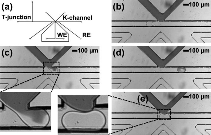
K-channel operation in PMMA for reagent injection into the droplet. (a) K-channel device design. (b) Flow of droplet in the main channel before K-channel injection. (c) Flow of droplet across the K-channel in the presence of applied electric field and zoomed image showing disruption of boundary and exchange of fluid between the aqueous phases of the K-channel and the droplet due to the applied electric field. (d) Flow of droplet in the main channel after K-channel injection. (e) Flow of droplet across the K-channel in the absence of applied electric field and zoomed image showing no fluid exchange between the K-channel and the passing droplet. WE: working electrode; RE: reference electrode.
Droplet splitting and magnetic bead enrichment using the multifunctional K-channel
The K-channel also supports another useful droplet operation: droplet splitting. Droplet splitting can not only parallelize a single reaction volume into two daughter volumes, but can also enrich magnetic beads into one daughter droplet when coupled with a local magnetic field. Therefore, sample associated with the magnetic bead (perhaps through antibody- or nucleotide sequence-based recognition and binding) is selectively concentrated in one daughter droplet, while the other daughter droplet can be discarded or otherwise manipulated. Therefore, this process can remove waste volume from a droplet while enriching bead-bound sample.15, 43, 44 For magnetic bead-containing droplet processing, this K-channel device was designed with 500 μm spacing between the main channel and the permanent magnet, as shown in Figure 6a. To optimize magnetic bead loading and counter bead sedimentation, droplets were formed from a suspension of magnetic beads in optiprep density gradient medium. In this example, fluorinated oil was flowed through the K-channel from wide-to-narrow channel size direction, and the applied pressure-dependent flow rate through this element selected the droplet splitting ratio. Importantly, as shown in Figure 6c, the daughter droplet in the main channel carried all the beads due to the presence of magnetic field, which pulled the beads to the lower boundary of the initial droplet prior to the splitting event (see electronic supplementary information Video ES4). The daughter droplet split into the K-channel outlet did not contain any beads. Figure 6b shows droplets before and after splitting in the main channel. In this device operation, 285 ± 30 pL (or 59 %) of the droplet volume was removed from 480 ± 15 pL input droplets along with the successful retention of all magnetic beads under these conditions, but increasing the proportion of the droplet removed increases the chance of bead loss. In contrast, in the absence of a magnetic field, the magnetic beads are randomly distributed within each droplet volume, as shown in Figure 6d where they are found in both fractions of the split input droplet. This result further demonstrates the compatibility of PMMA thermoplastic devices with established droplet operations in the context of droplet splitting and magnetic field permeation.
Figure 6.
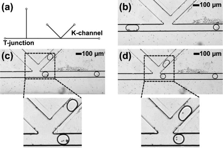
K-channel operation in PMMA for droplet splitting and magnetic bead concentration. (a) K-channel device design. (b) Flow of droplets in the main channel before and after splitting using a K-channel (c) Droplet immediately after splitting at the K-channel in the presence of applied magnetic field and zoomed image of split droplets with magnetic concentration of beads in the main channel and an empty droplet in the K-channel. (d) Droplet splitting at the K-channel in the absence of applied magnetic field and zoomed image showing no magnetic concentration: both droplets contain magnetic beads.
Multi-step droplet processing using thermoplastic microfluidics: Integrated droplet generation, reagent injection, and magnetic bead enrichment
As a next demonstration to establish the ability of thermoplastic microfluidic devices to support higher-order component integration for multi-step sample processing, droplet generation, electrical K-channel injection, and magnetic K-channel droplet splitting operations were performed sequentially on a single device, as shown in Figure 7a. Magnetic bead-containing optiprep-in-oil droplets were first generated at the T-junction, followed by injection of dye at the first K-channel, as shown in Figure 7b. At the second K-channel the magnetic splitting operation collected magnetic beads in the main channel daughter droplet only (Figure 7c). A zoomed in image provides a closer view of the droplet splitting to show the final position of captured magnetic beads. In this integrated device, input droplets of 755 ± 30 pL size were first injected with 375 ± 35 pL of dye solution (a 50 % volume increase), followed by the removal of a total of 525 ± 30 pL (a 46 % reduction in droplet volume) via droplet splitting (see electronic supplementary information Video ES5). A small fabrication defect can be seen in the second K-channel; however, this defect did not significantly affect the droplet manipulation as can be seen through the droplet movement in the supplementary information video ES5. By including formation, injection, and magnetic enrichment components in series, this device washes the beads in the droplets, exchanging the droplet fluid composition while retaining the bead sample. While a proof-of-concept experiment, combining serial modules encompassing both electric and magnetic field components clearly demonstrates the ability of PMMA thermoplastic microfluidic devices made via hot embossing to support multi-step droplet processing capabilities with equivalent performance to conventional PDMS devices.
Figure 7.
Integrated device operation in PMMA for droplet generation, injection, and magnetic splitting. (a) Device design for the integrated device. (b) Dilute dye injection at K-channel in the presence of applied electric field. (c) Droplet splitting at K-channel and magnetic concentration in the presence of applied magnetic field and zoomed image showing the droplet containing magnetic beads in the main channel and the empty droplet in the K-channel. WE: working electrode; RE: reference electrode.
As a final demonstration, the integrated washing device was utilized to perform a simple in-droplet enzymatic activity and sampling assay. For this application, the material system was changed to COP (brightfield images of the integrated COP device is shown in Figure ES1). All basic device functions were identical in performance to PMMA, as previously described. For this demonstration, biotinylated β-galactosidase was captured on the surface of streptavidin-coated magnetic beads, then loaded the enzyme-functionalized beads into droplets in the integrated COP device. Upon substrate injection at the first K-channel (resorufin-β-D-galactopyranoside), the enzyme reaction was initiated. Figures 8a-b show low background fluorescence from substrate and bead samples prior to injection, but fluorescent resorufin product immediately formed upon injection, as evidenced from weak fluorescence localized near the beads in panel 8c. After ~2.6 s reaction time in the channel, Figure 8d shows a significant increase in fluorescence both near enzyme-coated beads and delocalized throughout the droplet, indicating reaction progress. Finally, K-channel splitting samples a portion of the product for immediate collection at this time point, and bead-bound enzyme was retained in the main channel portion by local magnetic field for additional reaction or other processing. With this proof-of-concept experiment, combining both electric and magnetic field components to process an in-droplet enzymatic process, the amenability of thermoplastic microfluidic devices for droplet-based, multi-step (bio)chemical assays.
Figure 8.
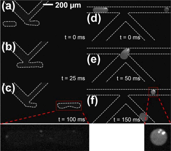
Fluorescence imaging of the in-droplet β-galactosidase enzymatic assay in integrated microfluidic devices manufactured in cyclic olefin polymer (COP). (a) Droplets loaded with biotinylated-β-galactosidase bound to streptavidin coated magnetic beads approach the substrate injection K-channel showing very low background fluorescence. (b) K-channel-mediated resorufin-β-D-galactopyranoside substrate injection in the presence of applied electric field initiates the chemical reaction. (c) Immediately after injection, weak fluorescence localized near magnetic beads indicates initial formation of fluorescent resorufin product (see expanded inset). (d) Downstream imaging after ~2.6 s incubation demonstrates additional product formation and mixing throughout the droplet. (e) Droplet splitting at the K-channel localizes magnetic-bead bound enzymes in the main channel portion. (f) After splitting, the magnetic-bead bound enzyme remains in the main channel for additional reaction or downstream processing (see expanded inset), while the K-channel collects a portion of the product.
Conclusions
We have reported a fabrication workflow to manufacture droplet microfluidic devices in thermoplastics and have demonstrated successful operation of several key droplet manipulation operations. Photolithography followed by deep reactive ion etching was used to fabricate silicon masters that facilitated high performance hot embossing. This approach was utilized to create individual microfluidic components supporting droplet generation at a T-junction, reagent injection using both picoinjector and K-channel designs, and volume removal and magnetic bead enrichment using the K-channel. In addition to demonstrating the compatibility of PMMA and COP thermoplastic for droplet microfluidics in terms of channel size and surface properties, these devices also showed that electric and magnetic field-based droplet actuation can be achieved comparably to devices in PDMS. This work is the first to report multi-step droplet manipulations in thermoplastics and therefore lays the groundwork for the translation of droplet microfluidic devices from PDMS-based prototypes into materials systems that are poised for mass production.
Supplementary Material
Acknowledgments
We gratefully acknowledge the National Institutes of Health (Grant No. CA191186) for supporting this work. SRD acknowledges support from the National Science Foundation Graduate Research Fellowship Program. Support from the University of Michigan’s Lurie Nanofabrication Facility and University of Michigan College of Literature, Science, and the Arts Machine Shop is greatly appreciated. We also thank Professors Adam Matzger and Robert Kennedy for providing access to the CO2 laser cutter and drill press, respectively.
References
- 1.Kaminski TS and Garstecki P, Chemical Society Reviews, 2017, 46, 6210–6226. [DOI] [PubMed] [Google Scholar]
- 2.Shang LR, Cheng Y and Zhao YJ, Chemical Reviews, 2017, 117, 7964–8040. [DOI] [PubMed] [Google Scholar]
- 3.Guo MT, Rotem A, Heyman JA and Weitz DA, Lab on a Chip, 2012, 12, 2146–2155. [DOI] [PubMed] [Google Scholar]
- 4.Theberge AB, Courtois F, Schaerli Y, Fischlechner M, Abell C, Hollfelder F and Huck WTS, Angewandte Chemie-International Edition, 2010, 49, 5846–5868. [DOI] [PubMed] [Google Scholar]
- 5.Shahi P, Kim SC, Haliburton JR, Gartner ZJ and Abate AR, Scientific Reports, 2017, 7. [DOI] [PMC free article] [PubMed] [Google Scholar]
- 6.Lan F, Demaree B, Ahmed N and Abate AR, Nature Biotechnology, 2017, 35, 640-+. [DOI] [PMC free article] [PubMed] [Google Scholar]
- 7.Xu Y, Lee J-H, Li Z, Wang L, Ordog T and Bailey R. C. J. L. o. a. C., 2018.
- 8.Guetschow ED, Steyer DJ and Kennedy RT, Analytical Chemistry, 2014, 86, 10373–10379. [DOI] [PMC free article] [PubMed] [Google Scholar]
- 9.Guetschow ED, Kumar S, Lombard DB and Kennedy RT, Analytical and Bioanalytical Chemistry, 2016, 408, 721–731. [DOI] [PMC free article] [PubMed] [Google Scholar]
- 10.Price AK, MacConnell AB and Paegel BM, Analytical Chemistry, 2016, 88, 2904–2911. [DOI] [PMC free article] [PubMed] [Google Scholar]
- 11.Schaerli Y, Wootton RC, Robinson T, Stein V, Dunsby C, Neil MAA, French PMW, deMello AJ, Abell C and Hollfelder F, Analytical Chemistry, 2009, 81, 302–306. [DOI] [PubMed] [Google Scholar]
- 12.Xu JH, Li SW, Tan J, Wang YJ and Luo GS, Aiche Journal, 2006, 52, 3005–3010. [Google Scholar]
- 13.Garstecki P, Stone HA and Whitesides GM, Physical Review Letters, 2005, 94. [DOI] [PubMed] [Google Scholar]
- 14.Abate AR, Hung T, Mary P, Agresti JJ and Weitz DA, Proceedings of the National Academy of Sciences of the United States of America, 2010, 107, 19163–19166. [DOI] [PMC free article] [PubMed] [Google Scholar]
- 15.Doonan SR and Bailey RC, Analytical Chemistry, 2017, 89, 4091–4099. [DOI] [PMC free article] [PubMed] [Google Scholar]
- 16.Frenz L, Blank K, Brouzes E and Griffiths AD, Lab on a Chip, 2009, 9, 1344–1348. [DOI] [PMC free article] [PubMed] [Google Scholar]
- 17.Lee M, Collins JW, Aubrecht DM, Sperling RA, Solomon L, Ha JW, Yi GR, Weitz DA and Manoharan VN, Lab on a Chip, 2014, 14, 509–513. [DOI] [PubMed] [Google Scholar]
- 18.Akartuna I, Aubrecht DM, Kodger TE and Weitz DA, Lab on a Chip, 2015, 15, 1140–1144. [DOI] [PubMed] [Google Scholar]
- 19.Ahn K, Kerbage C, Hunt TP, Westervelt RM, Link DR and Weitz DA, Applied Physics Letters, 2006, 88. [Google Scholar]
- 20.Mazutis L, Gilbert J, Ung WL, Weitz DA, Griffiths AD and Heyman JA, Nature Protocols, 2013, 8, 870–891. [DOI] [PMC free article] [PubMed] [Google Scholar]
- 21.Sung YJ, Kim JYH, Choi HI, Kwak HS and Sim SJ, Scientific Reports, 2017, 7. [DOI] [PMC free article] [PubMed] [Google Scholar]
- 22.Tice JD, Song H, Lyon AD and Ismagilov RF, Langmuir, 2003, 19, 9127–9133. [Google Scholar]
- 23.Thorsen T, Roberts RW, Arnold FH and Quake SR, Physical Review Letters, 2001, 86, 4163–4166. [DOI] [PubMed] [Google Scholar]
- 24.Nisisako T, Torii T and Higuchi T, Lab on a Chip, 2002, 2, 24–26. [DOI] [PubMed] [Google Scholar]
- 25.Xu JH, Luo GS, Li SW and Chen GG, Lab on a Chip, 2006, 6, 131–136. [DOI] [PubMed] [Google Scholar]
- 26.McDonald JC and Whitesides GM, Accounts of Chemical Research, 2002, 35, 491–499. [DOI] [PubMed] [Google Scholar]
- 27.Duffy DC, McDonald JC, Schueller OJA and Whitesides GM, Analytical Chemistry, 1998, 70, 4974–4984. [DOI] [PubMed] [Google Scholar]
- 28.Rotem A, Ram O, Shoresh N, Sperling RA, Goren A, Weitz DA and Bernstein BE, Nature Biotechnology, 2015, 33, 1165–U1191. [DOI] [PMC free article] [PubMed] [Google Scholar]
- 29.Lee JN, Park C and Whitesides GM, Analytical Chemistry, 2003, 75, 6544–6554. [DOI] [PubMed] [Google Scholar]
- 30.Bodas D and Khan-Malek C, Sensors and Actuators B-Chemical, 2007, 123, 368–373. [Google Scholar]
- 31.Sahore V and Fritsch I, Analytical Chemistry, 2013, 85, 11809–11816. [DOI] [PubMed] [Google Scholar]
- 32.Gerhardt RF, Peretzki AJ, Piendl SK and Belder D, Analytical Chemistry, 2017, 89, 13030–13037. [DOI] [PubMed] [Google Scholar]
- 33.Becker H and Gartner C, Microchip Diagnostics: Methods and Protocols, 2017, 1547, 3–21. [DOI] [PubMed] [Google Scholar]
- 34.Wang SC, Lee CY and Chen HP, Journal of Chromatography A, 2006, 1111, 252–257. [DOI] [PubMed] [Google Scholar]
- 35.Becker H and Heim U, Sensors and Actuators a-Physical, 2000, 83, 130–135. [Google Scholar]
- 36.Attia UM, Marson S and Alcock JR, Microfluidics and Nanofluidics, 2009, 7, 1–28. [Google Scholar]
- 37.Wang ZK, Zheng HY, Lim RYH, Wang ZF and Lam YC, Journal of Micromechanics and Microengineering, 2011, 21. [Google Scholar]
- 38.Mair DA, Geiger E, Pisano AP, Frechet JMJ and Svec F, Lab on a Chip, 2006, 6, 1346–1354. [DOI] [PubMed] [Google Scholar]
- 39.Esch MB, Kapur S, Irizarry G and Genova V, Lab on a Chip, 2003, 3, 121–127. [DOI] [PubMed] [Google Scholar]
- 40.Nge PN, Rogers CI and Woolley AT, Chemical Reviews, 2013, 113, 2550–2583. [DOI] [PMC free article] [PubMed] [Google Scholar]
- 41.Subramanian B, Kim N, Lee W, Spivak DA, Nikitopoulos DE, McCarley RL and Soper SA, Langmuir, 2011, 27, 7949–7957. [DOI] [PMC free article] [PubMed] [Google Scholar]
- 42.Hwang SJ, Tseng MC, Shu JR and Yu HH, Surface & Coatings Technology, 2008, 202, 3669–3674. [Google Scholar]
- 43.Verbruggen B, Toth T, Cornaglia M, Puers R, Gijs MAM and Lammertyn J, Microfluidics and Nanofluidics, 2015, 18, 91–102. [Google Scholar]
- 44.Brouzes E, Kruse T, Kimmerling R and Strey HH, Lab on a Chip, 2015, 15, 908–919. [DOI] [PMC free article] [PubMed] [Google Scholar]
- 45.Tan YC, Fisher JS, Lee AI, Cristini V and Lee AP, Lab on a Chip, 2004, 4, 292–298. [DOI] [PubMed] [Google Scholar]
- 46.Sahore V, Sonker M, Nielsen AV, Knob R, Kumar S and Woolley AT, Analytical and Bioanalytical Chemistry, 2018, 410, 933–941. [DOI] [PMC free article] [PubMed] [Google Scholar]
- 47.Sonker M, Parker EK, Nielsen AV, Sahore V and Woolley AT, Analyst, 2018, 143, 224–231. [DOI] [PMC free article] [PubMed] [Google Scholar]
- 48.Ling N, Lee JS and Lee NY, Sensors and Actuators a- Physical, 2017, 265, 168–173. [Google Scholar]
- 49.Sciambi A and Abate AR, Lab on a Chip, 2014, 14, 2605–2609. [DOI] [PMC free article] [PubMed] [Google Scholar]
- 50.Seidel H, Csepregi L, Heuberger A and Baumgartel H, Journal of the Electrochemical Society, 1990, 137, 3612–3626. [Google Scholar]
- 51.Tsao CW and DeVoe DL, Microfluidics and Nanofluidics, 2009, 6, 1–16. [Google Scholar]
- 52.Sun XH, Yang WC, Pan T and Woolley AT, Analytical Chemistry, 2008, 80, 5126–5130. [DOI] [PMC free article] [PubMed] [Google Scholar]
Associated Data
This section collects any data citations, data availability statements, or supplementary materials included in this article.


