Abstract
Finger impairment following stroke results in significant deficits in hand manipulation and the performance of everyday tasks. While recent advances in rehabilitation robotics have shown promise for facilitating functional improvement, it remains unclear how best to employ these devices to maximize benefits. Current devices for the hand, however, lack the capacity to fully explore the space of possible training paradigms. Particularly, they cannot provide the independent joint control and levels of velocity and torque required. To fill this need, we have developed a prototype for one digit, the cable actuated finger exoskeleton (CAFE), a three-degree-of-freedom robotic exoskeleton for the index finger. This paper presents the design and development of the CAFE, with performance testing results.
Keywords: Cable actuated finger exoskeleton (CAFE), hand rehabilitation, robot-assisted rehabilitation system
I. Introduction
PRECISE Anger and thumb interactions are fundamental to human motor control. These movements are used constantly in everyday tasks. Neurological disorders such as stroke greatly impair this core function [1], [2] directly impacting quality of life [3].
Stroke is the leading cause of serious, long-term disability in the United States [4]. Out of an estimated 6.4 million stroke survivors in the U.S. [5], 30% will require ongoing care or experience chronic impairment [4], [5]. The economic costs of stroke exceeded $73 billion for 2010 in the U.S. alone [5], [6].
Thus, current research focuses on improving the efficacy of rehabilitation. Recent studies have shown that repetitive practice of desired movement leads to promising recovery. For example, promotion of use of the paretic upper limb through the constraint-induced therapy has led to improved motor control [7]–[9]. This practice has been shown to improve plasticity and incite cortical functional reorganization leading to improved motor control following stroke [10], [11].
Because of the complexity of the hand, with 21 mechanical degrees-of-freedom (DoF) and even more muscles, and the need for lengthy and consistent repetition of movement, researchers have begun to implement robotics for rehabilitation. Robot-assisted rehabilitation has been demonstrated to enable longer training sessions while reducing the workload on therapists [12].
In the past decade, a number of devices have been developed expressly for, or applied to, hand rehabilitation. These include both commercial products, such as CyberGrasp (Immersion Corporation, San Jose, CA) [13], the Hand Mentor (Kinetic Muscles, Inc., Tempe, AZ), and the Amadeo System (Tyromotion GmbH, Graz, Austria) and experimental devices, including HEXORR [14] Rutgers Master II-ND [15], HWARD [16], HandCARE [17], HANDEXOS [18], and others [19]–[25].
A fundamental question, however, is how to best use these devices for rehabilitation. The extent to which rehabilitation robots should assist, resist or otherwise alter movement of the user is unclear and requires further study. Unfortunately, existing devices do not provide the complete range of speed, force, and independence of joint control to thoroughly explore the space of different training algorithms and environments. For example, stroke survivors may generate substantial coactivation, especially during intended finger extension [26], such that significant joint torques may need to be provided by the assistive device to overcome the misapplied joint torques of the user. Abnormalities in impedance and motor control may vary from joint to joint such that independent control of each joint through the exoskeleton may be beneficial for training. Additionally, to examine and mitigate power deficits [27] and peak tracking limitations, high joint rotational velocity may be needed that would be consistent with human physiological capabilities.
A device possessing these capabilities would greatly facilitate the scientific investigation of hand function and the therapy following stroke. In accordance with these goals, we have developed a prototype for a single finger. The cable actuated finger exoskeleton (CAFE), presented here, will improve on current rehabilitation robotics solutions by providing a versatile framework with high performance, real-time control, individual actuation of each of the finger joints, and forces and speeds comparable to normal human function. The CAFE will allow for normal task execution enabling direct comparisons between distinct rehabilitation strategies and motor control studies within a single platform.
The CAFE concept and design originated at the Rehabilitation Institute of Chicago. It is developed with the support of rehabilitation therapists to reflect the best practices and lessons learned from numerous other devices, and to improve usability and wearability. However, the device is intended for research investigations and not for regular therapeutic use. This paper describes the CAFE with a basic controller and analyzes preliminary kinematic and torque control performance.
II. Finger Exoskeleton Design
A. Design Requirements
To enable the exploration of rehabilitation and motor control strategies of the finger, the CAFE must satisfy several design criteria. A device meeting these criteria would enable detailed analysis of index finger control through interaction with its joints across the range of dynamic movements.
First, the exoskeleton must be biomechanically compatible with an individual’s natural joint rotation and provide independent actuation of each of the joints of the finger. In order to implement the rehabilitation training algorithms and create natural joint rotation for the affected finger, it is necessary to provide individual actuation for each of the finger joints, as alterations in impedance and motor control may vary from joint to joint following stroke.
Next, to reduce impedance of normal movement, the exoskeleton must be lightweight, have low inertia and a relatively small profile with respect to the index finger.
Third, for application to practical finger manipulation tasks, the device must support peak angular velocities on the order of 10007s [28], representative of the speeds we have observed in normal movements. This speed requirement is also necessary for the study of sensory perception as the finger movement ranges from low to high speed. similarly, requirements for maximum sustained torques were set to 2.0, 0.75, and 0.25 N∙m at the metacarpophalangeal (MCP), proximal interphalangeal (PIP), and distal interphalangeal (DIP) joints, respectively. These values, equaling roughly half of the average maximal torque found in normal individuals (unpublished data), are sufficient to overcome the unwanted flexion torques that can be unintentionally generated by stroke survivors due to excessive coactivation of finger flexor muscles during task performance [29] as well as passive stiffness and damping in the finger [29], [30].
Finally, to control finger manipulation tasks, the CAFE must support both position and the torque control at each joint. Thus, both joint angle and torque measurements are required for feedback control and for data collection.
From these requirements, the exoskeleton was designed, fabricated, actuated, and instrumented as described in the following sections.
B. Mechanical Structure
To achieve biomechanical compatibility with an individual’s natural joint rotation, the rotational movement of the device must match that of the digit. While this can be achieved with a remote center of rotation (CoR) [19], [21], [31]–[33], the most direct means is to align the joints of the device with the rotational axes of the user’s finger, avoiding off axis forces and moments that would otherwise be present. In the CAFE, this is achieved with a planar, serially segmented exoskeleton (see Fig. 1) that runs along the radial side of the index finger (see Fig. 2). We assume static centers of rotation for each joint as is commonly accepted in the literature [14], [34], [35]. The three rotational joints of the exoskeleton are aligned with the flexion/extension axes of the MCP, PIP, and DIP joints (see Fig. 2), with a fixed MCP abduction–adduction joint. Pairs of parallel bars connect the structure to the proximal, middle, and distal segments of the finger. Rotation of the exoskeleton produces approximately equivalent rotation of the finger joint across large ranges of motion: −15–75°, 0–90°, and 0–90° for the MCP, PIP, and DIP joints, respectively.
Fig. 1.
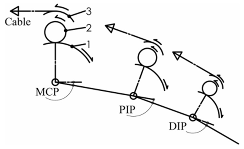
Three-link, planar model of CAFE. Transmission components are shown as arcs including: (1) the joint concentric gear, (2) small mating gear, and (3) joint pulley. Respective motions are indicated via arrows as an example of creating flexion at each joint.
Fig. 2.
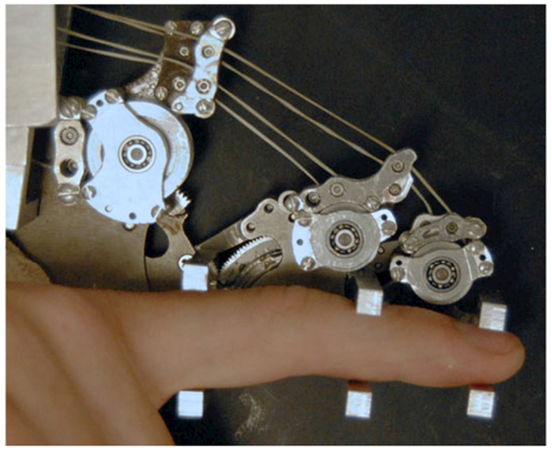
CAFE located on radial side of the index finger with parallel bars interfacing with each finger segment. Transmission pulleys above the corresponding joint transmit force from the appropriate cable to the target joint. Guide pulleys direct cables over each joint toward distal targets.
For application across users, the CAFE must be able to accommodate finger segments of different lengths and thicknesses while maintaining a proper alignment. This is achieved through interchangeable linkages connecting each joint of the exoskeleton. A set of linkages have been fabricated for each joint so that the appropriate linkage can be matched to the finger. The contact rod brackets are sized to accommodate a wide range of the population, with shims for adjustment between users.
To reduce impedance and inertia, the mass of the exoskeleton was minimized. All components were fabricated from aluminum or steel as necessary to withstand the relatively high torques required of the device. The complete portion of the exoskeleton that actually moves with the finger has a mass of 138 g. Physical dimensions were minimized wherever possible while maintaining mechanical rigidity and safety for the wearer. The maximum width of the structure along the finger is only 8 mm. The rotational inertia of each joint is estimated as 108, 53, and 0.46 kg/mm2 for the MCP, PIP, and DIP, respectively.
Thrust bearings at the MCP and PIP joints serve to accommodate potentially significant off-axis moments. Mechanical stops limit the range of motion of each joint to prevent accidental injury. These stops can be adjusted to match the passive range of motion of the user.
The complete exoskeleton is attached to a plate on a fiberglass cast that encases the wrist, and thus maintains its posture (see Fig. 3) and prevents slip between the user and CAFE. The device is externally supported to remove weight from the forearm of the user [36].
Fig. 3.
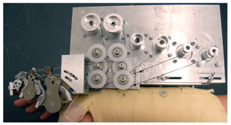
CAFE attached to mounting plate on forearm cast. CAFE joints, left to right: DIP, PIP, MCP. The motor plate supports three motor pairs and is adjustable with slots for accurate translational placement of the MCP joint.
C. Actuation
To achieve independent movement/torque production at each joint, separate actuators are employed at each joint of the CAFE. DC servomotors were chosen due to their performance in all four quadrants of the torque–velocity space. To maximize backdrivability, gearless motors were selected that could meet the requirements of joint angular velocities on the order of 1000°/s and sustained joint torques of 2.0, 0.75, and 0.25 N∙m at the MCP, PIP, and DIP joints, respectively. Specifically, AKM motors (Kollmorgen, Munkekullen, Sweden) are being used, with AKM13 C, AKM12C, and AKM11C for the MCP, PIP, and DIP joints, with inertias 4.5, 3.1, and 1.7 kg/mm2, respectively.
In order to reduce the added mass on the hand, the dc motors are located on the forearm. Cables (Spectra kite line) transmit motor torque to the exoskeleton joints. The cable drive design reduces friction and backlash in comparison with standard transmissions, thereby allowing the motors to be located a significant distance from the joints. Cable transmissions have been successfully implemented in commercial robots such as the Phantom (SensAble Technologies, Woburn, MA) and WAM (Barrett Technologies, Cambridge, MA). As these cables can only pull, similar to muscles, two cables, and thus two motors are used for each joint for a total of six cables and motors (see Fig. 3).
Primary gear reduction from motor cable to exoskeleton joint occurs directly at the joint. Namely, the cables are connected to pulleys that subsequently drive a section of a gear fixed to a rotating segment of the exoskeleton (see Figs.1–3). This gear reduction directly at the joint reduces the tension in the cables from the motors, thereby providing as much bandwidth for control as possible [37]. Total reduction is 11.8, 3.7, and 1.4 at the MCP, PIP, and DIP joints, respectively. A set of bearing and pulley cable guides leads each cable across more proximal joints to its proper transmission pulley, as necessary.
D. Sensing
Joint angles are computed from the motor shaft rotations, as measured from optical encoders (2000 counts per revolution, Kollmorgen) integrated into each motor. Motor shaft rotation is converted to joint rotation through consideration of the pulley and gear reduction between the motor and the joint.
Joint torque is computed from the contact forces measured at each finger segment. The custom contact rods consist of two horizontal beams, one above and one below the user’s digit (see Fig. 2). Each aluminum beam is configured with four strain gauges (SGT-1/350-TY13, Omega, Stamford, CT) oriented at 45° from the principle bending axis of the beam and connected in a full Wheatstone bridge (see Fig. 4). This strain gauge configuration rejects the bending moment and measures only the perpendicular shear force in the beam [38], allowing for an accurate contact force measurement regardless of finger size, contact location, perpendicular shear forces or off axis moments. The signal from the Wheatstone bridge is amplified by a gain of 1000 and low-pass filtered at 400 Hz, before input to the controller.
Fig. 4.
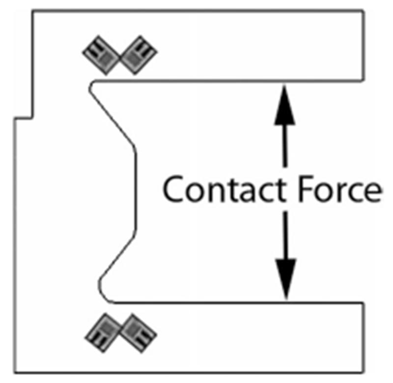
Schematic of the finger contact rods with strain gauges. In this configuration, 45° from the neutral axis, the gauges reject the bending moment and transduce the precise normal contact force.
III. Control System
Control of either position or torque can be implemented at each joint.
A. Joint Position Control
The joint position controller is responsible for executing the target joint trajectory in an accurate manner.
At each joint, two cables act on the joint pulley in opposite directions, one for flexion and one for extension. These agonist–antagonist cables must be adjusted simultaneously to achieve the desired torque differential to actuate the joint. Critically, tension must be maintained in both cables to keep either from going slack.
At the lowest level, the motors are driven by motor amplifiers (S200, Kollmorgen) that operate in a torque servo mode. An analog signal from the controller is sent to the amplifier to set the target torque. In this fashion, a baseline torque can be maintained for tension and an additional torque may be added to instigate movement.
In this configuration, one motor is selected as the driving motor and the other is selected as the following motor by a conditional logic block (designated as Planner in Fig. 5) in the controller. For example, if a net flexion is desired, the motor providing flexion joint rotation is designated by the planner as the driving motor and the motor providing extension is designated as the following motor. The driving motor will always provide the torque required to change the joint angle while the following motor will provide just enough torque to maintain nominal cable tension.
Fig. 5.
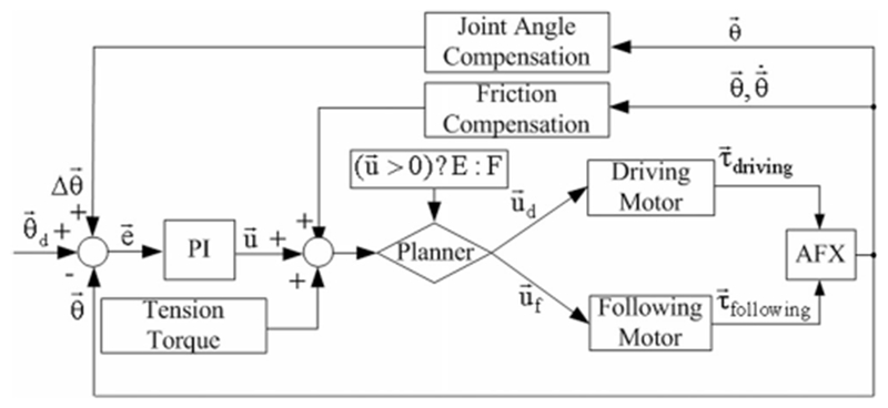
PI angular position controller for a single joint including compensation and baseline torque to maintain cable tension. The driving and following motors are selected by the Planner based on the control command .
PI parameters of the controller (see Fig. 5) were tuned based on Ziegler–Nichols with subsequent heuristic methodology to achieve a 30° angular step with a critically damped response and settling time below 100 ms under no external resistance.
Joint angle is computed from the signals from the quadrature encoders at the motor shafts. Each motor in the pair for a given joint independently tracks joint angle, wherein for a given movement of the joint, one encoder will increase and the opposing encoder will decrease. The differential between two encoder values is then divided by two and taken as the actual angle of the joint.
Due to the physical nature of the device, this differential angle measurement is not perfect. The cables for the distal joints, PIP and DIP, must first cross the more proximal joint(s). The length of each cable will be affected by the motion of the joint(s) it crosses. As the routing of each cable varies slightly, the impact of joint rotation on cable length will differ for each cable. Thus, a linear mapping of joint angles to cable length is experimentally measured by fixing distal joints, rotating proximal joints and measuring joint angle deviations (see Table 1). This linear relationship uses changes in proximal joint angle to update the measured angle of distal joints based on a scaling factor (r; (1)) to actively compensate for the discrepancies in cable routing
| (1) |
TABLE I.
Distal Joint Compensation
| PIP/MCP | DIP/MCP | DIP/PIP |
|---|---|---|
| 0.050 | 0.093 | 0.055 |
Compensation values are calibrated based on the proximal joint angle.
To improve the performance at the onset of movement, static friction compensation is integrated into the controller. The compensation block (see Fig. 5) is a function of position error and current velocity, calibrated experimentally to counteract static friction across different postures of the device, effective when the velocity is less than 6°/s (static) and the position error is greater than 1°. In this framework, the compensatory block produces peak outputs of 0.2, 0.05, and 0.01 N∙m at each of the MCP, PIP, and DIP joints only when the robot has position error but is not moving or is moving very slowly.
B. Joint Torque Control
A torque controller with separately tuned PI loops, feed forward, and torque compensation was developed for all three joints (see Fig. 6). The feedback signal for each loop is the joint torque calculated from the contact force measured by the strain gauge of the parallel bar brackets. As the contact rods reside at a fixed distance from the preceding joint, the net torque may be computed from the measured force. This PI controller is tuned in the same manner as the angular controller to achieve a 20-N force on the contact bars with a rise time around 50 ms.
Fig. 6.
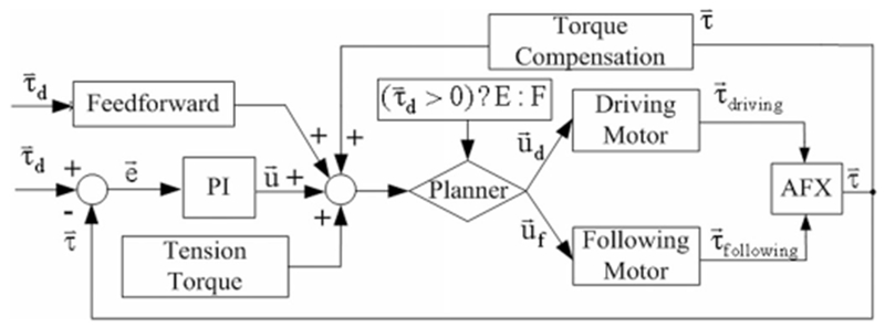
PI torque controller for a single joint. The driving and following motors are selected by the Planner according to the desired torque. The appropriate feedback signal from the CAFE contact rods (extension or flexion) is also selected to match the driving motor.
As with position control, a planner again selects the driving and following motors based on the intended torque direction. One motor provides the flexion torque while the other creates the extension torque. Similarly, one beam from each bracket measures the flexion contact force while the other beam measures the extension contact force.
For the open-link chain configuration of the exoskeleton, torque production at more distal joints requires identical compensation at more proximal joints. Torque compensation (see Fig. 6) was instituted to deliver these torques to the more proximal joints without the effort of the PI controller.
A Feedforward system (see Fig. 6) is implemented to reduce delay and achieve rapid-onset torques as might be required for perturbation experiments. This system is proportionally based on the desired output torque and experimentally calibrated to activate the motor and achieve 75% of the desired output torque (2). This level of feedforward torque minimizes perturbation delay without generating unstable oscillations that emerge at higher values
| (2) |
C. Real-Time Control Implementation
The control system of the finger exoskeleton is implemented using the MATLAB xPC Target. The xPC Target is a real-time kernel that runs on an independent computer allowing for real-time control. Executable code is loaded onto this target PC from the host PC running MATLAB Simulink software [39]. The data signals are acquired in real time by the target PC and uploaded to the host PC over a direct crossover Ethernet cable. The experimenter monitors the signal data and tunes the model parameters on the host computer (see Fig. 7).
Fig. 7.
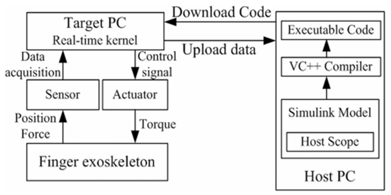
Real-time control system using xPC Target. The host PC manages the control program, visual feedback, and data storage; the target PC runs the real-time control and acquires sensor data.
A PCI-6220 ADC board (National Instruments, Austin, TX) is installed on the target PC to perform analog-digital conversion of the signals from the force sensors. The CNT32–8M encoder board (CONTEC, Sunnyvale, CA) records the digital encoder signals and the PCI-6703 DAC board (National Instruments) converts digital command signals into the analog signals that drive the motor amplifiers. All signals are sampled at 10 kHz.
D. Safety Consideration
For safety, an overdamped or critically damped behavior in the joint angle control is preferred to an underdamped system to prevent injury from joint hyperextension. A derivative term, which would minimize velocity and help prevent hyperextension, was not incorporated in the controller as it would amplify the noise on the feedback signal, thereby resulting in instability. We can assume that the dampened behavior will increase with the eventual introduction of a finger to the device, as the passive properties of the finger will impede movement [30], thus assuring user safety. Joint angles and torques are continuously monitored by the control program to ensure that predefined limits are not exceeded.
Mechanically, guide slots restrict the range of motion of each joint and can be adjusted to limit joint range as needed. In this design, differently sized motors are used for each joint. In this manner, the peak motor torque is well matched to the peak voluntary subject torque and the potential for excessive torque is minimized. An emergency switch immediately terminates all power to the motors.
IV. Performance Testing
Experiments were designed to test the performance of the CAFE, including kinematic control performance and force control performance without a human finger in the device.
A. Testing of Kinematic Control Performance
A two-camera setup employing high-resolution, monochrome CCD cameras (IPX-1M48, Imperx, Inc., Boca Raton, FL) was employed to examine kinematic performance of the CAFE. The cameras were used to measure exoskeleton joint angles for comparison with encoder measured angles. Markers were attached to the exoskeleton to record movement. The markers were covered with ultraviolet-sensitive fluorescent paint (Wildfire, Modern Masters, Inc., N. Hollywood, CA) and illuminated with a UV light source.
Motion capture and analysis was performed using Digital Motion Analysis Suite (DMAS7, Spica Technology, Co., Maui, HI). The cameras were calibrated using the software provided in DMAS7 and a custom calibration form. An average calibration error of < 0.6 mm between cameras was achieved. During motion capture, the 3-D position of each marker was recorded and these positions were used to compute joint angles.
To test the ability of the exoskeleton encoders to appropriately measure device position, both ramp and sinusoidal trajectory inputs were employed. Separate inputs were specified for each joint. The exoskeleton began each trial at the limit or at the midpoint of each joint as appropriate.
To define the frequency response and high rotational speed capability of the CAFE, the MCP joint was rotated through a 30° amplitude sinusoid at π/2 frequency increments through 12π (6 Hz), exceeding the design requirements for angular velocity of the device and the gain-bandwidth product attainable during voluntary finger movement [40]. This experiment was conducted with an articulated artificial finger, weighted at 21.6, 7.6, and 5.6 g at the proximal, medial, and distal segments. While not actuated or possessing of intrinsic stiffness or damping similar to other cutting-edge biomimetic hands [41], this artificial finger allows us to simulate the mass and inertia properties of a passive human finger.
Finally, to examine the ability of the CAFE to simultaneously control each joint independently, target sinusoidal trajectories were generated with 20° amplitude for 4 s, at distinct angular frequencies for each joint: π/4 (MCP), π/2 (PIP), and π (DIP).
B. Testing of Torque Control Performance
Calibration of the custom force beams was first performed by comparing the voltage output of the strain gauge bridge with known loads. Isometric joint torque generation was then examined for a desired step input in torque. For this experiment, a rigid link was used to represent a finger, with the rotational joint of the link aligned with the CAFE MCP joint. An external load cell (20E12 A, JR3, Inc., Woodland, CA) was employed to verify the torque control performance of the CAFE. The load cell was attached at the tip of the rigid link in order to measure the end-point force. The reflected torque at the MCP joint was then calculated from the tip force. The torque was also measured from the signals in the force beam.
Maximum joint torque was then examined by increasing the motor torque in a series of 0.5-V motor command steps.
C. Analysis
The position data during ramp and simultaneous sinusoid tracking were processed by aligning the camera data with the command signals for the desired trajectories. To quantify the ability of the exoskeleton to track desired trajectories, the actual position data as recorded by the external camera system were regressed against the target position data for each trial. We calculated the sample correlation and the root mean square error between observed and desired trajectories.
Accuracy of the on-exoskeleton encoder readings was confirmed by comparing the encoder outputs to the external camera data for movements within the tracking capabilities of the camera system (peak sampling rate of 48 Hz). The sample correlation between the encoder angles in relation to the camera angles was computed for each trial. Once the accuracy of the encoder readings was confirmed, they were then used to evaluate device performance at higher speeds.
Beginning at a frequency of pi/2, we analyzed a 10-s interval of oscillation at the MCP joint. The achieved amplitude of the device was compared to the desired as a magnitude calculated in decibels. The phase lag of the device was obtained by performing a cross correlation between the desired and measured sinusoids and determining the lag at the peak correlation for each trial.
For torque control experiments, calibration curves were first formulated for the strain gauge beams. Then, the actual joint torque, derived separately from both the beam and load cell, was compared with the desired torque step to examine the control performance. The RMS steady-state error between the desired torque and the actual achieved torque was calculated to show the control accuracy. Maximal torque was computed from load cell force recordings
V. Results
Both position and force control experiments were conducted to evaluate the capabilities of the device. In the position control experiments, we recorded the desired position generated by the controller and the actual position as measured by the motor encoder and observed by the external camera. In the force control experiments, we recorded the desired joint torque generated by the controller and the actual joint torque computed from the contact force at contact rods measured by strain gauge. The contact force at the tip of the rigid link as measured by the external load cell was also recorded for validation of the joint torque.
A. Kinematic Tracking
For ramp experiments, we examined encoder and camera observed angles for ramp trajectories with the joint speed of 10°/s, 15°/s, and 15°/s for MCP, PIP, and DIP, respectively. Joint angles computed from the motor encoders closely matched the angles measured with the camera system. The sample correlations between encoder and camera observed position were greater than 0.99 for all three trajectories (see Table 2) and the regression slope values fell within 5% of desired across five independent trials. The encoders were subsequently used to analyze performance at higher speeds.
TABLE II.
Joint Angle Correlations
| Joint | MCP | PIP | DIP |
|---|---|---|---|
| Slope | 0.976 | 1.010 | 1.042 |
| R2 | 0.995 | 0.999 | 0.993 |
Encoder versus observed joint angle correlations for individual ramp angular trajectories at each joint.
To demonstrate higher speed movement capabilities of the device, the MCP joint was oscillated at sinusoidal angular frequencies up to 12π (6 Hz). The resulting peak angular velocity of 1130°/s exceeds the design requirements. Throughout this frequency range, the CAFE tracked the desired sinusoid quite well. The output:input amplitude ratio remained within ±0.5 dB, with a slight overshoot at higher frequencies (see Fig. 8). Phase lag began around 10 rad/s and increased linearly, reaching 17° at a frequency of 12π.
Fig. 8.
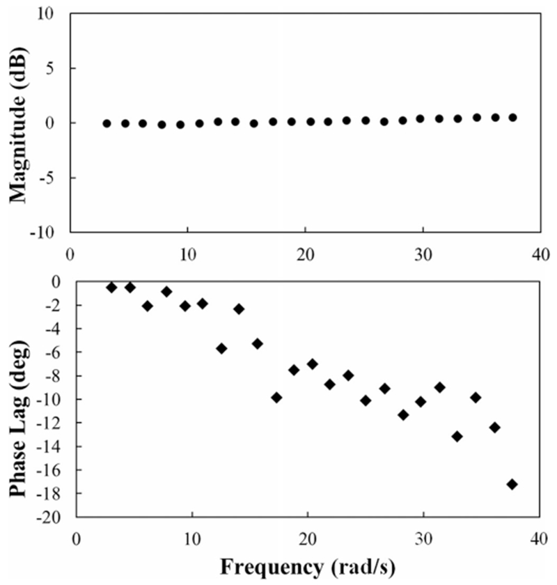
Example Bode plot of CAFE response to increased frequency oscillations at the MCP joint with a weighted, articulated artificial finger.
The desired and measured (camera system) trajectories for MCP, PIP, and DIP in the tracking of three simultaneously applied sinusoids were then compared (see Fig. 9). Sample correlation coefficients between observed and desired angular positions were greater than 0.99 for all joints (see Table 3). Temporal lag was less than 0.3 s and average overshoot was less than 1.1° for each joint during the simultaneous movement.
Fig. 9.

Camera observed MCP (blue), PIP (red), and DIP (green) joint angles versus target (black) joint angles during simultaneous tracking of sinusoids with different frequencies at each joint, π/4 (MCP), π/2 (PIP), and π (DIP). All correlation coefficients are greater than 0.99.
TABLE III.
Simultaneous Sinusoid Performance
| Joint | MCP | PIP | DIP |
|---|---|---|---|
| Phase Lag (s) | 0.029 | 0.013 | 0.013 |
| Overshoot (°) | −0.251 | −0.262 | −1.094 |
Average phase lag and overshoot for each joint during a 6-s simultaneous sinusoidal movement of all three joints.
B. Kinetic Control
The calibration curve of the strain gauge force sensor was highly linear (R2 > 0.999). Importantly, hysteresis was minimal. Force readings were largely invariant to position along the beam.
We conducted step torque experiments to evaluate the torque control of the system. The torque controller was left slightly underdamped to improve rise time. The output torque reached the target torque of 0.57 N∙m (corresponding to a 20-N flexion force on the finger) in less than 60 ms for a single trial (see Fig. 10). The RMS error of the contact beams at steady state is 5.3 × 10⁻³ N∙m (0.93% of the target torque) with an average error of 6.0 × 10⁻³ N∙m (0.1%) for the same trial. Contact beam differed from the load cell measurement by a RMS steady-state error of 2.3%.
Fig. 10.
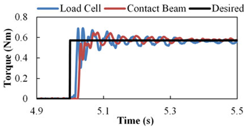
Example 0.57 N∙m step torque at the MCP joint with desired torque (black), external load cell (blue), and contact rod (red) measurements.
To test the torque capacity, the motor command voltage was increased until the output torque exceeded the design torque of 2.0 N∙m at the MCP joint (see Fig. 11). This isometric output was achieved at stall around a motor excitation of 2 V, 20% of the maximum possible excitation. Taken together, these results demonstrated the capability of the CAFE to promptly provide the required joint torque.
Fig. 11.
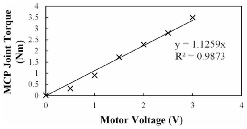
Flexion torque at the MCP in response to steps in motor voltage. The torque output surpasses the design requirement (2 N∙m) at less than 2 V.
VI. Discussion
While adding only 138 g of mass to the finger, considerably less than comparable systems [19]—[25], the CAFE is capable of moving at substantial speeds and providing the considerable joint torque. The mass on the CAFE may be reduced even further with the implementation of carbon or 3-D printed metal–ceramic composites. Active control input can be provided to additionally lessen device effects on voluntary movement. As such, the CAFE can achieve minimal interference (zero impedance).
The CAFE does not account for potentially variable CoR of the joints and one can imagine the device may slip as a result. While these errors will be explored in the future, it is possible that passive DoF could be incorporated in the mechanical design to account for CoR variability as has been implemented in similar devices [21], [33]. Alternatively, a remote CoR [31]–[33], [42] would rely on the user’s actual joints, but would also require the user’s digit to carry inflated and off-axis forces and torques, jeopardizing natural movement.
The extent to which compliance will affect deviation between the user and the device will be minimal. For a significant translational or rotational mismatch to occur between the user and the device, multiple segments of the finger must move relative to the device. This is not feasible, as the device has multiple points of contact with the user and is well grounded to the bony structures of the wrist.
High backdrivability is made possible by the dual cable actuation system. The cable transmission, with gearing located directly at the joints, permits the actuators to be placed proximal to the hand while minimizing the frictional losses that are inherent to other transmissions, such as Bowden cables. This implementation also serves to reduce the effect of motor inertia reflected on the joints as the motors act in opposition on the shared pulley. The tension forces of each motor counter one another, offsetting the effect on the user. A tradeoff is made in terms of control complexity for active movements and additional hardware with this design.
Namely, two motors are needed to control each joint, as each cable is only capable of pulling. These motor pairs must act in concert to incite movement while maintaining tension in all cables. Additionally, the cables to more distal joints must respond to movement of more proximal joints; cable length is a function of all preceding joint angles as well as the joint the cable controls.
The CAFE allows for a wide finger workspace, low interference, and arm mobility [36]. The capabilities of the device exceed those of other current exoskeletons in power, control and feedback resolution, and minimal impedance to movement. For example, similar devices for the hand utilize Bowden cables for each joint [21] or for the finger as a whole [18]. While these devices have no presence on the forearm, the use of Bowden cables significantly limits its bandwidth as the result of stiction and the resolution of control is as much as 100 times less than that of the CAFE [21]. Another promising device, which extends across 18 DoF of the hand [19], has a smaller bandwidth and considerably less MCP torque. Other devices [14], [20], [32], [42] have their advantages and specific applications for which they excel, but many devices lack performance validation and the CAFE consistently outperforms across the range of criteria presented in this paper when data are available for comparison.
Performance testing via frequency response was conducted up to 12π (6 Hz); exceeding frequencies attainable in the human index finger [40]. This frequency, at amplitude of 30°, achieves good performance in excess of design requirements with minimal amplitude mismatch and only 17° of phase lag at the highest examined frequency. The device was not, however, tested until it reached the signature drop off to 3 dB that we would expect to determine the bandwidth of the system. We anticipate that significant further increases in frequency will lead to this drop in achieved angle during oscillation as well as a continued increase in phase lag. The MCP joint was selected for inclusion in this paper given the greater mass and inertia it experiences as compared to the other joints. It is expected that the PIP and DIP joints will follow the same pattern of performance, although gains are subject to independent tuning.
To further improve performance, we are developing an adaptive controller which estimates inertia H, interaction C, gravitational G, tension-induced τT, and contact-induced τC parameters based on the adaptive control law [Yâ (3)]. Taking into account this model has the potential to greatly improve position and force controllability across the range of operating frequencies, in response to step input, and between users
| (3) |
VII. Conclusion
CAFE sensory feedback was accurate and reliable. Joint angles derived from the encoders were in close agreement with those obtained from an external camera system (R2 = 0.999). This suggests that inconsistencies in cable winding around the pulleys and motor spools have minimal effect on joint angle. The torque measurements obtained with strain gages on the contact beams closely match with the commercial load cell (2.3% RMS steady-state error).
Kinematic testing confirmed the ability of the CAFE to track desired angle trajectories over time. Tracking of the desired ramps was quite good, with R2 values of 0.99 or greater. Tracking of the independent sinusoids simultaneously with each digit was also successful as evidenced by correlation factors exceeding 0.99. Precise control could be maintained with minimal performance loss across and beyond the range of operating frequencies. The gain remained within 0.5 dB and the phase lag within 20° up to 6 Hz for a sinusoid with 30° amplitude.
Examination of kinetic control confirmed the ability of the CAFE to precisely provide a desired isometric torque to finger joints. Even with a rapid rise time under 60 ms, RMS steady-state error was only 0.93% with an average error of 0.1%. The exoskeleton also proved to be quite strong. Almost 3.5 N∙m of torque (well exceeding the 2.0 N∙m requirement) could be achieved at the MCP joint without damage to the exoskeleton.
Collectively, the CAFE performance and flexibility is valuable for evaluating the efficacy of rehabilitation strategies and pursuing the study of motor control. For example, the high achievable speeds will permit assessment of spasticity [43] and isokinetic strength and power. The large torque capabilities will permit evaluation of peak strength. High backdrivability with the capacity for large perturbation forces permits implementation of force fields, such as attractive, repulsive, haptic or viscous curl fields [44]–[48] for motor learning paradigms. The CAFE is, however, limited to the flexion/extension DoF of the index finger, with the initial abduction/adduction DoF fixed. Future improvements may include actuation of this axis of rotation or measurement of index Anger torque in the abduction/ adduction direction.
Future advancement of the control system will include a high-level supervisory controller to provide different training tasks. Additional training strategies, e.g., assist-as-needed, resist-as-needed, and error augmentation, will be integrated in this high-level supervisory control to enhance the functionality of the CAFE. Control strategies, including the previously mentioned adaptive controller, will be investigated to further exploit the capabilities of the device, maintain performance when in contact with a human user and, ultimately, execute intervention strategies. Performance of the CAFE with human subjects will be examined next.
Acknowledgment
The authors acknowledge the contributions of T. Worsnopp to the initial design of the CAFE, and E. Colgate and M. Peshkin from the Laboratory for Intelligent Mechanical Systems at Northwestern University for their insight and support of this project.
This work was partially supported in part by the National Institutes of Health under Grant R24HD050821 and Grant 5R21HD055478-02.
Biographies

Christopher L. Jones (S’09) received the B.S. degree in aerospace engineering from the Illinois Institute of Technology, Chicago, in 2007, where he is currently working toward the Ph.D. degree in biomedical engineering.
His research interests include robotics, mechatronics, dynamics, controls, human–robot interaction, rehabilitation, learning, and motor control.

Furui Wang received the B.S. and M.S. degrees in mechanical engineering from the University of Science and Technology of China, Hafei, China, in 2003 and 2006, respectively, and the Ph.D. degree in mechanical engineering from Vanderbilt University, Nashville, Tennessee, in 2011.
He is currently with Abbott Laboratories, Princeton, NJ. His research interests include rehabilitation robotics, hybrid system control, and system dynamics.

Robert Morrison (S’10) is currently working toward the B.S. degree in biomedical engineering and electrical engineering at the Illinois Institute of Technology, Chicago.
He is currently with the Rehabilitation Institute of Chicago, Chicago, IL. His research interests include neurophysiology, neural engineering, neural control of movement, and brain–computer interfaces.

Nilanjan Sarkar (S’92–M’93–SM’04) received the Ph.D. degree in mechanical engineering and applied mechanics from the University of Pennsylvania, Philadelphia, in 1993.
He is currently a Professor of Mechanical Engineering and Computer Engineering at Vanderbilt University, Nashville, Tennessee. His current research interests include human–robot interaction, rehabilitation robotics, affective computing, dynamics, and control.

Derek G. Kamper (M’97) received the B.E. degree in electrical engineering from Dartmouth College, Hanover, NH, in 1989, and the M.S. and Ph.D. degrees in biomedical engineering from The Ohio State University, Columbus, in 1992 and 1997, respectively.
He is currently an Associate Professor in the Department of Biomedical Engineering, Illinois Institute of Technology, Chicago, and a Research Scientist at the Rehabilitation Institute of Chicago, Chicago. His research interests include neurorehabilitation, mechatronics, and upper extremity neuromechanics.
Footnotes
Color versions of one or more of the figures in this paper are available online at http://ieeexplore.ieee.org.
Contributor Information
Christopher L. Jones, Department of Biomedical Engineering, Illinois Institute of Technology, Chicago, IL 60616 USA (jonechr@hawk.iit.edu).
Furui Wang, Abbott Laboratories, Princeton, NJ 08540 USA (furui.wang@gmail.com).
Robert Morrison, Rehabilitation Institute of Chicago, Chicago, IL 60611 USA (rmorris4@hawk.iit.edu).
Nilanjan Sarkar, Department of Mechanical Engineering, Vanderbilt University, Nashville, TN 37212 USA (nilanjan.arkar@Vanderbilt.edu)..
Derek G. Kamper, Department of Biomedical Engineering, Illinois Institute of Technology, Chicago, IL 60616 USA; Rehabilitation Institute of Chicago, Chicago, IL 60611 USA (d-kamper@northwestern.edu).
References
- [1].Cruz EG, Waldinger HC, and Kamper DG, “Kinetic and kinematic workspaces of the index finger following stroke,” Brain, vol. 128,pp. 1112–1121, May 2005. [DOI] [PubMed] [Google Scholar]
- [2].Seo NJ, Rymer WZ, and Kamper DG, “Altered digit force direction during pinch grip following stroke,” Exp. Brain Res, vol. 202, pp. 891–901, May 2010. [DOI] [PubMed] [Google Scholar]
- [3].Seale GS, Berges IM, Ottenbacher KJ, and Ostir GV, “Changein positive emotion and recovery of functional status following stroke,” Rehabil. Psychol, vol. 55, pp. 33–39, Feb. 2010. [DOI] [PMC free article] [PubMed] [Google Scholar]
- [4].Center for Disease Control, “Outpatient rehabilitation among stroke survivors: 21 States and the District of Columbia,” Morb. Mortal Wkly. Rep, vol. 56, pp. 504–507, 2007. [PubMed] [Google Scholar]
- [5].Lloyd-Jones D, Adams RJ, Brown TM, Carnethon SDM, De Simone G, Ferguson TB, Ford E, Furie K, Gillespie C, Go A, Greenlund K, Haase N, Hailpern S, Ho PM, Howard V, Kissela B, Kittner S,Lackland D, Lisabeth L,Marelli A, McDermott MM, Meigs J,Mozaffarian D, Mussolino M, Nichol G, Roger VL, Rosamond W,Sacco R, Sorlie P, Roger VL, Thom T, Wasserthiel-Smoller S, Wong ND, and Wylie-Rosett J, “Heart disease and stroke statistics–2010 update: A report from the American Heart Association,” Circulation, vol. 121, pp. e46–e215, Feb. 23, 2010. [DOI] [PubMed] [Google Scholar]
- [6].American Heart Association, “Heart disease and stroke statistics 2010 update,” Circulation, vol. 121, pp. 46–215, 2009. [DOI] [PubMed] [Google Scholar]
- [7].Wolf SL, Blanton S, Baer H, Breshears J, and Butler AJ, “Repetitive task practice: A critical review of constraint-induced movement therapy in stroke,” Neurologist, vol. 8, pp. 325–338, Nov. 2002. [DOI] [PMC free article] [PubMed] [Google Scholar]
- [8].Winstein CJ, Rose DK, Tan SM, Lewthwaite R, Chui HC, and Azen SP, “A randomized controlled comparison of upper-extremity rehabilitation strategies in acute stroke: A pilot study of immediate and long-term outcomes,” Arch. Phys. Med. Rehabil, vol. 85, pp. 620–628, Apr. 2004. [DOI] [PubMed] [Google Scholar]
- [9].Page SJ, Sisto S, Levine P, and McGrath RE, “Efficacy of modified constraint-induced movement therapy in chronic stroke: A single-blinded randomized controlled trial,” Arch. Phys. Med. Rehabil, vol. 85, pp. 14–18, Jan. 2004. [DOI] [PubMed] [Google Scholar]
- [10].Liepert J, Miltner WH, Bauder H, Sommer M, Dettmers C, Taub E, and Weiller C, “Motor cortex plasticity during constraint-induced movement therapy in stroke patients,” Neurosci. Lett, vol. 250, pp. 5–8, Jun. 26, 1998. [DOI] [PubMed] [Google Scholar]
- [11].Liepert J, Bauder H, Wolfgang HR, Miltner WH, Taub E, and Weiller C, “Treatment-induced cortical reorganization after stroke in humans,”Stroke, vol. 31, pp. 1210–1216, Jun. 2000. [DOI] [PubMed] [Google Scholar]
- [12].Pignolo L, “Robotics in neuro-rehabilitation,” J. Rehabil. Med, vol. 41, pp. 955–960, Nov. 2009 [DOI] [PubMed] [Google Scholar]
- [13].Adamovich SV, Fluet GG, Mathai A, Qiu Q, Lewis J, and Merians AS, “Design of a complex virtual reality simulation to train finger motion for persons with hemiparesis: A proof of concept study,” J. Neuroeng. Rehabil, vol. 6, p. 28, 2009. [DOI] [PMC free article] [PubMed] [Google Scholar]
- [14].Schabowsky CN, Godfrey SB, Holley RJ, and Lum PS, “Development and pilot testing of HEXORR: Hand EXOskeleton rehabilitation robot,” J. Neuroeng. Rehabil, vol. 7, p. 36, 2010. [DOI] [PMC free article] [PubMed] [Google Scholar]
- [15].Jack D, Boian R, Merians AS, Tremaine M, Burdea GC, Adamovich SV, Recce M, and Poizner H, “Virtual reality-enhanced stroke rehabilitation,” IEEE Trans. Neural Syst. Rehabil. Eng, vol. 9, no. 3, pp. 308–318, Sep. 2001. [DOI] [PubMed] [Google Scholar]
- [16].Takahashi CD, Der-Yeghiaian L, Le V, Motiwala RR, and Cramer SC, “Robot-based hand motor therapy after stroke,” Brain, vol. 131, pp. 425–437, Feb. 2008. [DOI] [PubMed] [Google Scholar]
- [17].Dovat L, Lambercy O, Gassert R, Maeder T, Milner T, Leong TC, and Burdet E, “Handcare: A cable-actuated rehabilitation system to train hand function after stroke,” IEEE Trans. Neural Syst. Rehabil. Eng, vol. 16, no. 6, pp. 582–591, Dec. 2008. [DOI] [PubMed] [Google Scholar]
- [18].Chiri AV, Giovacchini N, Roccella F, Vecchi S, Carrozza F, and Carrozza M, “Mechatronic design and characterization of the index finger module of a hand exoskeleton for post-stroke rehabilitation,” IEEE/ASME Trans. Mechatronics, vol. 17, no. 5, pp. 884–894, Oct. 2012. [Google Scholar]
- [19].Ueki S, Kawasaki H, Ito S, Nishimoto Y, Abe M, Aoki T, Ishigure Y, Ojika T, and Mouri T, “Development of a hand-assist robot with multi-degrees-of-freedom for rehabilitation therapy,” IEEE/ASME Trans. Mechatronics, vol. 17, no. 1, pp. 136–146, Feb. 2012. [Google Scholar]
- [20].Ferre M, Galiana I, Wirz R, and Tuttle N, “Haptic device for capturing and simulating hand manipulation rehabilitation,” IEEE/ASME Trans. Mechatronics, vol. 16, no. 5, pp. 808–815, Oct. 2011. [Google Scholar]
- [21].Wang J, Li J, Zhang Y, and Wang S, “Design of an exoskeleton for index finger rehabilitation,” in Proc. IEEE Eng. Med. Biol. Soc, Sep. 2009, vol. 2009, pp. 5957–5960. [DOI] [PubMed] [Google Scholar]
- [22].Wege A andHommel G, “Development and control of a hand exoskeleton for rehabilitation of hand injuries,” in Proc. IEEE/RSJ Int. Conf. Intell. Robots Syst., Aug. 2005, pp. 3046–3051. [Google Scholar]
- [23].Sarakoglou I, Tsagarakis NG, and Caldwell DG, “Occupational and physical therapy using a hand exoskeleton based exerciser,” in Proc. IEEE/RSJ Int. Conf. Intell. Robots Syst., Sep./Oct. 2004, pp. 2973–2978. [Google Scholar]
- [24].DiCicco M, Lucas L, andMatsuoka Y, “Comparison of control strategies for an EMG controlled orthotic exoskeleton for the hand,” in Proc. IEEE Int. Conf. Rob. Autom., Apr./May 2004, pp. 1622–1627. [Google Scholar]
- [25].Kawasaki H, Ito S, Ishigure Y, Nishimoto Y, Aoki T, Mouri T, Sakaeda H, and Abe M, “Development of a hand motion assist robot for rehabilitation therapy by patient self-motion control,” in Proc. IEEE 10th Int. Conf. Rehabil. Rob., Jun. 2007, pp. 234–240. [Google Scholar]
- [26].Kamper DG and Rymer WZ, “Impairment of voluntary control of finger motion following stroke: Role of inappropriate muscle coactivation,” Muscle Nerve, vol. 24, pp. 673–681, May 2001. [DOI] [PubMed] [Google Scholar]
- [27].Saunders DH, Greig CA, Young A, and Mead GE, “Association of activity limitations and lower-limb explosive extensor power in ambulatory people with stroke,” Arch. Phys. Med. Rehabil, vol. 89, pp. 677–683, Apr. 2008. [DOI] [PubMed] [Google Scholar]
- [28].Gutnik B, Nash D, Ricacho N, Hudson G, and Skirius J, “Power of performance of the thumb adductor muscles: Effect of laterality and gender,” Medicina (Kaunas), vol. 42, pp. 653–660, 2006. [PubMed] [Google Scholar]
- [29].Kamper DG et al. , “Relative contributions of neural mechanisms versus muscle mechanics in promoting finger extension deficits following stroke,” Muscle Nerve, vol. 28, pp. 309–318, Sep. 2003. [DOI] [PubMed] [Google Scholar]
- [30].Kamper DG et al. , “Extrinsic flexor muscles generate concurrent flexion of all three finger joints,” J. Biomech, vol. 35, pp. 1581–1589, Dec. 2002. [DOI] [PubMed] [Google Scholar]
- [31].Baumann R, Maeder W, Glauser D, and Clavel R, “The pantoscope: A spherical remote-center-of-motion parallel manipulator for force reflection,” in Proc. IEEE Int. Conf. Rob. Autom., Apr. 1997, vol. 1, pp. 718–723. [Google Scholar]
- [32].Blake J and Gurocak HB, “Haptic glove with MR brakes for virtual reality,” IEEE/ASME Trans. Mechatronics, vol. 14, no. 5, pp. 606–615, Oct. 2009. [Google Scholar]
- [33].Wang F, Shastri M, Jones C, Kamper D, and Sarkar N, “Design and control of an actuated thumb exoskeleton for hand rehabilitation following stroke,” in Proc. IEEE Int. Conf. Rob. Autom., Shanghai, China, May 2011, pp. 3688–3693. [Google Scholar]
- [34].Zhang X, Lee SW, and Braido P, “Determining finger segmental centers of rotation in flexion-extension based on surface marker measurement,” J. Biomech, vol. 36, pp. 1097–1102, Aug. 2003. [DOI] [PubMed] [Google Scholar]
- [35].Chang LY and Pollard NS, “Constrained least-squares optimization for robust estimation of center of rotation,” J. Biomech, vol. 40, pp. 1392–1400, 2007. [DOI] [PubMed] [Google Scholar]
- [36].Iwamuro BT, Cruz EG, Connelly LL, Fischer HC, and Kamper DG, “Effect of a gravity-compensating orthosis on reaching after stroke: Evaluation of the therapy assistant WREX,” Arch. Phys. Med. Rehabil, vol. 89, pp. 2121–2128, Nov. 2008. [DOI] [PubMed] [Google Scholar]
- [37].Townsend WT and Salisbury JK, “Mechanical bandwidth as a guideline to high-performance manipulator design,” in Proc. IEEE Int. Conf. Rob. Autom., May 1989, pp. 1390–1395. [Google Scholar]
- [38].T. R. Omega WEB. (Jul. 2011). [Online]. Available: http://www.omega.com/faq/pressure/pdf/positioning.pdf
- [39].xPC Target documents. [Online]. Available: http://www.mathworks.com/access/helpdesk/help/toolbox/xpc/
- [40].Aoki T, Francis PR, and Kinoshita H, “Differences in the abilities of individual fingers during the performance of fast, repetitive tapping movements,” Exp. Brain Res, vol. 152, pp. 270–280, Sep. 2003. [DOI] [PubMed] [Google Scholar]
- [41].Deshpande AD, Xu Z, Weghe MJV, Brown BH, Ko J, Chang LY, Wilkinson DD, Bidic SM, and Matsuoka Y, “Mechanisms of the anatomically correct testbed hand,” IEEE/ASME Trans. Mechatronics, vol. 18, no. 1, pp. 1–13, February 2013. [Google Scholar]
- [42].Wang S, Li J, and Zheng R, “A resistance compensation control algorithm for a cabledriven hand exoskeleton for motor function rehabilitation,” Intell. Rob. Appl, vol. 6425, pp. 398–404, 2010. [Google Scholar]
- [43].Kamper DG and Rymer WZ, “Quantitative features of the stretch response of extrinsic finger muscles in hemiparetic stroke,” Muscle Nerve, vol. 23, pp. 954–961, Jun. 2000. [DOI] [PubMed] [Google Scholar]
- [44].Scheidt RA, Reinkensmeyer DJ, Conditt MA, Rymer WZ, and Mussa-Ivaldi FA, “Persistence of motor adaptation during constrained, multi-joint, arm movements,” J. Neurophysiol, vol. 84, pp. 853–862, Aug. 2000. [DOI] [PubMed] [Google Scholar]
- [45].Patton JL, Stoykov ME, Kovic M, and Mussa-Ivaldi FA, “Evaluation of robotic training forces that either enhance or reduce error in chronic hemiparetic stroke survivors,” Exp. Brain Res, vol. 168, pp. 368–383, Jan. 2006. [DOI] [PubMed] [Google Scholar]
- [46].Vergaro E, Casadio M, Squeri V, Giannoni P, Morasso P, and Sanguineti V, “Self-adaptive robot training of stroke survivors for continuous tracking movements,” J. Neuroeng. Rehabil, vol. 7, p. 13, 2010. [DOI] [PMC free article] [PubMed] [Google Scholar]
- [47].Casadio M, Giannoni P, Morasso P, Sanguineti V, Squeri V, and Vergaro E, “Training stroke patients with continuous tracking movements: Evaluating the improvement of voluntary control,” in Proc. IEEE Eng. Med. Biol. Soc. Conf., Sep. 2009, pp. 5961–5964. [DOI] [PubMed] [Google Scholar]
- [48].Squeri V, Casadio M, Vergaro E, Giannoni P, Morasso P, and Sanguineti V, “Bilateral robot therapy based on haptics and reinforcement learning: Feasibility study of a new concept for treatment of patients after stroke,” J. Rehabil. Med, vol. 41, pp. 961–965, Nov. 2009 [DOI] [PubMed] [Google Scholar]


