Abstract
This paper describes how to take advantage of the replacement of an intensity camera with a polarization camera in a standard differential interference contrast (DIC) microscope. Using a polarization camera enables snapshot quantitative phase analysis so that real-time imaging of living transparent tissues become possible. Using our method, we quantify the phase measurement accuracy using a phantom consisting of glass beads embedded in lacquer. In order to demonstrate these advantages, we image the pumping heart and blood flow in a living medaka egg.
1. Introduction
Differential interference contrast (DIC) microscopy [1] is a widely used method for observing tissues or cells in vivo without the need for applying florescent dyes. DIC microscopy allows analysis of detailed structures, high sensitivity in detecting phase information, and has a strong capability for optical sectioning [2]. Many researchers have proposed methods for the quantitative phase measurement of volumes using transmission DIC microscopy [3,4], and surface profile measurement using reflection DIC microscopy [5–7]. Ishiwata et al. proposed a retardation-modulated DIC (RM-DIC) microscope for quantitative measurement of planar microstructure at a given focal depth [8,9], and to measure 3D phase volume by optical sectioning [2]. However, these quantitative reconstruction methods [2–9] can require significant computation for each phase image because of the need to acquire multiple images for use with the phase shift technique.
We show below that it is possible to obtain a quantitative phase image from a single raw frame, so that real-time video is possible for a DIC microscope using a polarization camera – a camera for which a micropolarizer array has been attached to a detector array [10–12]. While Fabre et al. have previously shown how to make use of a photonic crystal polarization camera [11] with a DIC microscope, they used scanning to collect multiple raw images in order to obtain a single phase image [13]. Thus, they were unable to demonstrate video imaging of dynamic phase objects. We demonstrate that it is possible to capture measurements at the native frame rate of the polarization camera, and that through deconvolution with the DIC system’s inverse MTF, we can convert the raw intensity data into quantitative phase images.
In Section 2 below, we introduce how to calculate a quantitative phase image from one image captured by a polarization camera. In Section 3, we evaluate the proposed method for getting accurate phase measurement using a sample of glass beads inside a lacquer medium. In order to demonstrate the advantages of our method, we also show a video-rate phase measurement of rapid motion in a living medaka egg.
2. Snapshot phase analysis method
We start with a simple one-dimensional model consisting of a pure phase object imaged by the DIC microscope, generating an intensity distribution I(x) at the detector plane. The microscope consists of a light source, illumination optics, the phase object, imaging optics, and a detector array (Fig. 1).
Fig. 1.
Simple model of a transmission microscope.
According to Hopkins’ theory [14] and the partial coherence theory of a microscope [15], the image intensity distribution I(x) on the detector array can be defined as
| (1) |
where O(fx) is the Fourier transform of phase object o(x), and R(fx, f'x) is the complex-valued transmission cross-coefficient (TCC) given by
| (2) |
for Q(ξ) the intensity distribution of the illuminating system, and p(ξ) the complex-valued pupil function.
The DIC microscope utilizes lateral shearing interference between two orthogonally polarized beams produced by two Nomarski prisms, in which the beams pass through slightly different areas (shear distance Δ) of a specimen. The two beams are then brought back together by a second pair of Nomarski prisms that cancel the shear. The resulting interferogram observed at the image plane encodes the spatial gradient of the object phase along the shear direction.
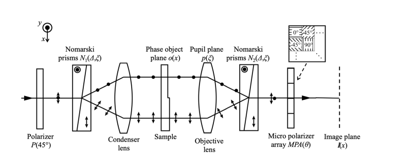
Figure 2 shows our proposed optical layout for the DIC microscope using a polarization camera. The DIC microscope is set to generate π/2 of retardation along the shear axis between the two Nomarski prisms because the microstructure phase is emphasized best at this setting. The polarization camera can detect four kinds of intensities with each polarizer azimuthal angle (0°, 45°, 90°, and −45°) by one image. The intensities detected using the pixels oriented at 0° and 90° of the micropolarizer array do not produce interference because these axes are aligned to the shearing direction. Therefore we use only the two intensities detected using the pixels oriented at 45° and −45° and ignore the 0° and 90° data.
Fig. 2.
The optical setup of the DIC microscope using a polarization camera.
The polarization elements are defined with the following Jones matrices:
| (3) |
where, P(45°) and MPA(θ) are Jones matrices of the polarizer and the micro polarizer array oriented at θ = 0°, 45°, 90°, and −45°, and N(Δ, ξ) is Jones matrix of the Nomarski prism.
The TCC R(fx,f'x) in the case of a polarization camera is rewritten using Eqs. (2) and (3) as
| (4) |
where
| (5) |
According to Ishiwata’s theory [8,9], we will assume that the object phase can be approximated as a small phase distribution atop a (potentially large) spatially-constant phase. Therefore, phase object o(x) can be approximated by its Taylor expansion about the constant phase value as
| (6) |
for transmission C and spatially-constant phase φ0. The Fourier transform of phase object o(x) can be expressed as
| (7) |
where δ(fx) is the Dirac delta function, and Φ(fx) is the Fourier transform of phase distribution φ(x). Here is the convolution operator. Assuming that the pupil is independent of any polarization, the intensity distribution I(x,θ) is rewritten by substituting Eqs. (4) and (7) to Eq. (1). Since the introduction of the polarization calculus has converted R(fx,f'x) from a scalar to a vector, we also need to convert the complex conjugate in Eq. (1) to an adjoint operator (i.e. conjugate transpose), producing
| (8) |
where
| (9) |
Here M(0), M(fx), m0(fx), and md(fx) describe the illumination profiles in terms of the two sheared beams illuminating the sample. We see that the intensity distribution I(x,θ) has five terms comprising three components (a), (b), and (c). The background component (a) consists of M(0) plus an integral that evaluates to a constant – together these represent the DC part of the illumination and object transmission – plus an integral that expresses the illumination profile due to the pair of illumination beams sheared by separation Δ. The second component (b) is the primary item of interest – the object phase gradient given by taking the difference between the two shifted versions of the object phase. The difference operation is due to the Fourier transform of the sine function being a pair of Dirac delta functions of opposite sign. Finally, the third component (c) is the transmitted intensity profile dependent on the squared object phase.
If we approximate the object as having a weak phase variation, the convolved phase, the absolute value and the squared object phase all become approximately zero. As a result, the intensity images (Eq. (8)) captured by the polarization camera depend only on the DC part of background M(0) and the object phase gradient component (b). Thus, in the weak phase variation approximation Eq. (8) becomes:
| (10) |
The object phase gradient (the differential phase distribution) can be obtained by
| (11) |
where
| (12) |
represents the Modulation Transfer Function (MTF) of the DIC microscope.
The phase distribution φ(x) of the observed object can be obtained using the MTF(fx) of the DIC microscope with
| (13) |
where is the Fourier transform function and is the inverse Fourier transform function.
By using the polarization camera, the image phase distribution is measured using two different pixel positions on the polarization camera by Eq. (13). The spatial resolution of the measured phase is increased (worsened) by a factor of 2 in each of the two spatial directions. Therefore, the polarization camera can experience aliasing error due to insufficient spatial sampling. To overcome this problem, Tyo et al. proposed a Fourier-domain pixel interpolation method [16]. This method can reconstruct a spatially band-limited polarization image without instantaneous field of view (IFOV) error by filtering in the frequency domain. We apply this method to the raw captured image in order to extract, I(x, 45°) and I(x, −45°) prior to applying them in Eq. (13). In order to simplify the description of Tyo’s method, we switch from the Jones to the Stokes-Mueller calculus, and expand from one-dimension (x) to two-dimensions (x, y) while maintaining the same image model. At the DIC microscope image plane the Stokes parameters are given by
| (14) |
| (15) |
| (16) |
where I(x, y, θ) is the image captured by the polarization camera for a pixel whose micropolarizer is oriented at angle θ. While we do not make use of the 0° and 90° pixel orientations in the phase imaging analysis, we keep them in the discussion here in order to keep the explanation of the filtering method as clear as possible.
In the frequency domain, (ζ, η) are Fourier spatial frequency axes corresponding to (x, y). We write the Fourier transforms of Stokes parameters s0(x, y), s1(x, y), and s2(x, y) as S0(ζ, η), S1(ζ, η), and S2(ζ, η). Using the discrete-space Fourier transform (DSFT) of the image I(x, y, θ), we can separately filter the intensity component S0(ζ, η), the {S1(ζ, η) + S2(ζ, η)} component, and the {S1(ζ, η)−S2(ζ, η)} component such as in Fig. 3. The interpolated images of s0(x, y), s1(x, y) and s2(x, y) can be reconstructed by 4 arithmetic operations and an inverse DSFT after using a low-pass or high-pass filter.
Fig. 3.
The flowchart for the Fourier-domain pixel interpolation method of the polarization camera image.
After the pixel interpolation calibration, Eq. (13) becomes
| (17) |
This Fourier-domain implementation for interpolating the polarization camera’s pixels provides the ideal filtering method from the standpoint of sampling theory. As a result, polarization error caused by edges of object features (i.e. instantaneous field of view errors) and aliasing errors are minimized.
3. Evaluation of quantitative analysis
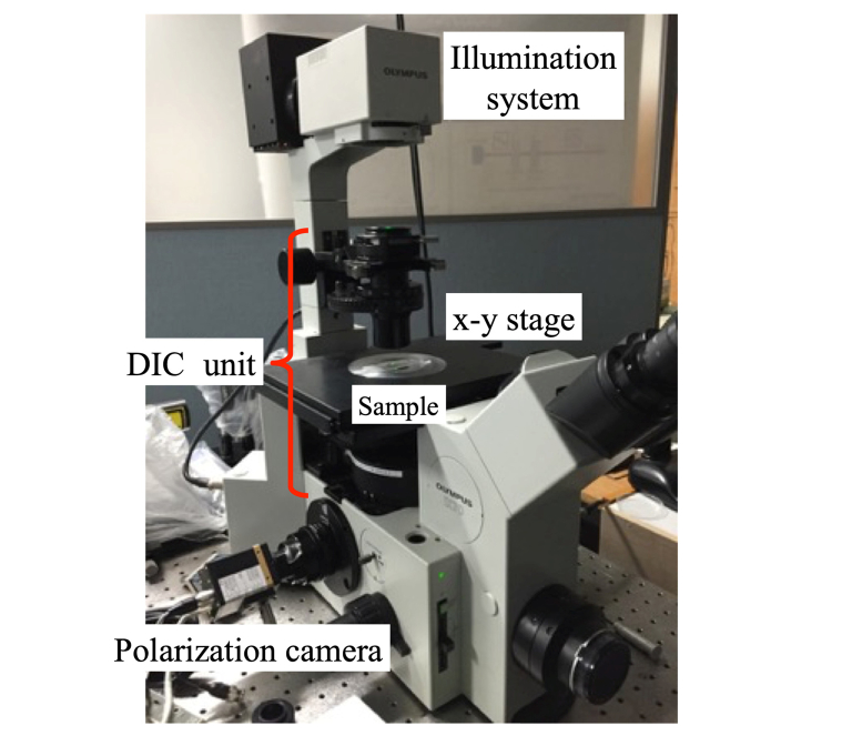
A DIC microscope (Olympus IX70) using a 4D Technology PolarCam (V model) polarization camera is shown in Fig. 4. The light from a halogen lamp is transmitted through a 650 ± 25 nm bandpass filter into the DIC unit. The polarization camera exhibits pixel extinction ratios of ~30 across the visible spectral range, the pixel size is 7.5 × 7.5 μm, the overall number of pixels is 648 × 460, and the maximum camera frame rate is 135 Hz.
Fig. 4.
The DIC microscope using a polarization camera.
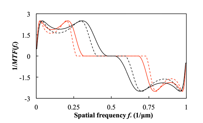
In our analysis, we use MTF(fx) calculated by Eq. (12) using the illumination aperture, wavelength, shear distance Δ, NA and magnification of the objective lens, then we calculate 1/MTF(fx) using a Wiener filter. Figure 5 shows the inverse MTF for our system, showing that the system suppresses low and medium spatial frequencies (fx < 0.4μm−1 and fx > 0.6μm−1, for the 20 × lens) while maintaining the spatial frequencies near 0.5 μm−1.
Fig. 5.
The reciprocal MTF(fx) of our DIC microscope. The red curves are for our 30 × objective lens (NA = 0.40), while the black curves are for our 20 × objective lens (NA = 0.40). The solid curve is the MTF at maximum aperture, while the dashed curve is the MTF at half aperture.
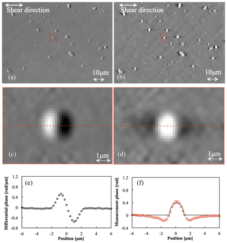
In order to test our approach quantitatively, we measure the phase profile of glass beads (refractive index n1 = 1.56) embedded in a lacquer medium (refractive index n2 = 1.54) to determine how well the system can estimate quantitative phase using the proposed analysis. The diameter d of the glass beads is 2 μm. Figure 6 shows the measurement results of the differential phase on a region of our sample before the inverse Fourier transform (calculated by Eq. (11), shown on the left side of the figure) and the quantitative phase after inverse Fourier transform (calculated by Eq. (14), shown on the right side of the figure). The image shown in the figure is sampled at 0.25 μm / pixel
Fig. 6.
The measurement results of the glass beads (n1 = 1.56) embedded in lacquer (n2 = 1.54). We use an NA = 0.4 objective lens, (a), (c) and (e) are the differential phase results, while (b), (d), and (f) are the quantitative phase results. (c) and (d) are the enlarged images of red square of (a) and (b), respectively. (e) and (f) are cross-sections taken at the center of the glass beads (red dished lines of (c) and (d)). The black line of (f) is the calculated theoretical value.
We can see the well-known halo artifact indicated by negative phase values on both sides of the glass beads. The theoretical curve is calculated from the difference of refractive index (n1 − n2 = 0.02), the bead diameter (d = 2 μm), and the wavelength (650 nm).
The halo artifact visible in Fig. 6(f) is caused by insufficient spatial coherence of the illumination system. Nguyen et al. have shown that they were able to successfully remove the artifact by using an external interferometric unit [17], but our system currently does not have a similar hardware setup allowing for removal of the halo. We obtain an absolute maximum phase difference of 0.05 rad between our measurement curve and theoretical curve at the glass bead area without the halo artifact.
4. Video-rate quantitative analysis result
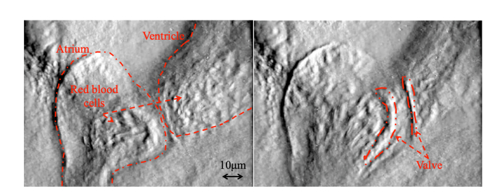
In biology, zebrafish and medaka are often used for investigating the tissue formation process and for the observation of abnormal and healthy cells. Therefore, in order to demonstrate video-rate quantitative phase measurement, we measure a living medaka egg (5~6 days after spawning) (see Fig. 7). Figure 8 shows a 20 Hz video measurement of a medaka heart’s pumping and blood flow [18]. In this measurement, the spatial sampling is 0.25 μm/pixel. The conventional method of quantitative phase measurement (not video-rate measurement) cannot take detailed phase images because of the fast motion, while our method (video-rate measurement) using the polarization camera can obtain clear phase images of the working valve between the atrium and the ventricle, and movement of red blood cells even during the heart’s pumping action.
Fig. 7.
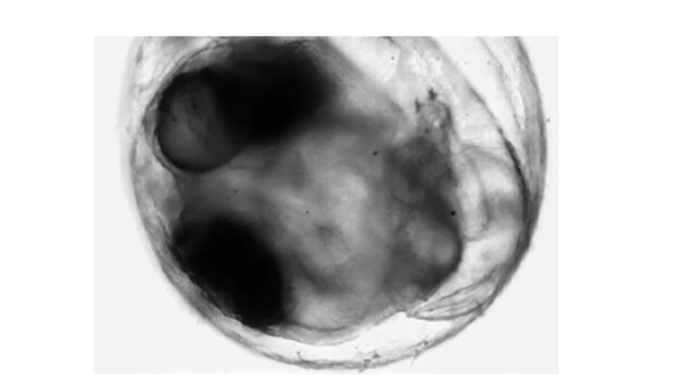
A living medaka egg as sample for video-rate measurement.
Fig. 8.
Two frames from a quantitative phase video of the pumping of a medaka heart, captured at a 20 Hz frame rate [18]. (Visualization 1 (9.1MB, mp4) ).
5. Conclusion
Adding a polarization camera to a DIC microscope allows video-rate quantitative phase measurement of transparent samples. We can extract the differential phase component from the DIC images captured by the polarization camera, and reconstruct the quantitative phase distribution from the differential phase by our proposed analysis. Our method can measure the depth-integrated phase to an accuracy of better than 0.05 rad. Conventional quantitative phase microscopy without using a polarization camera cannot measure dynamic phase objects or object that move quickly during measurement. Our method, however, can achieve accurate measurement of these dynamic objects despite their movement. As a result, we can observe the structures of the living tissue without staining.
Acknowledgements
We would like to thank Prof. Toyohiko Yatagai, Dr. Wataru Ishiwata and Olympus Corporation for useful discussions, for providing the DIC microscope, and for the DIC MTF information for this work. This work was supported by the MEXT Opto-Bio Project.
Funding
MEXT.
Disclosures
The authors declare that there are no conflicts of interest related to this article.
References
- 1.Nomarski G., “Differential microinterferometer with polarized waves,” J. Phys. Radium 16, 9S (1955). [Google Scholar]
- 2.Noguchi A., Ishiwata H., Itoh M., Yatagai T., “Optical sectioning in differential interference contrast microscopy,” Opt. Commun. 282(16), 3223–3230 (2009). 10.1016/j.optcom.2009.05.018 [DOI] [Google Scholar]
- 3.Arnison M. R., Larkin K. G., Sheppard C. J. R., Smith N. I., Cogswell C. J., “Linear phase imaging using differential interference contrast microscopy,” J. Microsc. 214(1), 7–12 (2004). 10.1111/j.0022-2720.2004.01293.x [DOI] [PubMed] [Google Scholar]
- 4.King S. V., Libertun A., Piestun R., Cogswell C. J., Preza C., “Quantitative phase microscopy through differential interference imaging,” J. Biomed. Opt. 13(2), 024020 (2008). 10.1117/1.2907328 [DOI] [PubMed] [Google Scholar]
- 5.Lessor D. L., Hartman J. S., Gordon R. L., “Quantitative surface topography determination by Nomarski reflection microscopy. I. Theory,” JOSA 69(2), 357–366 (1979). 10.1364/JOSA.69.000357 [DOI] [PubMed] [Google Scholar]
- 6.Hartman J. S., Gordon R. L., Lessor D. L., “Quantitative surface topography determination by Nomarski reflection microscopy. 2: Microscope modification, calibration, and planar sample experiments,” Appl. Opt. 19(17), 2998–3009 (1980). 10.1364/AO.19.002998 [DOI] [PubMed] [Google Scholar]
- 7.Hartman J. S., Gordon R. L., Lessor D. L., “Nomarski differential interference contrast microscopy for surface slope measurements: an examination of techniques,” Appl. Opt. 20(15), 2665–2669 (1981). 10.1364/AO.20.002665 [DOI] [PubMed] [Google Scholar]
- 8.Ishiwata H., Itoh M., Yatagai T., “Retardation modulated differential interference microscope and its application to 3-D shape measurement,” Proc. SPIE 2873, 21–24 (1996). 10.1117/12.246219 [DOI] [Google Scholar]
- 9.Ishiwata H., Itoh M., Yatagai T., “A new method of three-dimensional measurement by differential interference contrast microscope,” Opt. Commun. 260(1), 117–126 (2006). 10.1016/j.optcom.2005.10.079 [DOI] [Google Scholar]
- 10.Gruev V., Perkins R., York T., “CCD polarization imaging sensor with aluminum nanowire optical filters,” Opt. Express 18(18), 19087–19094 (2010). 10.1364/OE.18.019087 [DOI] [PubMed] [Google Scholar]
- 11.Kawakami S., Kawashima T., Inoue Y., Homma Y., Sato T., Ota S., Nagashima S., Aoki T., “Polarization imaging device utilizing photonic crystal polarizer,” The Transactions of the Institute of Electronics Information and Communication Engineers. C, J90–C17–24, (2007) (Japanese). [Google Scholar]
- 12.Maruyama Y., Terada T., Yamazaki T., Uesaka Y., Nakamura M., Matoba Y., Komori K., Ohba Y., Arakawa S., Hirasawa Y., Kondo Y., Murayama J., Akiyama K., Oike Y., Sato S., Ezaki T., “3.2-MP back-illuminated polarization image sensor with four-directional air-gap wire grid and 2.5-μm pixels,” IEEE Trans. Electron Dev. 65(6), 2544–2551 (2018). 10.1109/TED.2018.2829190 [DOI] [Google Scholar]
- 13.Fabre L., Inoue Y., Aoki T., Kawakami S., “Differential interference contrast microscope using photonic crystals for phase imaging and three-dimensional shape reconstruction,” Appl. Opt. 48(7), 1347–1357 (2009). 10.1364/AO.48.001347 [DOI] [PubMed] [Google Scholar]
- 14.Hopkins H. H., “On the diffraction theory of optical images,” Proc. R. Soc. Lond. A Math. Phys. Sci. 217, 408–432 (1953). [Google Scholar]
- 15.Sirohi R. S., Bhatnagar G. S., “Effect of partial coherence on the resolution of a microscope,” Opt. Acta (Lond.) 17(11), 839–842 (1970). 10.1080/713818258 [DOI] [Google Scholar]
- 16.Tyo J. S., LaCasse C. F., Ratliff B. M., “Total elimination of sampling errors in polarization imagery obtained with integrated microgrid polarimeters,” Opt. Lett. 34(20), 3187–3189 (2009). 10.1364/OL.34.003187 [DOI] [PubMed] [Google Scholar]
- 17.Nguyen T. H., Kandel M., Shakir H. M., Best-Popescu C., Arikkath J., Do M. N., Popescu G., “Halo-free phase contrast microscopy,” Sci. Rep. 7(1), 44034 (2017). 10.1038/srep44034 [DOI] [PMC free article] [PubMed] [Google Scholar]
- 18.While the camera itself is capable of capturing images at frame rates of up to 100 Hz, the camera interface software available to us for this experiment could only run at frame rates up to 20 Hz.


