

Abstract
We have developed photoacoustic microscopy (PAM) with micron-level spatial resolution in all three dimensions (3D). With multi-angle illumination, PAM images from different view angles can be simultaneously acquired for multi-view deconvolution, without the rotation of imaging targets. Side-by-side comparison of this multi-angle-illumination PAM (MAI-PAM) and conventional PAM, which share the same ultrasonic detector, was performed in phantoms and live mice. The phantom study showed that MAI-PAM achieved a high axial resolution of 3.7 µm, which was 10-fold higher than that of conventional PAM and approached the lateral resolution of 2.7 µm. Furthermore, the in vivo study demonstrated that MAI-PAM was able to image the microvasculature in 3D with isotropic spatial resolution.
Capitalizing on the light absorption of hemoglobin, photoacoustic microscopy (PAM) is capable of comprehensive characterization of the microvasculature in vivo1,2. In conventional PAM, however, the axial resolution is determined by the bandwidth of the ultrasonic detector and is typically 1–2 orders of magnitude worse than the lateral resolution, which is determined by the optical focus. The significant anisotropy in spatial resolution presents a huge obstacle for volumetric imaging. Several approaches have been reported to improve the axial resolution of PAM. Optical detection of ultrasound using micro-ring resonators3 and the surface plasmon resonance effect4 or broadband piezoelectric transducers5 can refine the axial resolution by increasing the bandwidth of ultrasonic detection to beyond 100 MHz. However, significant tissue attenuation of high-frequency ultrasound limits in vivo applications of these methods. Nonlinear PAM is another option. When the local optical fluence is sufficiently high, nonlinear photoacoustic processes occur within the optical focal volume. By applying a high-numerical-aperture objective for optical excitation and detecting only the nonlinear part of photoacoustic signal, high axial resolution can also be achieved6. However, for in vivo applications, it remains a challenge to achieve the required high optical fluence deep inside the tissue. Also, the increased deposition of photon energy raises safety concerns.
Multi-view deconvolution is an emerging approach used in light-sheet microscopy to image the target from multiple view angles for improved spatial resolution and contrast7. Lately, this concept was introduced to the field of PAM8. Multi-view deconvolution of the images acquired by conventional PAM at different view angles has led to much improved axial resolution. Although encouraging, this method requires the rotation of imaging targets and thus is not applicable to most animal studies in vivo, including high-resolution imaging of cortical layer-specific hemodynamics and metabolism.
Here, we propose to achieve the multi-view image acquisition by using multi-angle illumination, which circumvents animal rotation. According to the previous multi-view study in conventional PAM8, a minimal number of two views is sufficient to improve the resolution isotropy to 0.8. However, based on our simulation and experimental test [Fig. 1(a–b)], the dual-view configuration is associated with excessive artefacts induced by the absorption of scattered photons. Such artefacts can be reduced by increasing the number of views (Fig. 1a). Balancing the deconvolution accuracy and system complexity, we choose a configuration of three illumination beams with incident angles of 45°, 90° (i.e., perpendicular to the imaging target) and 135°, respectively. In this design, PAM images from all three views can be acquired simultaneously for the deconvolution-based image reconstruction, without the rotation of imaging target.
Fig. 1.

Image reconstruction principle of MAI-PAM. (a) Numerical simulation and (b) experimental test using carbon fiber phantom show that using only two illumination angles (45° and 135°) results in ghost artefacts, as indicated by the white arrows. (c) Reconstruction with three illumination angles. (d) Simulation analysis of the robustness of the multi-view reconstruction in the presence of different signal-to-noise ratio values. PA: photoacoustic.
First, a numerical simulation is performed to test whether this design can indeed improve PAM’s axial resolution. In the test, 3.6-μm-diameter absorbers are randomly distributed in the x–z plane. Incident beams with a focal diameter of 3 μm and incident angles of 45°, 90° and 135° are launched into the numerical phantom to generate photoacoustic signals. An ultrasonic transducer with a central frequency of 38 MHz and a 6-dB bandwidth of 100% is used. The transducer is coaxially aligned with the 90°-incident beam. The foci of all three optical beams and the ultrasonic transducer are overlapped for maximum sensitivity. An iteration-based algorithm for the multi-view deconvolution has been previously developed for light-sheet microscopy7. According to this algorithm, the equations for triple-view imaging at each iteration are8
| (1) |
| (2) |
| (3) |
| (4) |
where uθ denotes the term associated with the illumination from angle θ, Iθ represents the PAM measurement at angle θ, gθ represents the point spread function (PSF) of PAM with the incident angle of θ, gθ’ represents the flipped PSF at angle θ (i.e., gθ’ (x, y) = gθ (–x, –y)), and is the estimated object function at iteration r. The PSF of each view is determined by convolution of the optical and acoustic PSFs at that view angle.
The multi-view deconvolution algorithm is applied to reconstruct the image of the aforementioned numerical phantom. According to the simulation result (Fig. 1c), the PAM images of individual views, generated by convolution of the phantom and the corresponding PSF, show poor axial resolution and thus cannot distinguish two absorbers close to each other along the z-axis. With the multi-view deconvolution, however, all absorbers can be clearly resolved and the reconstructed image matches the ground truth. This numerical experiment suggests that the multi-angle-illumination PAM (MAI-PAM) is capable of improving the resolution isotropy. Considering practical limitations on the signal-to-noise ratio (SNR), we further examined the dependence of the quality of reconstructed image on the SNR. As shown in Fig. 1(d), the reconstruction is robust when the SNR is above 5, which is well within the capability of PAM9.
With the simulation validation, we have implemented MAI-PAM. As shown in Fig. 2(a), our MAI-PAM employs two 532-nm ns-pulsed lasers (GLPM-20-Y13, IPG Photonics) for excitation. The output of laser1 is coupled into a single-mode optical fiber (SMF2; P1-460B-FC-2, Thorlabs) through a fiber collimator (CFC-11X-A, Thorlabs). In contrast, the output of laser2 first passes through a half-wave plate (HWP; WPH05M-532, Thorlabs) and an electro-optical-modulator (EOM; 350–80, Conoptics). When a high voltage (260 V) is applied to the EOM, the polarization of the beam is rotated to the vertical direction by the EOM and HWP. Thus, the beam is reflected by a polarizing beam splitter (PBS; PBS121, Thorlabs) and coupled into a single-mode fiber (SMF3) through a fiber collimator. When a low voltage (0 V) is applied, the light polarization remains horizontal. Thus, it passes through the PBS and is coupled into a single-mode fiber (SMF1) through a collimator. During image acquisition, laser1 and laser2 are triggered alternately with a 100-μs interval, and the EOM voltage alternates between 0 and 260 V with an interval of 200 μs. With this configuration, the laser pulses are evenly allocated to the three fibers for multi-angle illumination. Note that, since laser2 is responsible for the two side views while laser1 is only responsible for the vertical view, half of the pulses from laser1 are discarded. Triggers for the waveform digitizer (DAQ, ATS9350, AlazarTech) are carefully designed to be synchronized with the laser pulses. Note that the multi-angle illumination can also be implemented by using a single laser and two sets of EOM and PBS.
Fig. 2.

Schematic of MAI-PAM. (a) Excitation sources and trigger scheme. HWP, half-wave plate; PBS, polarizing beam splitter; EOM, electro-optical modulator; SMF1, SMF2 and SMF3, single-mode fibers. (b) Configuration of the imaging head. CL, correction lens.
As shown in Fig. 2(b), in the scan head of MAI-PAM, the output beams from SMF1 and SMF3 are respectively collimated by a doublet (f = 25 mm, AC127-025-A, Thorlabs) and then focused into the imaging target via an identical doublet. A correction lens (LA1207-A, Thorlabs) is inserted into the optical path to compensate for the optical aberration at the air-water interface. The two doublets and the correction lens are mounted inside a tube (SM05L20, Thorlabs), and UV glue (NOA61, Thorlabs) is applied between the correction lens and the tube for water proof. Similarly, the output of SMF2 is collimated by a doublet (f = 19 mm, AC127-019-A, Thorlabs) and then focused into the target through a second doublet (f = 25 mm, AC127-025-A, Thorlabs), a correction lens (LA1207-A, Thorlabs), and an ultrasonic transducer. The focusing doublet, correction lens and transducer are mounted inside a customized tube, and UV glue is applied for water proof. Following our numerical simulation, the incident angles of beams from SMF1, SMF2 and SMF3 are aligned to be 45°, 90° and 135°, respectively, to generate images from different angles. A ring-shaped ultrasonic transducer (focal length, 5 mm; central frequency, 38 MHz; 6-dB bandwidth, 100%; inner diameter, 1.8 mm; outer diameter, 4.0 mm) is coaxially aligned with the 90° incident beam for ultrasonic detection. For optimal sensitivity, the focal spots of the three optical beams and the ultrasonic transducer are confocally aligned. For acoustic coupling, a homemade water tank is used to immerse the transducer and the correction lens. A thin layer of ultrasonic gel (Aquasonic CLEAR, Parker Laboratories) is applied between the imaging target and the transparent polyethylene membrane at the bottom of the water tank. The entire imaging head is mounted on a three-axis motorized linear stage (PI miCos GmbH, PLS-85) for three-dimensional (3D) scan. PAM images from all three views are acquired simultaneously without the rotation of imaging target. The detected signals are acquired by the DAQ and processed offline by MATLAB (R2014a, MathWorks). A field-programmable gate array (PCIe-7841R, National Instruments) is used to synchronize the lasers, EOM, 3D linear stage, and DAQ during image acquisition.
A phantom study was performed to validate MAI-PAM. Three 7-μm diameter carbon fibers (S-CF706-T700, CST) were carefully aligned and immobilized in a piece of cured Polydimethylsiloxane. Then, MAI-PAM was applied to image these carbon fibers. At each scan position along the y-axis, a two-dimensional (2D) scan was performed in the x–z plane. At each scanning point, an A-line signal was obtained from each of the three views. The Hilbert transform of individual A-lines was performed to recover the envelope of the signal, from which the peak-to-peak amplitude was extracted to form an x–z cross-sectional image at each view. Ultimately, the multi-view deconvolution was utilized to reconstruct an x–z image with isotropic resolution (Fig. 3a). For side-by-side comparison of MAI-PAM and conventional PAM, the Hilbert-transformed signals of the vertical view were used to form a single-view image provided by conventional PAM (Fig. 3b), in which the optical focal plane was indicated by the white dashed line. After the 2D raster scan in the x–z plane, the linear stage moved to the next scan position along the y-axis. Repeating this process for all x–z planes and then merging all reconstructed cross-sectional images resulted in a 3D image (Visualization 1). It is apparent in both the x–z images and the 3D view that MAI-PAM significantly improved the axial resolution.
Fig. 3.

Validation of MAI-PAM in phantom. (a–b), x–z cross-sectional images of the carbon fibers acquired by MAI-PAM and conventional PAM, respectively. The white arrows indicate the carbon fiber analyzed in (c) and (d). The white dashed line represents the focal plane of conventional PAM. (c–d), quantitative comparison of the diameters of the carbon fiber imaged by MAI-PAM and conventional PAM along the x- and z-axis. (e) FWHM values of the carbon fiber profile measured by MAI-PAM along the x and z-axis and at different depths.
The improvement in spatial resolution was characterized using quantitative analysis. As shown in Fig. 3(c) and Fig. 3(d), by applying the Gaussian fit, the full width at half maximum (FWHM) values of carbon fibers imaged by MAI-PAM along both the x- and z-axis were measured to be 7.5 μm and 7.9 μm, respectively. By contrast, the FWHM values along the x- and z-axis were measured to be 8.6 μm and 39.0 μm, respectively, in the corresponding image acquired by conventional PAM. Taking the carbon fiber diameter of 7 μm into consideration, the lateral and axial resolutions of MAI-PAM were estimated to be 2.7 μm and 3.7 μm, respectively, both of which were finer than those of conventional PAM (5.0 μm laterally and 38.4 μm axially).
This result shows that our MAI-PAM significantly improves the isotropy in PAM’s resolution (from 0.13 in conventional PAM to 0.73 in MAI-PAM). Moreover, with the help of the two side views, MAI-PAM improves the lateral resolution by a factor of ~2. Another advantage of MAI-PAM is that its resolution remains unchanged across different depths. As shown in Fig. 3(e), the FWHM values of carbon fibers measured by MAI-PAM along the x- and z-axis varied only by 1.3% and 5.0%, respectively, over a depth range of 330 μm. This result shows that MAI-PAM does not have the out-of-focus problem, which is a limiting factor in conventional PAM and needs to be addressed by sophisticated scanning strategies when imaging tissues within uneven surfaces10.
Furthermore, the feasibility of MAI-PAM for in vivo applications was tested in the ear of a C57BL/6BrdCrHsd-Tyr c mouse (Envigo, 21 months old). Both MAI-PAM and conventional PAM of the ear were simultaneously performed over an image region of 300 × 500 × 200 µm3. The image acquisition and reconstruction followed those used in the phantom test. Given that, within the first 500 μm, the tissue optical scattering-induced degradation in the lateral resolution of PAM is relatively small11, we employed the PSF of our MAI-PAM measured ex vivo for the multi-view reconstruction of the mouse ear image, since the maximum thickness of the ear is less than 300 μm.
Throughout the experiment, the mouse was maintained under general anesthesia with 1.5% vaporized isoflurane, and the body temperature was kept at 37°C with the use of a heating pad (SRFG-303/10, Omega) and a temperature controller (EW-89802-52, Cole-Parmer). All experimental procedures presented herein were carried out in conformity with the laboratory animal protocol approved by the Animal Care and Use Committee at the University of Virginia.
In comparison with the x–y maximum amplitude projection image acquired by MAI-PAM (Fig. 4a), the projection image acquired by conventional PAM over the same region (Fig. 4b) does not clearly show some of the microvessels (indicated by white arrows), due to the out-of-focus issue. More importantly, in the x–z and y–z images acquired by conventional PAM, vessel cross sections are elliptically shaped, which is due to the pronounced difference between the optically defined lateral resolution and acoustically defined axial resolution. Addressing this limitation with the two additional views, MAI-PAM is able to remove the artefact and show the true circular shape of the vessel cross section. The improvement in resolution is further demonstrated by side-by-side comparison of the volumetric images acquired by MAI-PAM and conventional PAM. As shown in Visualization 2, the 3D cylinder shape of the vessels are observed in the MAI-PAM image with higher contrast than that in the conventional PAM image.
Fig. 4.
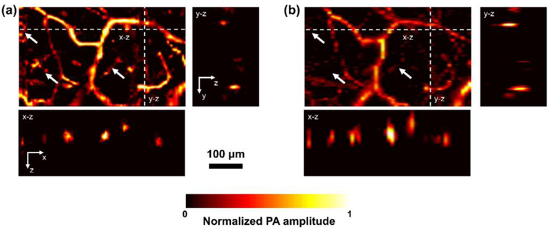
Side-by-side comparison of MAI-PAM and conventional PAM in the live mouse ear. (a–b), x–y maximum amplitude projection image, x–z and y–z cross-sectional image acquired by MAI-PAM and conventional PAM, respectively.
In summary, we have developed MAI-PAM for high-resolution imaging with micron-level isotropic spatial resolution in vivo. By using three illumination beams with difference incident angles, this imaging system is capable of realizing multi-view image acquisition and reconstruction without the rotation of imaging targets. We validated this technique both in phantom and in vivo. The phantom study shows that MAI-PAM has achieved a 10-fold improvement on axial resolution over conventional PAM. The in vivo study further confirms the improvement in resolution isotropy over conventional PAM. Future work includes quantification of the penetration depth, improvement of the imaging speed by applying optical-mechanical hybrid scan12 and implementation of comprehensive functional measurements including blood perfusion, oxygenation and flow with our previously developed multi-parametric analysis10,13.
Acknowledgments
Funding. This work is supported by the National Institutes of Health grants to SH (NS099261 and AG052062).
REFERENCES
- 1.Wang LV and Hu S, Science 335, 1458 (2012). [DOI] [PMC free article] [PubMed] [Google Scholar]
- 2.Maslov K, Zhang HF, Hu S, and Wang LV, Opt. Lett 33, 929 (2008). [DOI] [PubMed] [Google Scholar]
- 3.Dong B, Li H, Zhang Z, Zhang K, Chen S, Sun C, and Zhang HF, Optica (2015). [DOI] [PMC free article] [PubMed]
- 4.Wang T, Cao R, Ning B, Dixon AJ, Hossack JA, Klibanov AL, Zhou Q, Wang A, and Hu S, Appl. Phys. Lett 107, (2015). [Google Scholar]
- 5.Zhang C, Maslov K, Yao J, and V Wang L, J. Biomed. Opt 17, 116016 (2012). [DOI] [PMC free article] [PubMed] [Google Scholar]
- 6.Shelton RL, Mattison SP, and Applegate BE, J. Biophotonics (2014). [DOI] [PubMed]
- 7.Preibisch S, Amat F, Stamataki E, Sarov M, Singer RH, Myers E, and Tomancak P, Nat. Methods 11, (2014). [DOI] [PMC free article] [PubMed] [Google Scholar]
- 8.Zhu L, Li L, Gao L, and Wang LV, Optica 1, (2014). [DOI] [PMC free article] [PubMed] [Google Scholar]
- 9.Hu S, Maslov K, and Wang LV, Opt. Lett 36, 1134 (2011). [DOI] [PMC free article] [PubMed] [Google Scholar]
- 10.Ning B, Sun N, Cao R, Chen R, Kirk Shung K, Hossack JA, Lee J-M, Zhou Q, and Hu S, Sci. Rep 5, 18775 (2015). [DOI] [PMC free article] [PubMed] [Google Scholar]
- 11.Hai P, Yao J, Maslov KI, Zhou Y, and Wang LV, Opt. Lett (2014). [DOI] [PMC free article] [PubMed]
- 12.Wang T, Sun N, Cao R, Ning B, Chen R, Zhou Q, and Hu S, Neurophotonics 3, 045006 (2016). [DOI] [PMC free article] [PubMed] [Google Scholar]
- 13.Ning B, Kennedy MJ, Dixon AJ, Sun N, Cao R, Soetikno BT, Chen R, Zhou Q, Kirk Shung K, Hossack JA, and Hu S, Opt. Lett 40, 910 (2015). [DOI] [PubMed] [Google Scholar]