Abstract
Superconducting joints are one of the key components needed to make Ag-alloy clad Bi2Sr2CaCu2O8+x (Bi-2212) superconducting round wire (RW) successful for high-field, high-homogeneity magnet applications, especially for nuclear magnetic resonance (NMR) magnets in which persistent current mode (PCM) operation is highly desired. In this study, a procedure for fabricating superconducting joints between Bi-2212 round wires during coil reaction was developed. Melting temperatures of Bi-2212 powder with different amounts of Ag addition were investigated by differential thermal analysis (DTA) so as to provide information for selecting the proper joint matrix. Test joints of 1.3 mm dia. wires heat treated in 1 bar flowing oxygen using the typical partial melt Bi-2212 heat treatment (HT) had transport critical currents Ic of ~900 A at 4.2 K and self-field, decreasing to ~480 A at 14 T evaluated at 0.1 μV/cm at 4.2 K. Compared to the Ic of the open-ended short conductor samples with identical 1 bar HT, the Ic values of the superconducting joint are ~20% smaller than that of conductor samples measured in parallel field but ~20% larger than conductor samples measured in perpendicular field. Microstructures examined by scanning electron microscopy (SEM) clearly showed the formation of a superconducting Bi-2212 interface between the two Bi-2212 round wires. Furthermore, a Bi-2212 RW closed-loop solenoid with a superconducting joint heat treated in 1 bar flowing oxygen showed an estimated joint resistance below 5×10⁻¹² Ω based on its field decay rate. This value is sufficiently low to demonstrate the potential for persistent operation of large inductance Bi-2212 coils.
1. Introduction
Currently, there are three types of high temperature superconducting (HTS) conductors available, Bi2Sr2CaCu2O8+x (Bi-2212), Bi2Sr2Ca2Cu3O8+x (Bi-2223) and (Rare Earth)Ba2Cu3O7-x (REBCO) [1]. As the only HTS cuprate in a round wire (RW) form, Ag-alloy clad Bi-2212 conductor can be delivered in a twisted configuration with multiple multi-filamentary architectures [2]. Advantages of round wire Bi-2212 for solenoid magnet builders are ease of applying conductor insulation and coil winding and for high field accelerator magnets, its ease of cabling [3–6]. Twisting Bi-2212 RW is also possible which reduces hysteretic charging losses. Being multi-filamentary and electro-magnetically isotropic, Bi-2212 RW magnets are not expected to be significantly affected by screening currents that are induced by the large radial field components in solenoids wound with anisotropic tape conductors [7–9]. Furthermore, Bi-2212 RW exhibits a high irreversibility field beyond 100 T at 4.2 K [2, 10]. The overpressure (OP) heat treatment (HT), recently developed by our group at the National High Magnetic Field Laboratory (NHMFL), dramatically increases the whole-wire, engineering current density (Je) of Bi-2212 RW. Je of more than 600 A/mm2 (at 4.2 K and 20 T) has been achieved after 100 bar OP processing [2]. With all of these intrinsically beneficial properties and recent HT processing progress, Bi-2212 RW has become a competitive conductor candidate for high-field, high-homogeneity magnetic field applications, especially for nuclear magnetic resonance (NMR) and particle accelerator magnets [11–13].
Bi-2212 RW is fabricated by the powder-in-tube (PIT) method, which now reproducibly yields lengths of significantly more than 1 Km in a billet design that can be scaled up [14]. However, several kilometers of conductor are required to build larger high field magnet systems, which are usually designed in a modular pattern with multiple superconducting coils for optimal field homogeneity and stress management [15]. Thus, there is a need for electrical joints to connect individual wire lengths within a single coil, or to connect multiple coil sections within the magnet. In general, jointing techniques can produce either resistive or superconducting joints. Resistive jointing methods are usually easy to accomplish using conventional soldering methods, but superconducting joints have become a standard for high field Nb-based NMR magnets, which require excellent field stability to within a few ppb per hour [16]. Since practical NMR magnets large inductances of order 100 H, the total resistances of all joints can be up to ~10−11 Ω and still meet stringent field stability targets. Many power supplies provide some degree of current ripple and drift that make it difficult to achieve the highest degree of field stability when magnets are operated in driven current mode (DCM). In addition, stringent requirements for a highly stable power supply will increase the cost of the NMR system. Therefore, it is highly desirable that HTS NMR magnets be capable of operating in persistent current mode (PCM) too. Superconducting joints are crucial to enable persistent mode operation and researches on superconducting joint techniques between different technological superconductors have been extensively carried out over the last few decades, though details are often not published in view of their commercial value. Recently, Brittles et al. [17] have comprehensively reviewed superconducting jointing techniques between the five major technological superconductors: Nb-Ti, Nb3Sn, MgB2, Bismuth Strontium Calcium Copper Oxide (BSCCO) and REBCO.
Currently, practical HTS superconducting magnets are not operated in persistent mode. Considering the brittle mechanical properties and the chemically sensitive nature of HTS ceramic filaments, the difficulty of developing reliable and practical HTS superconducting joint techniques is clear. For mono and multi-filamentary Bi-2223 tape conductors, some methods were developed that are claimed to make superconducting joints [18–21], for example cold pressing followed by post-annealing and diffusion bonding. However, the transport critical current (Ic) of these joints was usually strongly degraded. Also since the technique requires a long post-anneal after coil winding, such a joint technique is rather impractical for real coils. For REBCO coated conductors, a persistent superconducting joint has been reported by Park et al. [22]. This approach, however, is also complicated, because it involves laser drilling to allow oxygen access to the REBCO layer followed by a long oxygenation anneal. For Bi-2212 RW conductors, very little literature or detail on superconducting joints can be found [23]. Since Bi-2212 coils generally require the Wind and React (W&R) approach [24], it would be beneficial if joints could be heat treated together with the coil winding pack, thus allowing the superconducting joints to be fully formed during the typical Bi-2212 HT process. In this paper, such a practical superconducting joint design for Bi-2212 RWs is reported [25]. The technique described is one that allows a native Bi-2212 to Bi-2212 wire joint to be formed while the coil itself undergoes heat treatment.
2. Experimental details
To enable a W&R joint, a melting temperature study of Bi-2212 granulate powder with different Ag additions was first carried out. Then, joints were fabricated, heat treated and characterized. After some optimization, a closed-loop coil consisting of a small Bi-2212 solenoid and a Bi-2212 superconducting joint was fabricated and heat treated in 1 bar flowing oxygen, and the effective coil resistance including the joint and flux creep resistance was estimated from its field decay rate [26].
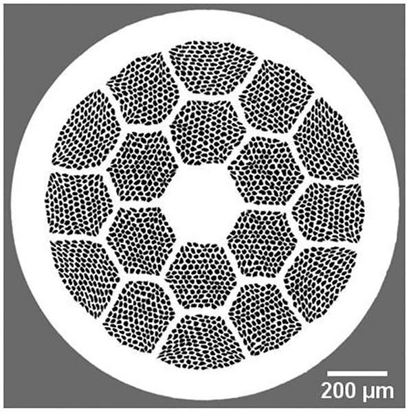
Standard PIT Bi-2212 multi-filamentary RW, manufactured by Oxford Superconducting Technology (OST), was used for both short samples and coils. The as-drawn wire, with a diameter of 1.3 mm, is composed of 18×121 Bi-2212 filaments embedded in an Ag stabilizer with an outer sheath of Ag-0.2 wt.% Mg alloy. The transverse cross section of the as-drawn Bi-2212 RW is shown in figure 1.
Figure 1.
Light microscope image of a transverse cross section of an as-drawn 1.3 mm diameter Bi-2212 RW manufactured by OST. It is a double stack wire composed of 18 bundles of first stack 121 Bi-2212 filaments.
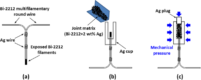
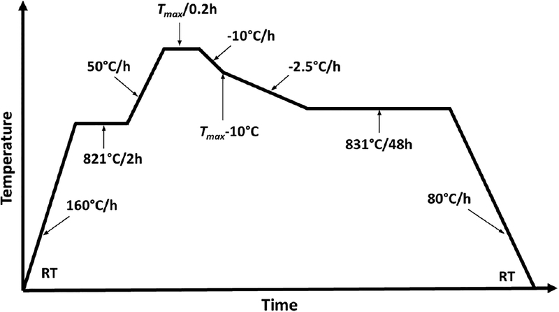
Figure 2 illustrates the Bi-2212 superconducting joint fabrication procedure. First, we prepare two L-shaped bent pieces of as-drawn Bi-2212 RWs with a bend diameter of 15 mm, which resemble the wire sections as the wire enters and leaves the winding near the electrical joint. One end (8–10 mm long) of each wire was dipped in an etchant (30 wt.% ammonia: 30 wt.% hydrogen peroxide=5:2 in volume) until the outer Ag alloy sheath was removed, exposing the Bi-2212 filaments. The two etched wires were then placed in the “praying hand” configuration of figure 2(a), and the Bi-2212 filaments of the two wires were placed in close contact and secured with Ag wires wrapped around the contact area. A 24 mm long cylindrical Ag piece with a diameter of 8 mm was prepared for hosting the joint and its connecting matrix. One 7 mm diameter hole was drilled to a depth of 20 mm from one side of the Ag cylinder, and two 1.3 mm diameter through holes were drilled from the other side to accept the wires. After inserting the joint into the Ag cup through the two small holes, pre-mixed Bi-2212 powder (2 wt.% Ag) was poured into the Ag cup from the open end, as shown in figure 2(b). An Ag plug was then used to compress the powder mixture and seal the open end of the Ag cup, which was then uniaxially pressed at ~700 MPa, as shown in figure 2(c). In this way, the loss of Bi-2212 components during the HT can be reduced and the powder density greatly increased, both of which are crucial for forming a continuous superconducting network between the two Bi-2212 RWs. Finally, the joint was heat treated in 1 bar flowing oxygen using the typical Bi-2212 RW schedule. Details of the typical Bi-2212 RW HT schedule are illustrated in figure 3.
Figure 2.
Fabrication procedure for a superconducting joint between Bi-2212 round wires.
Figure 3.
The HT profile used for HT of Bi-2212 RW in our experiments.
After full partial melt Bi-2212 HT, the transport properties of joints were evaluated using the standard four-point method at 4.2 K and background magnetic fields from 0 T to 14 T. A maximum current of 1400 A could be supplied by employing four Sorensen 350 A DC power supplies. The transport Ic properties of joints were characterized with a 1 μV/cm criterion, and the results were compared with that of open-ended short conductor samples that went through an identical 1 bar HT. After evaluating the transport properties, some joints were cut and polished, and the microstructures were examined by scanning electron microscopy (SEM).
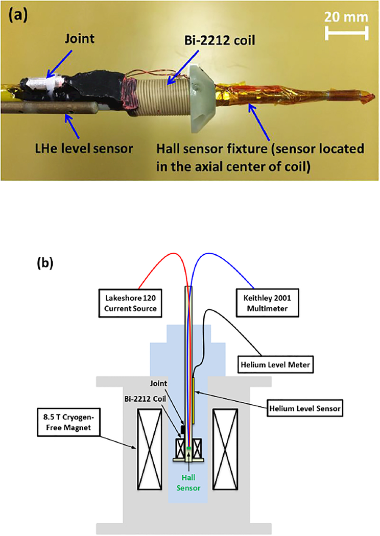
To demonstrate potential persistent operation of Bi-2212 coils, a Bi-2212 solenoid with integrated Bi-2212 superconducting joint was fabricated and evaluated by the field decay method. The coil employed 1.3 mm diameter Bi-2212 RW insulated with ~30 μm thick TiO2-polymer coating at the NHMFL [27, 28]. The coil was wound on a pre-oxidized, demountable Inconel 600 alloy mandrel. To reduce potential chemical reactions between Bi-2212 and Inconel, the pre-oxidized mandrel was sprayed with zirconia prior to coil winding. The coil consisted of 2 layers, each with 24 turns, with a total conductor length of 2.7 m. The inner diameter, outer diameter and height of the coil are 14.5 mm, 20.3 mm and 33.3 mm, respectively. The self-inductance of the coil was calculated to be 15.3 μH, which was confirmed by inductance measurement with a BK precision 889A LCR meter. Following the fabrication steps illustrated in figure 2, a Bi-2212 superconducting joint was made between the two terminals of the coil to form a closed-loop circuit. Then, the closed-loop coil was heat treated in 1 bar flowing oxygen using the schedule illustrated in figure 3 except that a slow 20 °C h−1 ramp was applied from room temperature (RT) to 450 °C to slowly decompose and burn off the organic components of the insulation layer [29]. After the typical Bi-2212 HT reaction, the coil was transferred from the Inconel 600 mandrel to a G-10 mandrel in order to achieve mechanical decoupling between the coil winding pack and the bore tube and to avoid any potential perturbation to the Hall sensor reading due to potential spin glass properties below 6 K in the Inconel 600 [30]. After that, the coil was impregnated with Stycast 1264 epoxy resin, and the joint region was filled with black Stycast 2850 epoxy resin. After fully curing the epoxy, a Hall sensor (AREPOC LHP-NA) was mounted in the physical center of the coil, as is sketched in figure 4(a). Last, the probe was inserted into a cryostat situated in the warm bore of an 8.5 T cryogen-free superconducting magnet with the Bi-2212 coil and the background magnet having the same physical center. During the field decay test, the Hall voltages and the shunt voltages of the background magnet were monitored by Keithley 2001 multimeters, as is illustrated in figure 4(b).
Figure 4.
(a) Picture of the closed-loop Bi-2212 solenoid and its Bi-2212 superconducting joint. (b) Schematic illustration of the field decay test.
3. Results
3.1. Choice of matrix for the superconducting joints
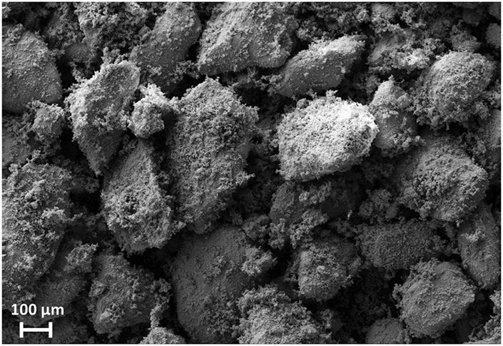
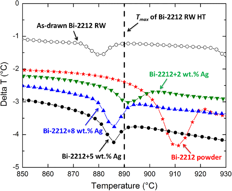
To build a continuous superconducting network between the Bi-2212 filaments during the Bi-2212 partial melt HT, we chose Bi-2212 granulate powder manufactured by Nexans SuperConductors as the joint matrix. Its particle size is normally in the range from 100 μm to 500 μm, as a typical SEM image in figure 5 shows. Since joints are designed to go through the HT together with the Bi-2212 coil, it is essential that the melting of the joint matrix should occur at the temperature of the Bi-2212 HT. To verify this, the melting temperatures of Bi-2212 RW and Bi-2212 granulate powder were studied by differential thermal analysis (DTA) performed at a 10 °C min−1 ramp rate in flowing oxygen. The DTA data, shown in figure 6, reveal endothermic peaks corresponding to the melting of constituents in the mixtures. The partial melting onset temperature of Bi-2212 RW was found to be 873 °C, while the melting onset temperature of pure Bi-2212 granulate powder was found to be 902 °C, significantly higher than the maximum temperature (Tmax) 890 °C of the typical Bi-2212 HT employed that is shown in figure 3. We therefore concluded that pure Bi-2212 granulate powder could not be directly employed as the joint matrix material.
Figure 5.
SEM image of Bi-2212 granulate powder manufactured by Nexans SuperConductors. Typically, the particle size is in the range from 100 μm to 500 μm. Owing to the micaceous structure of the Bi-2212, these large particles break down during wire drawing to achieve final Bi-2212 filaments with diameters of ~15 μm.
Figure 6.
DTA melting temperature study on various Bi-2212 powder with Ag additions. The endothermic peaks of DTA curves clearly illustrate the melting temperatures of the mixtures, while the dashed vertical line indicates the maximum temperature (Tmax) 890 °C of the typical Bi-2212 RW HT shown in figure 3.
It has been reported that the melting temperature of Bi-2212 is closely related to its foreign additions, such as magnesium oxide (MgO), cerium oxide (CeO2) and Ag [31]. As is well known, Ag is non-magnetic and non-poisoning when in contact with Bi-2212 [32, 33]. Furthermore, the reactions between Ag and the Bi-2212 melt have been investigated [34, 35]. The results indicate that the Ag-CuO reaction occurs below the pure Bi-2212 melting point during the Bi-2212 HT. Based on these previous results, we added high purity Ag powder manufactured by Alfa Aesar with average particle size 1.3–3.2 μm to the Bi-2212 granulate powder to reduce the melting temperature. The DTA curves in figure 6 show the endothermic peaks with 2–8 wt.% Ag additions to the Bi-2212 powder and make it clear that the melting temperature decreases with Ag additions. When the Ag concentration exceeds 2 wt.%, the melting onset temperature drops below 890 °C to reach a concentration-independent limit of 880 °C with ~5 wt.% Ag concentration. Accordingly, we chose Bi-2212 powder with 2 wt.% Ag as the joint matrix so as to give a melting onset at 883 °C, as shown in figure 6.
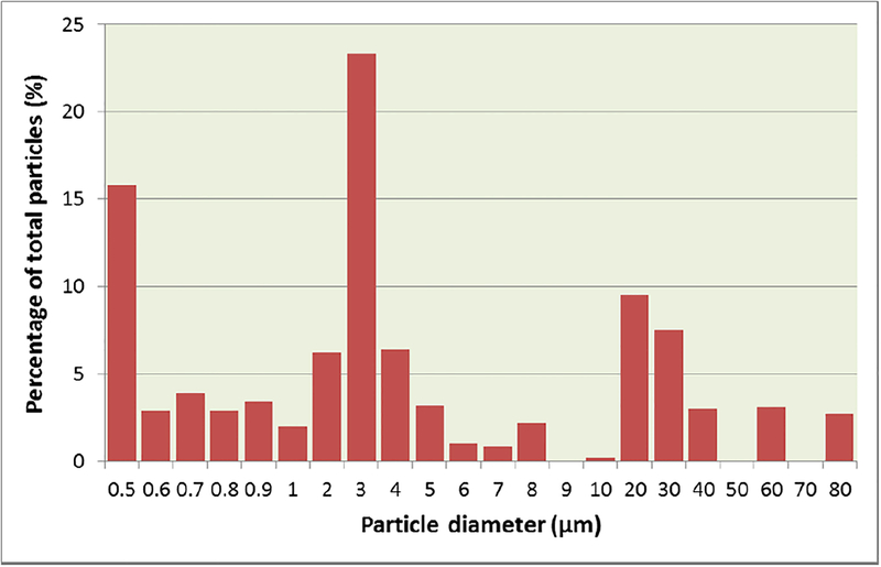
Fine powder particle size is a key to achieve high powder packing density. To check the quality of the matrix material after dry milling, the particle size distribution was analyzed using a particle size analyzer (HORIBA CAP-700). The results indicate that all the particles are below 100 μm, and about 75% are below 10 μm, as shown in figure 7.
Figure 7.
Particle size distribution of joint matrix (Bi-2212 powder with 2 wt.% Ag addition). After milling, all the particles are below 100 μm, and about 75% are below 10 μm.
3.2. Transport properties of the superconducting joints
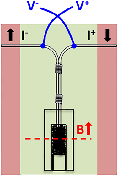
To evaluate the joint transport properties, four-point measurements were carried out. Joints were fabricated with 10 mm long sections of filaments exposed prior to heat treatment at 1 bar oxygen pressure. After the HT, the two free ends of each joint were soldered to two copper leads insulated by a G-10 plate, and one pair of voltage taps was also soldered to the joint with the magnetic field direction parallel to the wire axes for probe under transport tests, as sketched in figure 8.
Figure 8.
A schematic illustration of the test setup for measuring joint transport properties at 4.2 K in magnetic fields. The field direction is parallel to the wire axis at the joint section, as indicated by the red arrow. The background field center lies at the physical center of the exposed Bi-2212 ends, as indicated by the red dashed line.
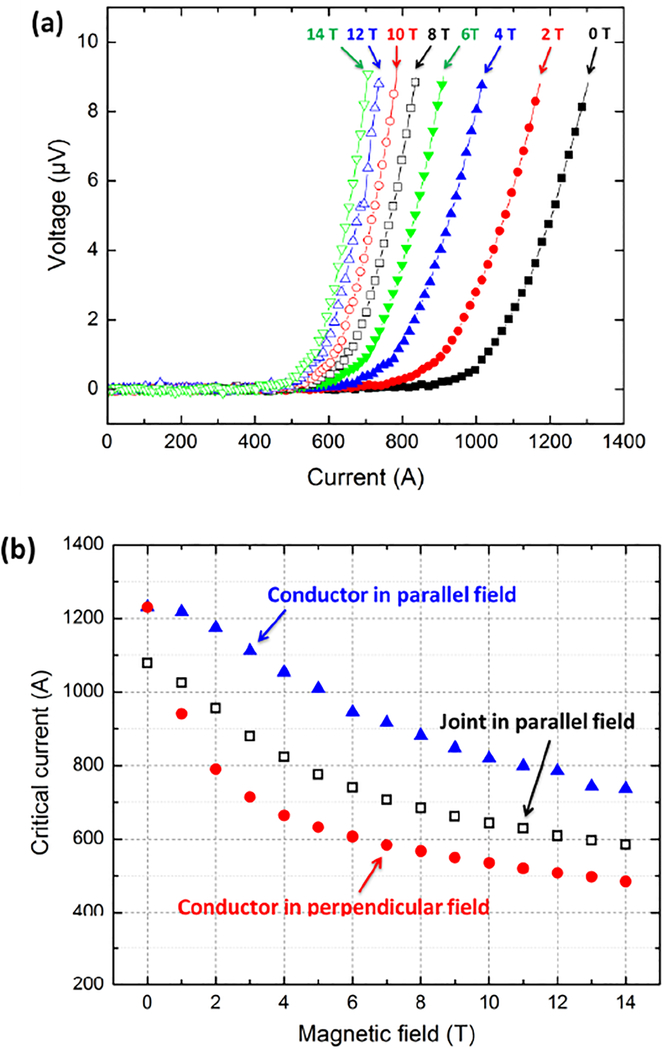
As shown in figure 9(a), the test joint possessed good superconducting properties at 4.2 K at all fields up to 14 T without evident early-onset resistance or excess Joule heating. With a criterion of 0.1 μV/cm and a voltage tap length of 20 mm, a critical supercurrent of ~900 A was achieved at self-field, which decreased to ~480 A at 14 T. The power-law transition from the superconducting state to the normal state was very smooth but the measured n-value of ~8 was, however, smaller than the usual range of 18–20. At 1 μV/cm, the Ic(H) of test joints are compared in figure 9(b) with identically heat treated, open-ended short samples evaluated with the magnetic field both perpendicular and parallel to the conductor length. The Ic values of the joint are ~20% smaller than that of conductor samples measured in parallel field but ~20% larger than conductor samples measured in perpendicular field.
Figure 9.
(a) V-I curves of a typical Bi-2212 superconducting joint at 4.2 K and magnetic fields of up to 14 T. (b) Comparison of Ic properties at 4.2 K between open-ended short Bi-2212 conductor samples and the Bi-2212 superconducting joint. Joint and conductor samples were both reacted in a total pressure of 1 bar flowing oxygen. For the joint, the field direction is parallel to the joint length section as illustrated in figure 8. For the short samples, the field direction is either parallel or perpendicular to the sample length.
3.3. Microstructure of the superconducting joints
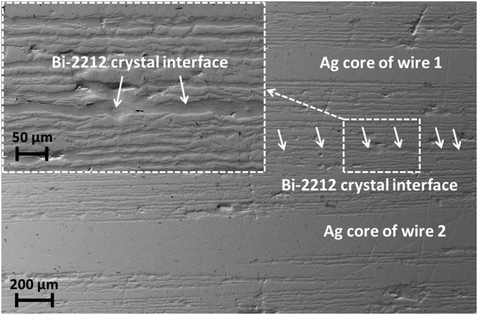
After evaluating the transport properties, some Bi-2212 superconducting joints were cut and polished. Figure 10 shows a longitudinal cross section SEM image of a typical joint. The microstructure is quite dense and shows close alignment of the two wires. We conclude that the Ag addition uniformly dissolved in the Bi-2212 liquid during the partial melt and that the interface between the two wires was enclosed with well textured Bi-2212 crystal colonies, as indicated by the white arrows in figure 10. The outcome is a well-connected superconducting network between Bi-2212 filaments. It is evident that the joint matrix material melted and smoothly solidified during the Bi-2212 HT, a result that indicates that Bi-2212 superconducting joints can be achieved during typical HT processing of Bi-2212 coils.
Figure 10.
SEM image of a longitudinal cross section of a typical Bi-2212 superconducting joint. A superconducting Bi-2212 crystal interface between Bi-2212 round wires is indicated by the white arrows. A magnified view of the Bi-2212 interface is also provided in the inset.
3.4. Characterization of the superconducting joints with the field decay method
The resistance sensitivity of the four-point measurement is of order 10−11 Ω and therefore cannot be used as a strict criterion of a persistent superconducting joint [16]. More usually, a field decay method is employed to evaluate superconducting joints [26]. For example, Brittles et al. [36] recently reported the use of a SQUID magnetometer to carry out rapid field decay tests with better resolution.
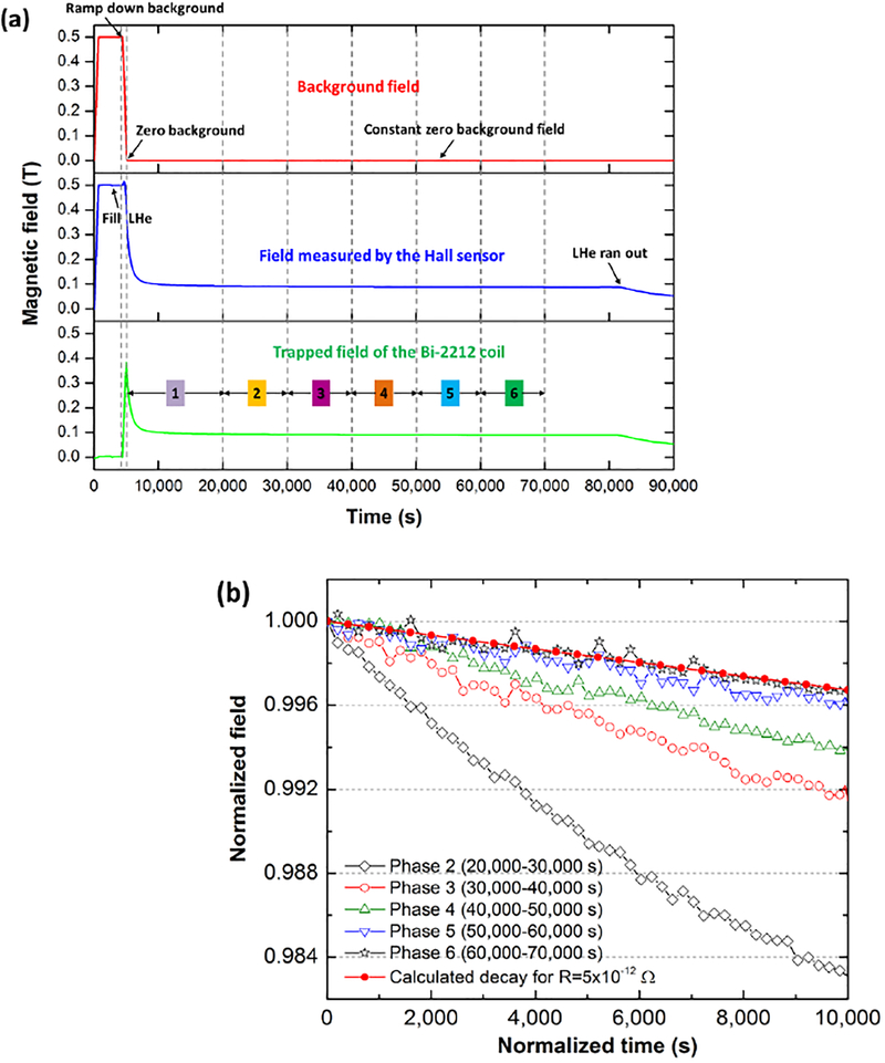
To demonstrate persistent operation, a field decay test for the Bi-2212 closed-loop coil was setup as illustrated in figure 4(b). The background magnet was ramped up to 0.5 T at a ramp rate of ~8.38×10⁻⁴ T/s and then held steady while the Bi-2212 coil was field cooled down to 4.2 K by immersion in liquid helium after starting above critical temperature (Tc). When the Hall sensor signals stabilized (5000±0.1 G), the background magnet was ramped down to zero current at 8.38×10⁻⁴ T/s. A persistent current was induced in the coil and its associated field was continuously recorded until the helium of the insert cryostat ran out about 22 h later.
The results of the test are presented in figure 11(a) with the decay behavior divided into 6 phases. When the background field was ramped down to zero, a magnetic field of ~0.38 T, corresponding to a current of 271 A, was initially induced into the Bi-2212 coil. Considering the low resistance of the Bi-2212 superconducting joint and the self-inductance of the Bi-2212 solenoid, the closed-loop coil circuit is a first-order resistor-inductor (R-L) circuit, and the relaxation of the trapped field is ideally the zero-input response of the R-L circuit. However, the relaxation of the trapped field did not occur in a purely exponential way. As shown in figure 11(a), the trapped field decayed rather quickly to ~0.1 T in the first 5000 s. In phase 1, we believe that there was an inhomogeneous current distribution crossing some low resistance ohmic paths across the Ag conductor sheath, which is a well-known settling phenomenon [17]. In the subsequent 10,000 second time slices (phases 2–6), the trapped field decayed much more slowly, the rate becoming continuously slower as shown in figure 11(b). In phase 6 (60,000–70,000 s), the decay behavior is almost purely exponential with a calculated resistance of 5×10⁻¹² Ω.
Figure 11.
(a) Evolution of magnetic field measurements during the field decay test, which lasted ~23 hours until the LHe ran out. The magnetic field in the physical center of the background and Bi-2212 insert coils was measured by a Hall sensor. (b) The decay behavior of the normalized Bi-2212 coil trapped field in 5 different phases shown in figure 11(a). The magnetic fields of each phase (10,000 s long) are normalized by dividing the starting field value of each phase, and the time of each phase is normalized by subtracting the first time value of each phase. Assuming a coil self-inductance of 15.3 μH and a joint resistance of 5×10⁻¹² Ω, a purely exponential field decay of the R-L circuit was also calculated. This fits the experimental decay rate of the last phase (phase 6) very well.
4. Discussion
In this study, the fabrication of a superconducting joint between Bi-2212 round wires was presented, as illustrated in figure 2. Subsequent to chemical etching, joint assembly and mechanical densification of the Bi-2212 powder (2 wt.% Ag) surrounding the wires, the joint was heat treated in 1 bar flowing oxygen using a standard Bi-2212 RW HT profile (figure 3). This resulted in a native Bi-2212 superconducting joint without introduction of any other material. The joint fabrication procedure is practical and fully compatible with coil manufacture.
The development of a suitable superconducting matrix is a key component of Bi-2212 superconducting joints. Since the joint matrix has to go through the typical Bi-2212 HT, several challenges are posed. The joints must be able to withstand 890 °C, which excludes the use of conventional eutectic superconducting solders with low melting temperatures [17]. The DTA data of figure 6 show that the melting temperature of pure Bi-2212 granulate powder is significantly higher than the peak processing temperature of the Bi-2212 coil but that adding 2 wt.% Ag reduces the melting onset temperature to 883 °C. This composition was selected as the joint matrix. Such a powder is clearly chemically compatible with Bi-2212 filaments and avoids large mismatch of the thermal expansion coefficients between joint and Bi-2212 filaments which might lead to delamination of the superconducting interface [17]. Figure 10 shows an SEM image of a longitudinal cross section of a typical Bi-2212 superconducting joint, which went through several thermal cycles during transport measurements at 4.2 K. It clearly shows a Bi-2212 superconducting interface between the two Bi-2212 round wires without any evident delamination. In summary all data obtained in this study are consistent with the conclusion that Bi-2212 powder with 2 wt.% Ag addition is a suitable matrix material for making Bi-2212 superconducting joints.
The joint transport characteristics are one of the most critical properties. The data shown in figure 9(a) present the transport properties of a typical Bi-2212 superconducting joint at 4.2 K and magnetic fields from 0 T to 14 T. In general, the joints all had good superconducting properties without evident ohmic components to the traces. With a criterion of 0.1 μV/cm, a critical supercurrent of ~900 A was achieved at self-field, and it gradually decreased as the external magnetic field increased in a manner almost identical to the Ic(H) characteristics of the wire alone. In high field superconducting magnets, superconducting joints are normally located at the ends of the superconducting coils, where the radial field is large but the total field is much smaller than the central field. Joints with significantly weaker transport properties than the wires themselves will introduce many constraints on where the joints can be placed and magnetic shielding may be required [37]. The V-I curves of the superconducting joints show relatively low n-values (8–10, rather than ~20 for wires) which may indicate either a lowered intergranular connectivity in the Bi-2212 bulk connecting the two wires or an otherwise less than full connectivity [38]. The transport Ic data shown in figure 9(b) clearly indicate that ~20% Ic degradation was observed in the Bi-2212 superconducting joint compared with the 1 bar reacted open-ended conductor sample (measured in parallel field). However, the Ic values of the superconducting joint are ~20% higher than the 1 bar conductor sample measured in perpendicular field. This implies that the performance of a solenoid coil would not be particularly limited by joint performance since coil conductors are mostly exposed to perpendicular magnetic field and the magnetic field of joint location is typically much smaller than the coil peak field.
Measuring the decay of a trapped field in a coil is a classic way to characterize superconducting joints. With this method, we demonstrated the potential for persistent operation of a Bi-2212 coil. As shown in figure 11(a), once the external field was ramped down to zero, the trapped field decayed rapidly from ~0.38 T to ~0.1 T in about 5000 s. This transient behavior with a high initial field decay rate is a well-known settling phenomenon, which is generally thought to be caused by redistribution of initially inhomogeneous current in the superconducting wire cross section including current flow across the resistive matrix [17]. Since the total dissipation includes dissipation due to any ohmic circuit component, as well as flux creep within the conductor [39], indeed the relaxation of the trapped field was not purely exponential but it did slow with time as shown in figure 11(b). In phase 6, the coil decay resistance was estimated to be below 5×10⁻¹² Ω, which is sufficiently low to demonstrate the potential for persistent operation of large inductance Bi-2212 coils, e.g., for an 100 H magnet with only one joint, the time constant τ (τ=L/R) is ~5×10⁹ hours. It was observed that when the field stabilized at ~0.1 T, the corresponding current flowing in the closed-loop coil is about 71 A, which is much smaller than the typical Bi-2212 superconducting joint Ic (1079 A) at self-field and 4.2 K. The low induced current may be attributed to various factors. First, there is some current redistribution causing ohmic dissipation immediately after the coil was inductively charged. Second, after the wire sheath was chemically etched away to expose the Bi-2212 filaments as shown in figure 2(a), some filaments might be damaged in the joint fabrication steps due to the fragile, only loosely-packed powder state. In other words, the superconducting fill factor of the two jointed conductors could be significantly less than in the as-drawn conductors. Third, the Bi-2212 closed-loop coil for the field decay test was reacted in 1 bar flowing oxygen, and it potentially contained many gas bubbles inside the conductors though no evident leaks were observed. These bubbles lead to Ic degradation compared to 1 bar reacted open-end short samples [2]. In short it seems that we must further perfect the joint in order to achieve full critical current. Nevertheless, it does appear that we have succeeded in making a native superconducting joint out of Bi-2212 wires that is compatible with coil fabrication and heat treatment. This capability further adds to the full suite of capabilities exhibited by Bi-2212 round wire which is by far the closest analog to a Nb-Ti or Nb3Sn conductor in being round, multifilament, twisted and isotropic in its macroscopic state.
5. Summary
We developed a native superconducting joint between Bi-2212 round wires for potential persistent operation of Bi-2212 coils. The joint fabrication procedure is effective and practical, enabling Bi-2212 superconducting joints to be achieved during a standard HT of Bi-2212 coils. The Bi-2212 superconducting joints possessed good superconducting properties. Using a 0.1 μV/cm criterion, a critical supercurrent of ~900 A was achieved at 4.2 K and self-field which decreased to ~480 A at 14 T. Compared to the Ic of the open-ended short conductor samples with identical 1 bar HT, the Ic values (1 μV/cm) of the superconducting joint are ~20% smaller than that of conductor samples measured in parallel field but ~20% larger than conductor samples measured in perpendicular field. SEM analysis clearly presented the formation of a Bi-2212 superconducting interface between the two wires. In the field decay test, the resistance of a Bi-2212 superconducting joint was estimated to be below 5×10⁻¹² Ω at 4.2 K and self-field, which is sufficiently low to demonstrate the possibility of persistent operation of large inductance Bi-2212 coils.
Acknowledgements
The authors are grateful to Timothy Cross, Lucio Frydman, William Brey and Seungyong Hahn of NHMFL-FSU for many valuable discussions. We also would like to express thanks to Yibing Huang and Hanping Miao from Oxford Superconducting Technology for providing Nexans Bi-2212 granulate powder. Technical support from Lamar English, George Miller and Ashleigh Francis at NHMFL-FSU is also greatly acknowledged. This work was supported by the US Department of Energy Office of High Energy Physics under grant number DE-SC0010421, by the National High Magnetic Field Laboratory which is supported by the National Science Foundation under NSF/DMR-1157490, by the State of Florida, and by the National Institute of General Medical Sciences of the National Institutes of Health under Award Number R21GM111302. The content is solely the responsibility of the authors and does not necessarily represent the official views of the National Institutes of Health.
References
- [1].Maeda H and Yanagisawa Y, 2013. Recent developments in high-temperature superconducting magnet technology IEEE Trans. Appl. Supercond 24 4602412 [Google Scholar]
- [2].Larbalestier DC, Jiang J, Trociewitz UP, Kametani F, Dalban-Canassy M, Matras M, Chen P, Craig NC, Lee PJ and Hellstrom EE 2014. Isotropic round-wire multifilament cuprate superconductor for generation of magnetic fields above 30 T Nat. Mater 13 375–81 [DOI] [PubMed] [Google Scholar]
- [3].Hasegawa T, Ohtani N, Koizumi T, Aoki Y, Nagaya S, Hirano N, Motowidlo L, Sokolowski RS, Scanlan RM, Dietderich DR and Hanai S 2001. Improvement of superconducting properties of Bi-2212 round wire and primary test results of large capacity Rutherford cable IEEE Trans. Appl. Supercond 11 3034–7 [Google Scholar]
- [4].Godeke A, Cheng D, Dietderich DR, English CD, Felice H, Hannaford CR, Prestemon SO, Sabbi G, Scanlan RM, Hikichi Y, Nishioka J and Hasegawa T 2008. Development of wind-and-react Bi-2212 accelerator magnet IEEE Trans. Appl. Supercond 18 516–9 [Google Scholar]
- [5].Godeke A, Cheng DW, Dietderich DR, Hannaford CR, Prestemon SO, Sabbi G, Wang XR, Hikichi Y, Nishioka J and Hasegawa T 2009. Progress in wind-and-react Bi-2212 accelerator magnet technology IEEE Trans. Appl. Supercond 19 2228–31 [Google Scholar]
- [6].Godeke A, Cheng D, Dietderich DR, Ferracin P, Prestemon SO, Sabbi G and Scanlan RM 2007. Limits of NbTi and Nb3Sn, and development of W&R Bi-2212 high field accelerator magnets IEEE Trans. Appl. Supercond 17 1149–52 [Google Scholar]
- [7].Amemiya N and Akachi K 2008. Magnetic field generated by shielding current in high Tc superconducting coils for NMR magnets Supercond. Sci. Technol 21 095001 [Google Scholar]
- [8].Koyama Y, Takao T, Yanagisawa Y, Nakagome H, Hamada M, Kiyoshi T, Takahashi M and Maeda H 2009. Towards beyond 1 GHz NMR: Mechanism of the long-term drift of screening current-induced magnetic field in a Bi-2223 coil Physica C 469 694–701 [Google Scholar]
- [9].Yanagisawa Y, Nakagome H, Uglietti D, Kiyoshi T, Hu R, Takematsu T, Takao T, Takahashi M and Maeda H 2010. Effect of YBCO-coil shape on the screening current-induced magnetic field intensity IEEE Trans. Appl. Supercond 20 744–7 [Google Scholar]
- [10].Trociewitz UP, Schwartz J, Marken K, Miao H, Meinesz M and Czabaj B 2006. Bi-2212 superconductors in high field applications NHMFL Reports 2006 vol 13, p 31 [Google Scholar]
- [11].Markiewicz WD, Miller JR, Schwartz J, Trociewitz UP and Weijers HW 2006. Perspective on a superconducting 30 T/1.3 GHz NMR spectrometer magnet IEEE Trans. Appl. Supercond 16 1523–6 [Google Scholar]
- [12].Weijers HW, Trociewitz UP, Marken K, Meinesz M, Miao H and Schwartz J 2004. The generation of 25.05 T using a 5.11 T Bi2Sr2CaCu2Ox superconducting insert magnet Supercond. Sci. Technol 17 636–44 [Google Scholar]
- [13].Rossi L. et al. The EuCARD-2 future magnets European collaboration for accelerator-quality HTS magnets. IEEE Trans. Appl. Supercond. 2015;25 4001007. [Google Scholar]
- [14].Huang Yibing, Oxford Superconducting Technology, private communication
- [15].Iwasa Y 2009. Case Studies in Superconducting Magnets: Design and Operational Issues 2nd edn (Springer, New York: ) [Google Scholar]
- [16].Jaroszynski J. Race against time: resistance of superconducting joints measurements. Supercond. Sci. Technol. 2015;28 010501. [Google Scholar]
- [17].Brittles GD, Mousavi T, Grovenor CRM, Aksoy C and Speller SC 2015. Persistent current joints between technological superconductors Supercond. Sci. Technol 28 093001 [Google Scholar]
- [18].Tkaczyk JE, Arendt RH, Bednarczyk PJ, Garbauskas MF, Jones BA, Kilmer RJ and Lay KW 1993. Superconducting joints formed between powder-in-tube Bi2Sr2Ca2Cu3Oz/Ag tapes IEEE Trans. Appl. Supercond 3 946–948 [Google Scholar]
- [19].Kim JH, Kim KT, Joo J and Nah W 2002. A study on joining method of Bi-Pb-Sr-Ca-Cu-O multifilamentary tape Physica C 372–376 909–912 [Google Scholar]
- [20].Guo W, Zou G, Wu A, Wang Y, Bai H and Ren J 2009. Superconducting joint of Bi-2223/Ag superconducting tapes by diffusion bonding Physica C 469 1898–1901 [Google Scholar]
- [21].Guo W, Zou G, Wu A, Zhou F and Ren J 2010. Fabrication of joint Bi-2223/Ag superconducting tapes with BSCCO superconducting powders by diffusion bonding Physica C 470 440–443 [Google Scholar]
- [22].Park Y, Lee M, Ann H, Choi YH and Lee H 2014. A superconducting joint for GdBa2Cu3O7-δ-coated conductors NPG Asia Mater 6 e89 [Google Scholar]
- [23].Hase T, Murakami Y, Hayashi S, Kawate Y, Kiyoshi T, Wada H, Sairote S and Ogawa R 2000. Development of Bi-2212 multifilamentary wire for NMR usage Physica C 335 6–10 [Google Scholar]
- [24].Godeke A, Acosta P, Cheng D, Dietderich DR, Mentink MGT, Prestemon SO, Sabbi GL, Meinesz M, Hong S, Huang Y, Miao H and Parrell J 2010. Wind-and-react Bi-2212 coil development for accelerator magnets Supercond. Sci. Technol 23 034022 [Google Scholar]
- [25].Trociewitz UP, Chen P, Hilton DK, Abraimov DV, Starch WL, Larbalestier DC, Jiang J, Hellstrom EE, Bosque ES and Matras M, “A Practical Superconducting Electrical Joint Design for High Temperature Superconducting Bi2Sr2CaCu2O8+x (B-2212) Round Wire” (U.S. Patent pending, FSU Ref.: 15–131, March-2015)
- [26].Iwasa Y 1976. Superconducting joint between multifilamentary wires 2. Joint evaluation technique Cryogenics 16 217–219 [Google Scholar]
- [27].Kandel H, Lu J, Jiang J, Chen P, Matras M, Craig N, Trociewitz UP, Hellstrom E and Larbalestier D 2015. Development of TiO2 electrical insulation coating on Ag-alloy sheathed Bi2Sr2CaCu2O8-x round wire Supercond. Sci. Technol 28 035010 [Google Scholar]
- [28].Lu J, McGuire D, Kandel H, Xin Y, Chen P, Jiang J, Trociewitz UP, Hellstrom E and Larbalestier D 2016. Ceramic Insulation of Bi2Sr2CaCu2O8-x Round Wire for High-Field Magnet Applications IEEE Trans. Appl. Supercond 26 7701005 [Google Scholar]
- [29].Chen P, Trociewitz UP, Dalban-Canassy M, Jiang J, Hellstrom E and Larbalestier D 2013. Performance of Titanium oxide-polymer insulation in superconducting coils made of Bi-2212/Ag-alloy round wire Supercond. Sci. Technol 26 075009 [Google Scholar]
- [30].Goldberg Ira B., Mitchell Michael R., Murphy Allan R., Goldfarb Ronald B., and Loughran Robert J. 1990. Magnetic Susceptibility of Inconel Alloys 718, 625, and 600 at Cryogenic Temperatures. Advances in Cryogenic Engineering Materials, 36(A):755–762 [Google Scholar]
- [31].Winton B. A study of the magnetoresistance effect in Bi-2212 for the purpose of utilisation in magnetic field sensors MS Thesis University of Wollongong 2005. 2005.
- [32].Jin S, Sherwood RC, Tiefel TH, Kammlott GW, Fastnacht RA, Davis ME and Zahurak SM 1988. Superconductivity in the Bi-Sr-Ca-Cu-O compounds with noble metal additions Appl. Phys. Lett 52 1628 [Google Scholar]
- [33].Hua L, Yao QZ, Jiang M, Wang YZ, Tang H, Li ZR and Qiao GW 1995. Study of Ag/oxide interface of Bi-2223 silver-sheathed superconducting composite J. Appl. Phys 78 3274 [Google Scholar]
- [34].Kase J, Morimoto T, Togano K, Kumakura H, Dietderich DR and Maeda H 1991. Preparation of the textured Bi-based oxide tapes by partial melting process IEEE Trans. Magn 27 1254–57 [Google Scholar]
- [35].Shin DC, Kang SL and Chung H 2000. Dendrite formation in the Bi2Sr2CaCu2O8-Ag system: reactions between Ag and oxide melt Physica C 340 141–148 [Google Scholar]
- [36].Brittles GD, Noonan P, Keys SA, Grovenor CRM and Speller SC 2014. Rapid characterization of persistent current joints by SQUID magnetometry Supercond. Sci. Technol 27 122002 [Google Scholar]
- [37].Eckels PW March 19, 2002. Shielded superconducting magnet joints U.S. Patent US 6358888 B1
- [38].Taylor DMJ and Hampshire DP 2005. Relationship between the n-value and critical current in Nb3Sn superconducting wires exhibiting intrinsic and extrinsic behaviour Supercond. Sci. Technol 18 S297–302 [Google Scholar]
- [39].Okada D, Fukushima K, Tanaka K, Kumakura H, Togano K, Kiyoshi T and Inoue K 1996. Relaxation of trapped magnetic field in a Bi-2212/Ag solenoidal coil with persistent current switch Jpn. J. Appl. Phys 35 L627–L629 [Google Scholar]


