Abstract
Compositing nanoparticles photo-catalyst with enormous surface areas metal–organic framework (MOF) will greatly improve photocatalytic performances. Herein, WO3 nanoparticles are partly embedded into pores of MIL-101 or only supported on the outside of representative MIL-101, which were defined as embedded structure WO3@MIL-101@WO3 and coating structure WO3&MIL-101 respectively. Different pH, concentration and loading percentage were researched. XRD, TEM and BET were carried to analyze the composites. Compared with the pristine WO3, all WO3 loaded MOF nanocomposites exhibited remarkable enhancing for the efficiency of photocatalytic degradation methylene blue under visible light. Their activity of the same loading percentage WO3 in embedded structure and coating structure have increased for 9 and 3 times respectively compared with pure WO3. The WO3@MIL-101@WO3 has 3 times higher efficiency than WO3&MIL-101, because the shorter electron-transport distance can make a contribution to electron–hole separation. The further mechanism involved has been investigated by radical quantify experiment, XPS and photoluminescence spectroscopy.
Introduction
Semiconductor nanoparticles are considered to be a superior photo catalyst for completely eliminating hazardous wastes and toxic contaminants caused by urbanization and industrialization because of their high photocatalytic activity and strong quantum-size effect1,2. However, the properties of some semiconductors are ultraviolet light absorbing consisting only 4% among the whole solar energy3–6, and have a tendency to aggregate, the two defects limited the photo catalyst’s universal usage. So, minimizing the particle size and exploring wide light spectrum catalyst have been a hot topic in the photo catalyst research. One of visible light absorbing photo catalyst WO3 has become a fiercely debated material owing to the following advantages: (1) it is very stable, non-toxic and economic to synthesize which can be recycled and commonly used7–9; (2) it can absorb visible spectrum light consisting 43% solar energy with a narrow band gap (2.7 eV)10–12; (3) suitable band alignment with a relatively positive valence band position allows its strong oxidation degradation effect.
However, pure WO3 has a low photocatalytic performance. Some methods have been tried to solve these problems, such as synthesize WO3 quantum dots to minimize the particle size13, loading WO3 with Pt nanoparticles to enhance the electrons transferring14–21. Up to now, the problems cannot be solved thoroughly. Some MOFs have appeared as potential candidates for photo catalysis because of their high surface areas22–27, tunable porosity28,29, crystalline open structures and multi-functionalities30–32. Due to their enormous inner surface, total surface area as much as 2000 times larger compared with silicon and grapheme which are usually used as carrier material in the catalyst field according to previously reports. As reported, MOFs have been found to be ideal materials for dispersing metal and semiconductor nanoparticles because their high surface area can avoid the aggregation of nanoparticles27. Besides, the large specific surface area of MOFs also can supply a plenty of active adsorption sites and photocatalytic reaction centers, which would enhance the photocatalytic properties27,33,34. The special structure of MOFs composited with organic ligands and metal ions allow the metal center acting as the shallow electron trap during the process of electrons transportation35,36. The synergistic effect between MOFs and semiconductor can promote the charge separation and enhance the photocatalytic activity27,37.
Particularly, many researchers have reported on MOFs based hetero structure photo-catalyst38–40. Au@CdS@MIL-10127, Cox@MIL-10141, Pd@MIL-10142 and Pt@MIL-101 (Cr)43 have been investigated. But most of which are loaded photo-catalyst on surface of MIL-10127, the large inner area of the pores cannot be used fully.
In this paper, we synthesized WO3 embed into the pores of MIL-101, and researched its photocatalytic properties, then compared with pure WO3 and only coating outside MIL-101. Different pH, concentration and loading percentage were researched to boost the photocatalytic activity. Compared with WO3&MIL-101 and pure WO3, the photocatalytic efficiency of the embedded structure has improved 9 and 3 times respectively, and the pore size distribution and adsorption-desorption isotherm demonstrated that the WO3 nanoparticles have embedded into the pores of MIL-101. The mechanism has been studied by trapped the active species hydroxyl radicals.
Experimental
Reagents and chemicals
All the chemicals were purchased from commercial sources and were utilized without further purification. Sodium tungstate and Terephthalic acid were applied by Aladdin Reagent Co. Ltd. Hydrochloricacid (HCl, 37%), Hydrofluoric acid (HF, 49%), Hydrogen peroxide (H2O2, 30%), Dimethyl formamide (DMF > 99.8%), Anhydrous ethanol, Chromic nitrate, were obtained from Sinopharm Chemical Reagent Co. Ltd. China. The solvent is water and is Ultra purified (18 Mπ·cm).
Synthesis of MIL-101
The MIL-101 was prepared via a hydrothermal method according to literature with slight modification27. Commonly, 0.8 g Cr(NO3)3·9H2O, 100 μL hydrofluoric acid (40%), 800 mg p-phthalic acid were put in 12.5 mL H2O solvent. The system was ultrasonic under room temperature continued 30 min then transformed into 25 mL autoclave and maintained at 220 °C for 8 h. After cooling to room temperature, the resultant solid was isolated by filtration and rinsed with DMF and ethanol several times to remove remained substances, treated solvothermal with ethanol at 100 °C for 12 h, collected by filtration, dried at 80 °C, vacuum dried at 150 °C and then stored for further use.
Synthesis of WO3@MIL-101@WO3
Different sodium tungstate quality, pH and concentration were investigated, the different condition were listed as Table S1. Typically, 320 μL hydrochloric acid which was diluted to 5 mL with water, then 10 mg sodium tungstate was dissolved in 40 mL water was added. After adding 100 μL hydrogen peroxide, the mixture was stirred for 30 min. Then 100 mg MIL-101 was added to the solution, stirring for 24 h under room temperature. Then the mixture was stirring and heated with oil bath by stepwise warming method. After temperature raised to 30 °C, it was kept at 30 °C for 1 h. Then raise the temperature to 45 °C and kept it for 1 h. After that it was raised to 60 °C and kept for 3 h, the temperature was raised to 120 °C until the water was dried up. The substance was washed with water and ethanol several times.
Synthesis of WO3&MIL-101
In order to deposit WO3 completely outside of MIL-101, direct settlement method is used and with MIL-101 not being degassed. With the same steps to prepare WO3 precursor, then 100 mg not degassed MIL-101 was added to the solution, stirring for 30 min, the temperature was raised to 120 °C for the water drying up. The substance was washed with water and ethanol several times.
Characterization
The crystal structure of the prepared samples were characterized by a Bruker D8 Advance X-ray diffractometer with Ni-filtered Cu KαIrradiation (λ = 0.15406 nm) under 40 kV and 40 mA. XPS diffraction patterns were carried out by an AXIS-His spectrometer (Kratos Corporation) with a Mg Kα X-ray source, and the spectra were adjusted to the C 1 s peak at 284.8 eV. The shape and size of the nanocomposites were characterized by a JEOL JEM-6700F field emission scanning electron microscope with an accelerating voltage of 20 kV, respectively. TEM and HRTEM images were obtained under a JEM-2100 transmission electron microscope with an accelerating voltage of 20 kV. The surface area and the pore size distribution were measured on Quantachrome Autosorb-IQ sorption system at 77 K. Optical absorption properties (DRS) were detected under a Shimadzu UV-3600 spectrometer with a reference of BaSO4. The photoluminescence (PL) emission spectra of samples were observed on a Hitachi F-4500 luminescence spectrometer.
Photocatalytic Activity Test
The photocatalytic degradation performance of Methylene Blue (MB) test was carried out under visible light irradiation44. A xenon lamp (300 W) with visual light filter was dispersed in an aqueous solution (50 mL) containing 30 mg/L MB dye by ultrasonic treatment for 5 min and maintained stirring for 30 min. Then, the solution was transferred to a quartz reaction vessel and agitated for some time. A liquid (5 mL) was sampled at scheduled irradiation time and the suspended catalyst were eliminated by centrifugation under 8000 rpm for 5 min. The UV-Visible absorption spectrum of the solution was carried out with a UV-Visible absorption spectrum of the solution was carried out with a UV-Vis spectrophotometer (UV-3600). The percentage of degradation was defined as −ln (C/C0), herein, C0 refers the absorption (λ max = 664 nm) of MB solution prior irradiation and C indicates the absorption of MB solution at each irradiated time interval.
Active Species Trapping and Superoxide Radical Quantification Experiments
For detecting the active species during photocatalytic reactivity45, hydroxyl radicals (·OH), the superoxide radical (O2−·), and holes (h+) were trapped by adding 2.0 mM (according to the reaction system) IPA46 (a quencher of ·OH), AgNO347 (a quencher of O2−·), and TEOA48 a quencher of h+ respectively. The method was similar to the former photocatalytic activity test45. TA (5 × 10⁻⁴ M in a 2 × 10⁻³ M NaOH solution), which reacts readily with ·OH generating from WO3&MIL-101 and WO3@MIL-101@WO3. The production of ·OH was quantitatively analyzed by detecting the concentration of 2-hydroxyterephthalic acid (fluorescence peak at about 425 nm by excitation with the wavelength of 315 nm) with Shi-madzu spectro fluorophotometer (RF-5301 pc) after centrifugation49. The method was similar to the former photocatalytic activity test, with TA replacing the MB48.
Results and Discussion
Reaction Process Illustration
As shown in Fig. 1, the WO3@MIL-101@WO3 hetero-structure were synthesized by low temperature H2O2 assistant sol-gel method. The process of adding H2O2 was very important for the formation of peroxo-tungstate gel precursor, obvious Tyndall effect can be observed. Stirring for 24 h giving enough time for the slow kinetic reaction process of MIL-101 dipping into peroxo tungstate gel. The loading percentage, pH and concentration influencing the properties of precursor were also researched listed in Table S1. The resultant WO3&MIL-101 and WO3@MIL-101@WO3 samples have been well characterized by various techniques. The actual loading percentages tungsten (5%-15%) at various precursor concentrations determined by atomic absorption spectrum (AAS) method matches well with the theoretical loading (5.27–15.5%), as shown in Table S2, indicating that the H2O2 assistant sol-gel method is effective in loading WO3 into MIL-101.
Figure 1.
The reaction process of the formation of embedded structure WO3@MIL-101@WO3.
Structure, composition, and microstructure
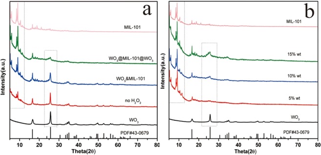
As shown in Fig. 2a, the crystal structure of MIL-101 is in good agreement with the literature reported41, demonstrating the formation of MIL-101 with ultrapure and good crystallinity. After loading WO3, the characteristic XRD peaks of MIL-101 in all samples are maintained, demonstrating the treatment did not have the damage on the crystal structure of MIL-101. The weaker peaks of WO3@MIL-101@WO3 than WO3&MIL-101 should be due to a part of WO3 have been embedded into pores of MIL-101 which resulted in small particle size. The patterns of different loading percentage were shown in Fig. 2b, as the loading percentage increased the intensity of the characteristic peaks increases. Different pH and concentration also show a significant influence on the intensity of MIL-101 shown in Fig. S1a,b.
Figure 2.
(a) XRD patterns of MIL-101, WO3@MIL-101@WO3, WO3&MIL-101, no hydrogen H2O2 and WO3. (b) The XRD patterns of samples with different loading percentage.
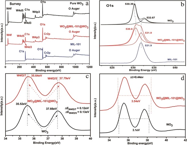
The survey pattern of WO3, WO3@MIL-101@WO3, and MIL-101 was shown in Fig. 3a.The high resolution XPS of O element (Fig. 3b) show the position 530.6 eV for WO3@MIL-101@WO3 which has right shift 0.21 eV compared with WO3, the absorbed oxygen at 532.67 eV was disappeared, indicating the O element has some changes in WO3@MIL-101@WO3 compared with pure WO3. Figure 3c,d show the binding energy shift and half band width changes, W4f2/7 and W4f2/5 have right shift 0.12 eV and 0.13 eV, respectively. The half band width of WO3@MIL-101@WO3 has been widen 0.44 eV compared with WO3, these results all show that W element has a good attachment with the linkages of MIL-101, there are interactions between WO3 and MIL-101.
Figure 3.
XPS. (a) The survey pattern of WO3, WO3@MIL-101@WO3, and MIL-101. (b) The shift and changed of O high resolution pattern of WO3, MIL-101, and WO3@MIL-101@WO3. (c) The shift of W element in WO3@MIL-101@WO3 and WO3, (d) The enlarged of half band width of W element in WO3@MIL-101@WO3 compared with WO3.
In order to further detect the relation of WO3 and MIL-101, DLS method was adapted. In Table S3, The zeta potential of WO3, WO3&MIL-101,WO3@MIL-101@WO3 and MIL-101 are −34.1 mV, −8.69 mV, −6.04 mV and 34.5 mV respectively. The result for WO3&MIL-101 (−8.69 mV) and WO3@MIL-101@WO3 (−6.04 mV) shows electrostatic attraction between MIL-101 and oppositely charged WO3. A close interaction of the WO3&MIL-101 and WO3@MIL-101@WO3 composite can be achieved with the electrostatic attraction. The more negative potential of WO3&MIL-101 than WO3@MIL-101@WO3 indicates there exist more WO3 nanoparticles on the surface of MIL-101.
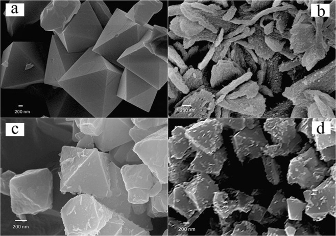
As shown in Fig. 4a, octahedral structure with smooth surface of MIL-101 have the size of 400 nm–600 nm27. As shown in Fig. 4b, the size of pure WO3 nanosheets are about 50 nm in thickness and 400 nm in width. After loading WO3, the surface of MIL-101 became rough and coating a slice WO3 on the surface of MIL-101 for WO3@MIL-101@WO3. For WO3&MIL-101, WO3 particles growth and there are intensity aggregating together with each other. The average particle size is about 40 nm shown as Fig. S2d. For the exploration experiment, we investigated the WO3@MIL-101@WO3 samples with different WO3 loading proportion (5–15%), different pH, different concentration and not adding hydrogen peroxide and the SEM results are displayed in Figs S2 and S3, and S4. As can be seen from Fig. S2, WO3 were thinly well coating on MIL-101 much like the morphology of WO3@MIL-101@WO3, as the loading proportion increasing, the amount of WO3 slice increase. Figure S2c show no hydrogen peroxide added in the solution, WO3 nanoparticles have grown much larger, indicating that the adding hydrogen peroxide can change the state of peroxo tungstate precursor gel, which is very important for WO3 embed into the pores of MIL-101. As can be seen Figs S3 and S4 in all WO3@MIL-101@WO3 samples, WO3 are all well slice coating outside MIL-101, with pH and concentration changes, the state of WO3 have some difference.
Figure 4.
SEM images of (a) MIL-101, (b) WO3, (c) (10%) WO3@MIL-101@WO3, (d) (10%) WO3&MIL-101.
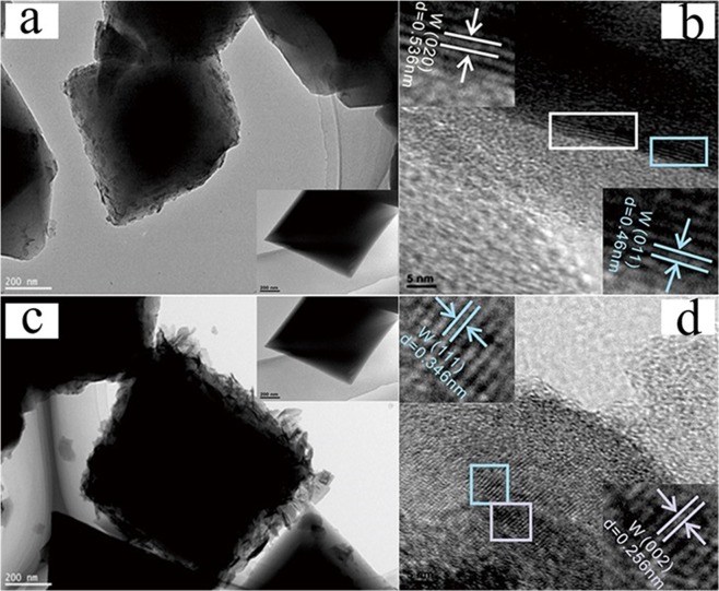
In order to study the morphology of MIL-101 (Fig. 5a,c insert), TEM and HRTEM measurements were carried27. The images of WO3@MIL-101@WO3 and WO3&MIL-101, MIL-101, WO3 were shown in Fig. 5. The insert picture shows a typical octahedral structure of MIL-101 which have an average size of 500 nm27. In the WO3@MIL-101@WO3 sample, WO3 was very little and well coating outside MIL-101, in WO3&MIL-101 sample, WO3 nanoparticles with a small size are well dispersed outside of MIL-101 without obvious aggregation, demonstrating that the MIL-101 can well hindering the growth of WO3 as an excellent matrix27. Displayed by the HRTEM images of WO3@MIL-101@WO3 and WO3&MIL-101, the marked lattice pitch of 0.536 nm and 0.46 nm on the surface of MIL-101 is corresponded to the (020) and (011) planes of WO3, and the marked lattice pitch of 0.346 nm and 0.256 nm on the shell is matched with the (111) and (002) planes of WO3. These results suggest that an intimate contact which will be helpful for the charge separation and transferring between WO3 and MIL-101. The energy dispersive X-ray spectroscopy (EDS) mapping (Fig. S5) was conducted to further confirmed the component and structure of WO3@MIL-101@WO3, the crystal structure of MIL-101 can be displayed by the uniform Cr elements in the background27.
Figure 5.
(a) TEM image of (10%) WO3@MIL-101@WO3 (insert was pure MIL-101), (b) HRTEM image of (10%) WO3@MIL-101@WO3 and the reflection of crystal face about its inverse FFT, (c) TEM image of (10%) WO3&MIL-101 (insert was pure MIL-101), (d) HRTEM image of (10%) WO3&MIL-101 and the reflection of crystal face about its inverse FFT.
To clarify the location of WO3 relative to MIL-101, the N2 adsorption measurement of MIL-101 was carried which shows type I property with secondary uptakes at p/p0 of around 0.1 and 0.2 (Fig. 6a), which is a typical MIL-101 adsorption curve50,51. After loading WO3 nanoparticles, the adsorption-desorption isotherm of WO3&MIL-101 sample has little changes but the adsorption-desorption isotherm of WO3@MIL-101@WO3 has a significant change compared with MIL-101 and WO3&MIL-101 and N2 adsorption decreased with the WO3 content increased. The surface area of MIL-101 was measured to be 2480 m2/g and the total pore size value was estimated to be 1.193 cm3/g at a relative pressure of 0.99 (shown in Table 1), both are similar to the numbers reported in the literature. The surface area of WO3&MIL-101 was 2350 m2/g and pore size value was 1.153 cm3/g, both are close to MIL-101. The surface area of WO3@MIL-101@WO3 samples gradually decreased from 1668 to 1255 m2/g, the pore size value change from 0.835 to 0.651 cm3/g, as WO3 content increased from 5% to 15%. The pore size distribution is shown in Fig. S7, the pore size at 1.8, 2.6 and 3.2 nm are attributed to pure MIL-101 which has been reported in literature50, compared with pure MIL-101, the pores size distribution of the WO3&MIL-101 have little changes while the pore size of WO3@MIL-101@WO3 have a significantly decrease than both pure MIL-101 and WO3&MIL-101. With the WO3 content increased, the pore size shows a decreasing trend. All these phenomena could be caused by WO3 embed into the pores of MIL-101. These results suggest that the WO3 nanoparticles in WO3@MIL-101@WO3 samples are successfully embedded in the cavities of MIL-101. WO3 nanoparticle has little influence for surface area and pore size of MIL-101, so WO3 nanoparticles are possibly on the surface of MIL-101 in WO3&MIL-101 sample.
Figure 6.
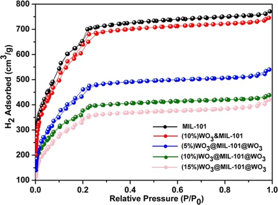
BET adsorption–desorption isotherm of MIL-101, (10%) WO3&MIL-101 and different loading percentage of WO3@MIL-101@WO3.
Table 1.
The surface area and pore size volume of MIL-101, (10%) WO3&MIL-101 and different loading percentage of WO3@MIL-101@WO3.
| Sample | BET Surface area (m2/g) | Pore size Volume (cm3/g) |
|---|---|---|
| MIL-101 | 2480 | 1.193 |
| (10%) WO3&MIL-101 | 2350 | 1.153 |
| (5%) WO3@MIL-101@WO3 | 1668 | 0.835 |
| (10%) WO3@MIL-101@WO3 | 1360 | 0.678 |
| (15%) WO3@MIL-101@WO3 | 1255 | 0.651 |
Combined with the TEM and SEM results, it can be concluded the WO3 particles just coat on the surface of MIL-101 in WO3&MIL-101 sample. The WO3 particles partly embed into the pores and partly on the surface of MIL-101 in WO3@MIL-101@WO3.
UV-Vis DRS analysis
UV-Vis DRS spectra were used to analyze the optical properties of the MIL-101 and the different WO3 loading proportion samples (Fig. 7). MIL-101 exhibits two characteristic absorption band centered at 450 nm and 600 nm, which coincides with that in literature27. The band of pure MIL-101 in the UV region belongs to π-π* transitions of ligands and the bands in the visible region can be assigned to the D-D spin-allowed transition of the Cr3+. WO3 displays a sharp fundamental absorption edge rise at 475 nm as expected, corresponding to a band gap of 2.75 eV7. Compared with that of MIL-101, the WO3@MIL-101@WO3 shows an enhanced board absorption in visible light region, this may correspond to the visible light enhanced of WO3. Compared with that of pure WO3, WO3@MIL-101@WO3 composite shows an adsorption band centered at 600 nm, which is attributed to the absorption of MIL-101 matrix.
Figure 7.

UV–vis DRS spectra of WO3, different loading percentage of WO3@MIL-101@WO3 and MIL-101.
Photocatalytic Degradation of Organic Pollutant
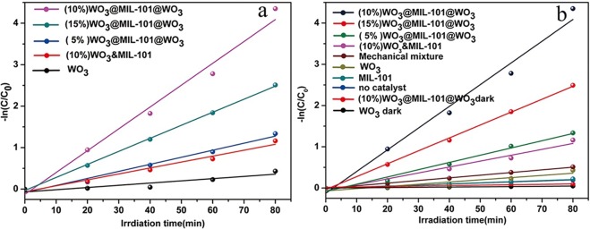
The MIL-101 loading WO3 samples were evaluated for photocatalytic MB degradation. As shown in Fig. 8a, comparing with pure WO3, the embedded structure WO3@MIL-101@WO3 and coating structure WO3&MIL-101 increased 9 times and 3 times, respectively, due to the closely contact between WO3 and MIL-101 which can be concluded from XPS and DLS data. Also, the embedded structure has 3 times higher efficiency than coating structure due to the part of WO3 have embeded into the pores of MIL-101 resulting in the shorter distance of the electrons transfer from WO3 to MIL-101 comparing with coating structure52. Figure 8b show the degradation efficiency of different loading percentages and a series of control experiment, which shown 10% WO3 loading sample has the best photocatalytic efficiency. From the control experiment, it can be seen that pure MIL-101 has no photocatalytic efficiency, MB cannot be degraded by self-sensitization and the light are the necessary condition during photocatalytic. Different pH and concentration were also investigated in Fig. S8a,b which shown that pH and concentration influence the photocatalytic efficiency of MB degradation. The WO3@MIL-101@WO3 has the best photocatalytic efficiency when the amount of HCl was 280 μL and the volume of water was 35 mL.
Figure 8.
(a) The reaction rate constants (k) of different loading percentage WO3@MIL-101@WO3, (10%)WO3&MIL-101 and WO3. (b) The reaction rate constants (k) of samples with different loading percentage and a series of control experiments.
Mechanism Investigation on Photocatalytic Performance Improvement
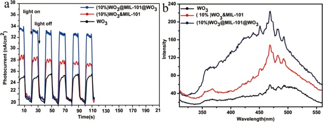
To further unveil the higher photocatalytic efficiency of WO3@MIL-101@WO3 than WO3&MIL-101, photocurrent measurement have been carried and the results show that the photocurrent for both MIL-101 supported WO3 get enhanced as compared to the pristine WO3 (Fig. 9a), revealing that the formation of WO3-MOF schottky junction helps to separate the photo-generated electron-hole pairs52. The WO3@MIL-101@WO3 displays much stronger photocurrent response than WO3&MIL-101, suggesting the much higher efficiency of the charge transfer52. This result is also supported by the photoluminescence (PL) emission spectroscopy, which provides useful hints for the photo-excited charge transfer and recombination. The PL intensity is slightly weakened when the WO3 only coating outside MOF, while get greatly suppressed when some WO3 nanoparticles have dispersed inside the MOF (Fig. 9b). These observations indicate that the irradiative electron-hole recombination is more effectively suppressed by extracting the electrons from internal WO3 than coating WO3 53. Such distinctly different photoelectron-chemical properties in WO3@MIL-101@WO3 and WO3&MIL-101 unambiguously demonstrate that the part of WO3 in the pores of MIL-101 contribute mostly of the photocatalytic efficiency of MB degradation. For comparison, we also investigated the photoluminescence (PL) emission spectroscopy of different WO3 loading percentage (Fig. S9), the PL intensity are corresponding with the photocatalytic efficiency. The WO3 loaded MOF samples all have lower intensity than pure WO3, pure MIL-101 have a lower photoluminescence emission. It indicated that WO3-MOF schottky junction can well suppressed the electron-hole pairs recombination and pure MIL-101 cannot be excited by visible light. In order to further investigate the migration and interface transfer or recombination rates of charge carriers electrochemical impedance spectra (EIS) was detected in Fig. S10. It was found that the WO3@MIL-101@WO3 and WO3&MIL-101 composite exhibits much smaller arc sizes than the pure WO3 under visible light irradiation. It demonstrates that the heterojunction composite has faster electron transfer through an intimated interface between MIL-101 and WO3 as compared to the pristine WO3, which is in good agreement with the photocatalytic performance.
Figure 9.
(a) Photocurrent responses of WO3, (10%) WO3&MIL-101 and (10%) WO3@MIL-101@WO3, (b) PL spectra of WO3, (10%) WO3&MIL-101 and (10%) WO3@MIL-101@WO3.
The photocatalytic mechanism of WO3@MIL-101@WO3 have been researched by active species trapping and ·OH quantify experiment during the photocatalytic process48. In order to study the active species of the photocatalytic reaction of WO3@MIL-101@WO3, the trapping experiment was investigated and showed in Fig. 10a. It can be concluded that the addition of AgNO3 (a quencher of e-, which can hinder the formation of O2−·) have no influence on photocatalytic degradation of MB48. On the contrary, the addition of IPA (a quencher of ·OH) or TEOA (a quencher of h+) have an obvious influence of decrease on the photocatalytic degradation of MB. Therefore, the conclusion can be drawn that photo-generated holes (h+) and ·OH are the main effective species on MB degradation for WO3@MIL-101@WO3 under visible light irradiation. The result consistent with the kind of effective species of pure WO3 and WO3&MIL-101. It can be concluded that the kind of active species have not changed after the combined. ·OH production quantification experiments have been revealed by the fluorescent intensity of TAOH for WO3, WO3&MIL-101 and WO3@MIL-101@WO3 in Fig. 10b. For WO3&MIL-101, the produce of ·OH just have little changed compared with pure WO3. But for WO3@MIL-101@WO3 the fluorescent intensity of TAOH compared with pure WO3 were totally different, there has a significant increase of ·OH. Above result can be explained: the electron produced from WO3 conduction band can be easily recombined due to the positive conduction level because of rapidly recombination of electron-hole pairs, so there are little ·OH produced for WO3. For WO3&MIL-101, because of the similar ·OH quantify result and the result of PL and photocurrent, the mechanism is the same as pure WO3. This can be explained that WO3 coating outside of MIL-101 only, nanoparticles are tending to be aggregating and electrons are favoring to be stacking and recombination rate increase. For WO3@MIL-101@WO3 the electrons produced from conduction band of WO3 transferred to MIL-101 due to the shorter electrons transfer distance. Due to the transformation of electrons, the holes can be separated to a greater degree, as a result, ·OH can be easily produced from high valence position of h+.
Figure 10.
(a) Trapping experiment of WO3@MIL-101@WO3 with IPA, AgNO3, TEOA and no quenching. (b) Transformation percentage of TA by WO3, WO3&MIL-101 and WO3@MIL-101@WO3.
This may also conclude that WO3 in the pores of MIL-101 have a shorter distance to transfer electrons from WO3 conduction band resulting in higher electrons-hole separation efficiency comparing with WO3&MIL-101, the same conclusion have been shown in the literature52. It may be the reason the embedded structure has higher efficiency than coating structure. The possible photocatalytic mechanism of WO3@MIL-101@WO3 and WO3&MIL-101 were shown in Figs 11 and 12.
Figure 11.
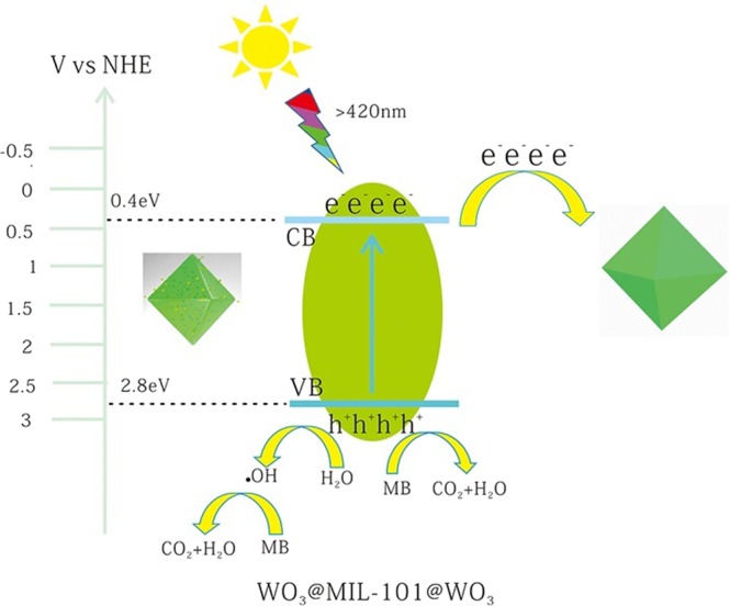
The possible photocatalytic mechanism scheme of WO3@MIL-101@WO3 under visible light irradiation (λ ≥ 420 nm).
Figure 12.

The possible photocatalytic mechanism scheme of WO3&MIL-101 under visible light irradiation (λ ≥ 420 nm).
Conclusion
The WO3@MIL-101@WO3 and WO3&MIL-101 hetero-structure were successfully synthesized, the WO3 nanoparticles were successfully embedded into the pores of MIL-101. MIL-101 can confine the particle size of WO3 and prevent the nanoparticles from aggregation and leaching to result in the enhancement of photo activity. Different loading percentage, pH and concentration were investigated to boost the photocatalytic degradation of MB, a great enhancement in photocatalytic activity is 10% content embedded structure sample, which increased 9 times activity compared with pure WO3 and 3 times compared with WO3&MIL-101. The photocatalytic mechanism of WO3@MIL-101@WO3 were investigated. Photocurrent, PL and ·OH, quantify experiment all show that when WO3 embedded into the pores of MIL-101, MIL-101 can play the role of promoting charge separation due to the short distance improving the electron-hole separation efficiency. The synthesis strategy presented here can be expended as a facile approach to synthesizing related dipping metal oxide into the pores of metal-organic framework for functional design and application.
Supplementary information
Supplementary Material of the manuscript
Acknowledgements
This work was supported by the National Natural Science Foundation of Jiangsu Province (BK20151248) and the Large-scale Instrument Equipment Sharing Foundation of Wuhan University. Analytical and Testing Center of Wuhan University. The authors also thank the Center for Electron Microscopy at Wuhan University.
Author Contributions
L.W. and L.Z. supervised the project. L.W. designed and carried out all experiments. L.Z. helped to revise the final format of the article.
Competing Interests
The authors declare no competing interests.
Footnotes
Publisher’s note: Springer Nature remains neutral with regard to jurisdictional claims in published maps and institutional affiliations.
Supplementary information
Supplementary information accompanies this paper at 10.1038/s41598-019-41374-z.
References
- 1.Luo X, et al. Facile One-Step Synthesis of Inorganic-Framework Molecularly Imprinted TiO2/WO3 Nanocomposite and Its Molecular Recognitive Photocatalytic Degradation of Target Contaminant. Environ. Sci. Technol. 2013;47:7404–7412. doi: 10.1021/es4013596. [DOI] [PubMed] [Google Scholar]
- 2.Seifollahi Bazarjani M, et al. Visible Light Photocatalysis with c-WO3 − x/WO3 × H2O Nanoheterostructures In Situ Formed in Mesoporous Polycarbosilane-Siloxane Polymer. J. Am. Chem. Soc. 2013;135:4467–4475. doi: 10.1021/ja3126678. [DOI] [PubMed] [Google Scholar]
- 3.Liu R, et al. Water Splitting by Tungsten Oxide Prepared by Atomic Layer Deposition and Decorated with an Oxygen‐Evolving Catalyst. Angew. Chem. Int. Ed. 2011;123:519–522. doi: 10.1002/ange.201004801. [DOI] [PubMed] [Google Scholar]
- 4.Grigioni I, Stamplecoskie KG, Selli E, Kamat PV. Dynamics of Photogenerated Charge Carriers in WO3/BiVO4 Heterojunction Photoanodes. J. Phys. Chem. C. 2015;119:20792–20800. doi: 10.1021/acs.jpcc.5b05128. [DOI] [Google Scholar]
- 5.Bi D, Xu Y. Improved Photocatalytic Activity of WO3 through Clustered Fe2O3 for Organic Degradation in the Presence of H2O2. Langmuir. 2011;27:9359–9366. doi: 10.1021/la2012793. [DOI] [PubMed] [Google Scholar]
- 6.Luan, J., Shen, Y., Li, Y. & Paz, Y. The Structural, Photocatalytic Property Characterization and Enhanced Photocatalytic Activities of Novel Photocatalysts Bi2GaSbO7 and Bi2InSbO7 during Visible Light Irradiation. Materials9 (2016). [DOI] [PMC free article] [PubMed]
- 7.Wenderich K, Klaassen A, Siretanu I, Mugele F, Mul G. Sorption‐Determined Deposition of Platinum on Well‐Defined Platelike WO3. Angew. Chem. Int. Ed. 2014;53:12476–12479. doi: 10.1002/anie.201405274. [DOI] [PubMed] [Google Scholar]
- 8.Pesci FM, Cowan AJ, Alexander BD, Durrant JR, Klug DR. Charge Carrier Dynamics on Mesoporous WO3 during Water Splitting. J. Phys. Chem. Lett. 2011;2:1900–1903. doi: 10.1021/jz200839n. [DOI] [Google Scholar]
- 9.Arutanti O, Nandiyanto ABD, Ogi T, Kim TO, Okuyama K. Influences of Porous Structurization and Pt Addition on the Improvement of Photocatalytic Performance of WO3 Particles. ACS Appl. Mater. Interfaces. 2015;7:3009–3017. doi: 10.1021/am507935j. [DOI] [PubMed] [Google Scholar]
- 10.Jeon D, Kim N, Bae S, Han Y, Ryu J. WO3/Conducting Polymer Heterojunction Photoanodes for Efficient and Stable Photoelectrochemical Water Splitting. ACS Appl. Mater. Interfaces. 2018;10:8036–8044. doi: 10.1021/acsami.7b19203. [DOI] [PubMed] [Google Scholar]
- 11.Li Y, Tang Z, Zhang J, Zhang Z. Defect Engineering of Air-Treated WO3 and Its Enhanced Visible-Light-Driven Photocatalytic and Electrochemical Performance. J. Phys. Chem. C. 2016;120:9750–9763. doi: 10.1021/acs.jpcc.6b00457. [DOI] [Google Scholar]
- 12.Kim J, Lee CW, Choi W. Platinized WO3 as an Environmental Photocatalyst that Generates OH Radicals under Visible Light. Environ. Sci. Technol. 2010;44:6849–6854. doi: 10.1021/es101981r. [DOI] [PubMed] [Google Scholar]
- 13.Xi G, et al. Ultrathin W18O49 Nanowires with Diameters below 1 nm: Synthesis, Near‐Infrared Absorption, Photoluminescence, and Photochemical Reduction of Carbon Dioxide. Angew. Chem. Int. Ed. 2012;51:2395–2399. doi: 10.1002/anie.201107681. [DOI] [PubMed] [Google Scholar]
- 14.Xi G, et al. In Situ Growth of Metal Particles on 3D Urchin-Like WO3 Nanostructures. J. Am. Chem. Soc. 2012;134:6508–6511. doi: 10.1021/ja211638e. [DOI] [PubMed] [Google Scholar]
- 15.Zhao ZG, Miyauchi M. Nanoporous‐Walled Tungsten Oxide Nanotubes as Highly Active Visible‐Light‐Driven Photocatalysts. Angew. Chem. Int. Ed. 2008;47:7051–7055. doi: 10.1002/anie.200802207. [DOI] [PubMed] [Google Scholar]
- 16.Ma B, Guo J, Dai W-L, Fan K. Ag-AgCl/WO3 Hollow Sphere with Flower-Like Structure and Superior Visible Photocatalytic Activity. Appl. Catal. B. 2012;123–124:193–199. doi: 10.1016/j.apcatb.2012.04.029. [DOI] [Google Scholar]
- 17.Ding J, et al. Selective Deposition of Silver Nanoparticles onto WO3 Nanorods with Different Facets: The Correlation of Facet-Induced Electron Transport Preference and Photocatalytic Activity. J. Phys. Chem. C. 2016;120:4345–4353. doi: 10.1021/acs.jpcc.5b10580. [DOI] [Google Scholar]
- 18.Bu Y, Chen Z, Sun C. Highly Efficient Z-Scheme Ag3PO4/Ag/WO3−x Photocatalyst for Its Enhanced Photocatalytic Performance. Appl. Catal. B. 2015;179:363–371. doi: 10.1016/j.apcatb.2015.05.045. [DOI] [Google Scholar]
- 19.Xiang Q, et al. Au Nanoparticle Modified WO3 Nanorods with Their Enhanced Properties for Photocatalysis and Gas Sensing. J. Phys. Chem. C. 2010;114:2049–2055. doi: 10.1021/jp909742d. [DOI] [Google Scholar]
- 20.Zhang Q, et al. Light-Driven Au-WO3@C Janus Micromotors for Rapid Photodegradation of Dye Pollutants. ACS Appl. Mater. Interfaces. 2017;9:4674–4683. doi: 10.1021/acsami.6b12081. [DOI] [PubMed] [Google Scholar]
- 21.Tomita O, Otsubo T, Higashi M, Ohtani B, Abe R. Partial Oxidation of Alcohols on Visible-Light-Responsive WO3 Photocatalysts Loaded with Palladium Oxide Cocatalyst. ACS Catal. 2016;6:1134–1144. doi: 10.1021/acscatal.5b01850. [DOI] [Google Scholar]
- 22.Yu X, Cohen SM. Photocatalytic Metal–Organic Frameworks for Selective 2,2,2-Trifluoroethylation of Styrenes. J. Am. Chem. Soc. 2016;138:12320–12323. doi: 10.1021/jacs.6b06859. [DOI] [PubMed] [Google Scholar]
- 23.Zhang Z-M, et al. Photosensitizing Metal–Organic Framework Enabling Visible-Light-Driven Proton Reduction by a Wells–Dawson-Type Polyoxometalate. J. Am. Chem. Soc. 2015;137:3197–3200. doi: 10.1021/jacs.5b00075. [DOI] [PubMed] [Google Scholar]
- 24.Xu H-Q, et al. Visible-Light Photoreduction of CO2 in a Metal–Organic Framework: Boosting Electron–Hole Separation via Electron Trap States. J. Am. Chem. Soc. 2015;137:13440–13443. doi: 10.1021/jacs.5b08773. [DOI] [PubMed] [Google Scholar]
- 25.Wang, R., Dong, X. Y., Du, J., Zhao, J. Y. & Zang, S. Q. MOF‐Derived Bifunctional Cu3P Nanoparticles Coated by a N,P‐Codoped Carbon Shell for Hydrogen Evolution and Oxygen Reduction. Adv. Mater. 30 (2018). [DOI] [PubMed]
- 26.Wu ZL, et al. A Semi‐Conductive Copper–Organic Framework with Two Types of Photocatalytic Activity. Angew. Chem. Int. Ed. 2016;55:4938–4942. doi: 10.1002/anie.201508325. [DOI] [PubMed] [Google Scholar]
- 27.Wang Y, et al. Controlled Fabrication and Enhanced Visible-Light Photocatalytic Hydrogen Production of Au@CdS/MIL-101 Heterostructure. Appl. Catal. B. 2016;185:307–314. doi: 10.1016/j.apcatb.2015.12.020. [DOI] [Google Scholar]
- 28.Guan BY, Yu XY, Wu HB, Lou XW. Complex Nanostructures from Materials Based on Metal–Organic Frameworks for Electrochemical Energy Storage and Conversion. Adv. Mater. 2017;29:47. doi: 10.1002/adma.201703614. [DOI] [PubMed] [Google Scholar]
- 29.Kim D, Whang DR, Park SY. Self-Healing of Molecular Catalyst and Photosensitizer on Metal–Organic Framework: Robust Molecular System for Photocatalytic H2 Evolution from Water. J. Am. Chem. Soc. 2016;138:8698–8701. doi: 10.1021/jacs.6b04552. [DOI] [PubMed] [Google Scholar]
- 30.Gu Y, et al. Controllable Modular Growth of Hierarchical MOF‐on‐MOF Architectures. Angew. Chem. Int. Ed. 2017;56:15658–15662. doi: 10.1002/anie.201709738. [DOI] [PubMed] [Google Scholar]
- 31.Liang, Z., Qu, C., Xia, D., Zou, R. & Xu, Q. Atomically Dispersed Metal Sites in MOF‐Based Materials for Electrocatalytic and Photocatalytic Energy Conversion. Angew. Chem. Int. Ed (2018). [DOI] [PubMed]
- 32.Liu H, Xu C, Li D, Jiang HL. Photocatalytic Hydrogen Production Coupled with Selective Benzylamine Oxidation over MOF Composites. Angew. Chem. Int. Ed. 2018;130:5477–5481. doi: 10.1002/ange.201800320. [DOI] [PubMed] [Google Scholar]
- 33.Ryu U, et al. Nanocrystalline Titanium Metal–Organic Frameworks for Highly Efficient and Flexible Perovskite Solar Cells. ACS Nano. 2018;12:4968–4975. doi: 10.1021/acsnano.8b02079. [DOI] [PubMed] [Google Scholar]
- 34.Zhang X, Zhang X, Johnson JA, Chen Y-S, Zhang J. Highly Porous Zirconium Metal–Organic Frameworks with β-UH3-like Topology Based on Elongated Tetrahedral Linkers. J. Am. Chem. Soc. 2016;138:8380–8383. doi: 10.1021/jacs.6b04608. [DOI] [PubMed] [Google Scholar]
- 35.Leng F, Liu H, Ding M, Lin Q-P, Jiang H-L. Boosting Photocatalytic Hydrogen Production of Porphyrinic MOFs: The Metal Location in Metalloporphyrin Matters. ACS Catal. 2018;8:4583–4590. doi: 10.1021/acscatal.8b00764. [DOI] [Google Scholar]
- 36.Wu P, et al. Photoactive Chiral Metal–Organic Frameworks for Light-Driven Asymmetric α-Alkylation of Aldehydes. J. Am. Chem. Soc. 2012;134:14991–14999. doi: 10.1021/ja305367j. [DOI] [PubMed] [Google Scholar]
- 37.Wang Y, et al. Hydroxide Ligands Cooperate with Catalytic Centers in Metal–Organic Frameworks for Efficient Photocatalytic CO2 Reduction. J. Am. Chem. Soc. 2018;140:38–41. doi: 10.1021/jacs.7b10107. [DOI] [PubMed] [Google Scholar]
- 38.Liu Y, Tang Z. Multifunctional Nanoparticle@MOF Core–Shell Nanostructures. Adv. Mater. 2013;25:5819–5825. doi: 10.1002/adma.201302781. [DOI] [PubMed] [Google Scholar]
- 39.Nguyen HL, et al. A Titanium–Organic Framework as an Exemplar of Combining the Chemistry of Metal– and Covalent–Organic Frameworks. J. Am. Chem. Soc. 2016;138:4330–4333. doi: 10.1021/jacs.6b01233. [DOI] [PubMed] [Google Scholar]
- 40.Wang C, deKrafft KE, Lin W. Pt Nanoparticles@Photoactive Metal–Organic Frameworks: Efficient Hydrogen Evolution via Synergistic Photoexcitation and Electron Injection. J. Am. Chem. Soc. 2012;134:7211–7214. doi: 10.1021/ja300539p. [DOI] [PubMed] [Google Scholar]
- 41.Han J, et al. Metal-Organic Framework Immobilized Cobalt Oxide Nanoparticles for Efficient Photocatalytic Water Oxidation. J. Mater. Chem. A. 2015;3:20607–20613. doi: 10.1039/C5TA04675K. [DOI] [Google Scholar]
- 42.Li H, et al. Palladium Nanoparticles Confined in the Cages of MIL-101: An Efficient Catalyst for the One-Pot Indole Synthesis in Water. ACS Catal. 2011;1:1604–1612. doi: 10.1021/cs200351p. [DOI] [Google Scholar]
- 43.Aijaz A, et al. Immobilizing Highly Catalytically Active Pt Nanoparticles Inside the Pores of Metal–Organic Framework: A Double Solvents Approach. J. Am. Chem. Soc. 2012;134:13926–13929. doi: 10.1021/ja3043905. [DOI] [PubMed] [Google Scholar]
- 44.Tian L, Ye L, Deng K, Zan L. TiO2/Carbon Nanotube Hybrid Nanostructures: Solvothermal Synthesis and Their Visible Light Photocatalytic Activity. J. Solid State Chem. 2011;184:1465–1471. doi: 10.1016/j.jssc.2011.04.014. [DOI] [Google Scholar]
- 45.Ye L, et al. Two Different Roles of Metallic Ag on Ag/AgX/BiOX (X = Cl, Br) Visible Light Photocatalysts: Surface Plasmon Resonance and Z-Scheme Bridge. ACS Catal. 2012;2:1677–1683. doi: 10.1021/cs300213m. [DOI] [Google Scholar]
- 46.Hao Q, et al. One-Pot Synthesis of C/Bi/Bi2O3 Composite with Enhanced Photocatalytic Activity. Appl. Catal. B. 2017;219:63–72. doi: 10.1016/j.apcatb.2017.07.030. [DOI] [Google Scholar]
- 47.Li W, et al. Evidence for the Active Species Involved in the Photodegradation Process of Methyl Orange on TiO2. J. Phys. Chem. C. 2012;116:3552–3560. doi: 10.1021/jp209661d. [DOI] [Google Scholar]
- 48.Ye L, Liu J, Jiang Z, Peng T, Zan L. Facets Coupling of BiOBr-g-C3N4 Composite Photocatalyst for Enhanced Visible-Light-Driven Photocatalytic Activity. Appl. Catal. B. 2013;142–143:1–7. [Google Scholar]
- 49.Ye L, Liu J, Jiang Z, Peng T, Zan L. The Pure Shape Effect with A Removing Facet Effect of Single-Crystalline Anatase TiO2 (101) for Photocatalytic Application. Nanoscale. 2013;5:9391–9396. doi: 10.1039/c3nr02273k. [DOI] [PubMed] [Google Scholar]
- 50.Rallapalli PBS, et al. Activated Carbon @ MIL‐101(Cr): A Potential Metal‐Organic Framework Composite Material for Hydrogen Storage. Int. J. Energy Res. 2013;37:746–753. doi: 10.1002/er.1933. [DOI] [Google Scholar]
- 51.Férey G, et al. A Chromium Terephthalate-Based Solid with Unusually Large Pore Volumes and Surface Area. Science. 2005;309:2040. doi: 10.1126/science.1116275. [DOI] [PubMed] [Google Scholar]
- 52.Xiao JD, et al. Boosting Photocatalytic Hydrogen Production of a Metal–Organic Framework Decorated with Platinum Nanoparticles: The Platinum Location Matters. Angew. Chem. Int. Ed. 2016;55:9389–9393. doi: 10.1002/anie.201603990. [DOI] [PubMed] [Google Scholar]
- 53.Liu L, et al. Exceptionally Robust In-Based Metal–Organic Framework for Highly Efficient Carbon Dioxide Capture and Conversion. Inorg. Chem. 2016;55:3558–3565. doi: 10.1021/acs.inorgchem.6b00050. [DOI] [PubMed] [Google Scholar]
Associated Data
This section collects any data citations, data availability statements, or supplementary materials included in this article.
Supplementary Materials
Supplementary Material of the manuscript


