Abstract
The synthesis of new C60 fullerene derivatives functionalized with thiophene moieties as well as with electron donating or electron withdrawing groups, bromine (Br) or cyano (CN), respectively, using Bingel reactions is reported. The synthesized derivatives were used as the electron transporting materials (ETMs) in inverted perovskite solar cells (PSCs). Compared to devices fabricated with [6,6]-phenyl-C61-butyric acid methyl ester (PC61BM), the new derivatives showed similar electrochemical properties and electron mobilities. However, PSCs based on the new derivatives synthesized in this work exhibited higher power conversion efficiencies (PCEs) than PC61BM based devices, which were ascribed to their better passivation ability, likely due to specific interactions between the fullerene addend and the perovskite layer surface. Devices based on the fullerene bearing the CN group exhibited an additionally improved efficiency due to the increased dielectric constant (εr) of this derivative. These results show that the new functionalized fullerene derivatives can act as efficient ETMs in inverted PSCs.
Keywords: fullerene derivatives, thiophene, Bingel adducts, electron transporting materials, perovskite solar cells
TOC
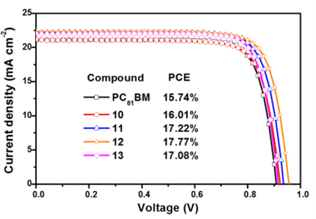
Devices based on the new fullerene derivatives exhibited an improved overall performance compared to those with PC61BM as the electron transporting material.
Introduction
In the past few years the development of organic-inorganic hybrid PSCs has progressed quickly not only because of their increasing PCE values (certified values up to 22.7%)1 but also because of their multiple applications.2–5 To find more viable and efficient PSC device-configurations, the inverted structures are very promising due to their easy fabrication6, 7 and relatively high PCEs (21.0%, highest certified value),8 among other reasons. Inverted structures are typically fabricated using a transparent indium tin oxide electrode or fluorinated tin oxide (ITO or FTO, respectively),9, 10 a hole transporting layer (HTL) of poly(3,4-ethylenedioxythiophene)-poly(styrenesulfonate) (PEDOT:PSS),11 nickel oxide (NiOx)12 or poly[bis(4-phenyl)(2,4,6-trimethylphenyl)amine] (PTAA),8 followed by the perovskite layer,6 the electron transporting layer (ETL, mainly fullerenes),6 and the back metal electrode (Al or Ag).13, 14 The ETL not only extracts and transports the electrons from the perovskite layer to the back electrode, it also avoids water intrusion from the environment to the perovskite layer, thus retarding perovskite degradation.13 In this regard, the relatively good electron mobility, solution processability, and HOMO/LUMO levels that match with those of the perovskite make fullerenes highly promising ETMs in inverted PSCs.6, 15–17
Besides PC61BM, several fullerene derivatives have been used as the ETMs in PSCs.6 In a first attempt to understand the role of the fullerenes’ addend on PSCs, we studied the effect of amino and carboxylic groups on both C60 and C70 fullerene cages (dimethoxy carbonyl pyrrolidine C60/70 DMEC60 and DMEC70, respectively), where some specific interactions between the perovskite and the amino and carboxyl groups were observed using FTIR,10 which yielded improved device performances and long-term device stabilities, compared to PC61BM-based devices.
One limitation of the PSCs is that the perovskite crystals contain uncoordinated ions at the crystal surface and at the grain boundaries,18 which are electron trap sites that give rise to charge recombination and hysteretic behavior.19 Passivation of these trap sites has become crucial to fabricate high performing PSCs. Noel et al. reported that organic Lewis bases such as thiophene and pyridine can passivate the crystal surfaces of the perovskite by coordination between the sulfur atom of the thiophene or the nitrogen atom of the pyridine with under-coordinated Pb+2 (Lewis acid) in the perovskite, resulting in PCE improvements up to 27%.18 It has also been reported that fullerenes can passivate these trap states at the surface as well as at the grain boundaries, being extensively used to reduce/eliminate hysteretic behavior for both regular and inverted PSC configurations.6, 15–17 By using time-resolved (TR) and steady state photoluminescence (PL), combined with impedance spectroscopy measurements, Shao et al. reported that trap-assisted recombination at the perovskite/fullerene interface is effectively suppressed when using a fullerene derivative with a higher εr.20 The most common approaches to increase the εr on fullerenes is by introducing highly polar groups such as CN21 or triethyleneglycol (TEG).22
Considering the above-mentioned characteristics, and without sacrificing optical, electronic and solubility properties, here we report the synthesis of new C60 fullerene derivatives that contain thiophene- (Lewis base) and either a CN group (to increase εr) or Br, and their application as efficient ETMs in inverted PSCs. In all cases, PSCs based on the new fullerene derivatives exhibited improved overall performance and long-term device stability than those based on PC61BM.
Materials Synthesis
Experimental
All chemicals were reagent grade. Silica gel (40–60 µ, 60 Å) was used to separate and purify the products. Matrix-assisted laser desorption/ionization time-of-flight mass spectroscopy (MALDI-TOF-MS) was conducted on positive mode, with samples dissolved in carbon disulfide and 1,1,4,4-tetraphenyl-1,3-butadiene (TPB) as matrix. NMR spectra were recorded using a Bruker 400 MHz spectrometer. The UV/Vis-NIR spectra were recorded for chloroform solutions. Cyclic voltammetry (CV) experiments were carried out under an argon atmosphere at room temperature. The scan rate for the CV experiments was 100 mV/s. A one compartment cell with a standard three-electrode set up was used, consisting of a 1 mm diameter glassy carbon disk as the working electrode, a platinum wire as the counter electrode and a silver wire as a pseudo-reference electrode, in a solution of anhydrous o-DCB containing 0.05 M n-Bu4NPF6. Ferrocene was added to the solution at the end of each experiment as an internal standard.
Synthesis of compound 6:
Compound 1 (640 mg, 5 mmol) and compound 2 (755 mg, 5 mmol) were dissolved in dry THF (30 mL) and stirred for 5 min at room temperature. Triethylamine (TEA) (1 mL, 7.2 mmol) was added dropwise to the solution and the reaction mixture was stirred for 5 h at room temperature. The solvent was dried under vacuum and the crude product was purified by silica gel column chromatography using a mixture of hexanes:ethyl acetate (4:1 ratio). Compound 6 was obtained as a colorless oil; yield 85%.
Synthesis of compound 7:
Compound 7 was synthesized following the same procedure as that used for the synthesis of compound 6. The crude product was purified by silica gel column chromatography using a mixture of hexanes:ethyl acetate (9:1 ratio). Compound 7 was obtained as a colorless oil; yield 89%.
Synthesis of compound 8:
To 805 mg (5 mmol) of compound 4 dissolved in dry dichloromethane (50 mL), 1545 mg (7.5 mmol) of dicyclohexylcarbodiimide (DCC) were added at room temperature. The reaction was stirred for 10 min and 2483 mg (7.5 mmol) of 4-dimethylaminopyridine (DMAP) were added and the reaction was stirred for 10 min. 640 mg (5 mmol) of compound 1 were added and the reaction was stirred overnight at room temperature. The mixture was filtered to remove the solid. The solvent was removed under vacuum and the crude was purified by silica gel column chromatography using a mixture of hexanes:ethyl acetate (4:1 ratio). Compound 8 was obtained as a white solid; yield 93%.
Synthesis of compound 9:
Compound 9 was synthesized following the same procedure than that used for the synthesis of compound 8. The crude product was purified by silica gel column chromatography using a mixture of hexanes:ethyl acetate (9:1 ratio). Compound 9 was obtained as a colorless oil; yield 84%.
Synthesis of compound 10:
C60 (72 mg, 0.1 mmol) was dissolved in o-DCB (15 mL) and compound 6 (30 mg, 0.12 mmol) and tetrabromomethane (CBr4) (75 mg, 0.22 mmol) were added and stirred at room temperature for 2 min. 1,8-Diazabicyclo[5.4.0]undec-7-ene (DBU) (16 mg, 0.1 mmol) was added and the reaction was stirred for 10 minutes. After the addition of the DBU the reaction was monitored by thin layer chromatography (TLC) using CS2 to check the unreacted C60 and a mixture of CS2:CHCl3 (4:1 ratio) to track the formation of the monoadduct derivative. The solution was directly poured onto a silica gel column and CS2 was used to separate the non-reacted C60. Compound 10 was purified using a CS2:CHCl3 (4:1) mixture, yield 59%.
Synthesis of compound 11:
Compound 11 was synthesized following the same procedure as that used for the synthesis of compound 10. Compound 11 was purified using a CS2:CHCl3 (4:1) mixture; yield 55%.
Synthesis of compound 12:
Compound 12 was synthesized following the same procedure as that used for the synthesis of compound 10. Compound 12 was purified using toluene; yield 56%.
Synthesis of compound 13:
Compound 13 was synthesized following the same procedure as that used for the synthesis of compound 10. Compound 13 was purified using CS2:CHCl3 (9:1) mixture; yield 54%.
Device Fabrication
PC61BM (99%) was bought from SES Research. Methylammonium iodide (CH3NH3I, 99.5%) was bought from Greatcellsolar. PbI2 (99%) was bought from Sigma-Aldrich. The configuration used for the fabrication of the PSCs was ITO/PEDOT:PSS/CH3NH3PbI3/ETM/Al. The patterned ITO glass substrates were cleaned sequentially with detergent, deionized water and acetone, each step for 30 min, then dried with nitrogen gas and finally treated in a UV-ozone oven for 30 min. After passing through a 0.45 μm PVDF filter, the PEDOT:PSS solution (Baytron P VP AI 4083) was spin-coated onto the treated ITO substrates at 5000 rpm for 30 s and heated at 150 °C for 15 min in air. Then the substrates were transferred to a N2-filled glovebox where CH3NH3PbI3 (1 M solution in DMF) was spin-coated on top of the PEDOT:PSS coated substrates at 800 rpm for 10 s and at 4000 rpm for 25 s. 80 µL of toluene were added 5 s after the second step and then the devices were annealed at 70 °C for 60 min (a pure perovskite film was observed by XRD characterization, Figure S20). The fullerene derivatives dissolved in chlorobenzene (20 mg/mL) were spin-coated onto the CH3NH3PbI3 layer at 5000 rpm for 30 s. Finally, Al electrodes (100 nm) were deposited by thermal evaporation under a pressure of 1×10⁻⁶ Torr through a shadow mask. The active area of the fabricated devices was 6 mm2. The Al electrodes were encapsulated with a UV-curable epoxy resin and a glass slide before testing. Stability studies were conducted on unencapsulated devices.
Results and discussion
The thiophene-based C60 fullerene derivatives 10–13 were synthesized as illustrated in scheme 1. Thiophene groups were selected not only to induce solubility, but also for their ability to passivate the perovskite crystals through sulfur-under-coordinated Pb+2 interactions (S···Pb), as theoretically and experimentally reported.18, 23, 24 Considering that the CN group can increase the εr of fullerenes (from ~3 up to ~5)21 it was introduced with the aim to polarize and increase the εr of the thiophene-based fullerenes. Finally, compounds 10–13 were synthesized via Bingel reactions that yield only [6,6]-isomers at room temperature, in good yields, and in short reaction times (see experimental section for details), compared to the synthesis of the widely used PC61BM via the tosylhydrazone route developed by Hummelen et al., which leads to a mixture of isomers resulting from [5,6]-opened and [6,6]-closed additions, low yields, and long reaction times.25
Scheme 1.
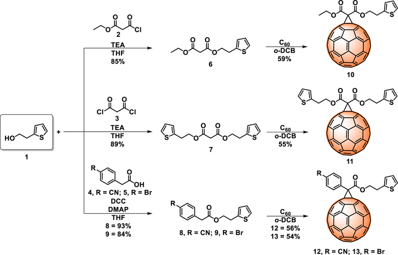
Synthesis of the thiophene-based C60 fullerene derivatives 10–13.
The chemical structures of compounds 6–13 were confirmed by MALDI-TOF-MS, 1H- and 13C-NMR spectroscopy and UV-vis absorption (see supporting information, Figures S1-S12).
The electrochemical properties of compounds 10–13 were measured by CV on a glassy carbon electrode with o-DCB as the solvent and n-Bu4NPF6 as the supporting electrolyte. The onset of the first reduction potentials are shown in table 1. Very similar reduction potentials were observed for compounds 10–13 and PC61BM,26 as well as at least two well-defined and quasireversible redox waves (Figure S13). The LUMO energy levels of compounds 10–13 were calculated from their onset reduction potentials () using the formula: (eV).27 The LUMO levels of compounds 10–13 are all estimated to be −3.88, −3.88, −3.88 and −3.86 eV, respectively. The HOMO energy levels of compounds 10–13 were calculated from their UV-absorption onset (Eg) (Figure S14) using the formula: HOMO = −e (LUMO − Eg) (eV). These results show that the LUMO/HOMO levels of compounds 10–13 are not affected by the presence of thiophene, CN or Br groups (Table 1).
Table 1.
Optical bandgap, onset reduction and LUMO/HOMO energy levels of PC61BM and 10–13.
| Compound | λabs (nm) | Eg (eV) | (V) | LUMO (eV) | HOMO (eV) |
|---|---|---|---|---|---|
| PC61BM* | 718 | 1.73 | 0.90 | ‒3.90 | ‒5.63 |
| 10 | 709 | 1.75 | 0.92 | ‒3.88 | ‒5.63 |
| 11 | 712 | 1.74 | 0.92 | ‒3.88 | ‒5.62 |
| 12 | 707 | 1.75 | 0.92 | ‒3.88 | ‒5.63 |
| 13 | 711 | 1.74 | 0.94 | ‒3.86 | ‒5.60 |
LUMO/HOMO values were taken from the literature.26
The εr of the ETM plays an important role in preventing electron-hole recombinations in PSCs.20, 28 It has been proven that εr is inversely proportional to the recombination ratio (rc), as shown in equation 1.20
| (1) |
where q, T, ε0 and er are the elementary charge, temperature, vacuum permittivity and the dielectric constant of the ETM, respectively.
Electrochemical impedance (EIS) was performed to measure the εr of the fullerene derivatives 10–13 and PC61BM. The dependence of εr of 10–13 vs frequency (10 Hz - 0.1 MHz) is shown in figure 1a. Compounds 10, 11 and 13 exhibit similar εr than that of PC61BM (around 3.9), but compound 12, due to the presence of the CN group, exhibits a larger dipole moment than those of compounds 10, 11, 13 and PC61BM (Table 2). It is known that fullerenes functionalized with CN groups exhibit increased εr values by up to 26%.21
Figure 1.
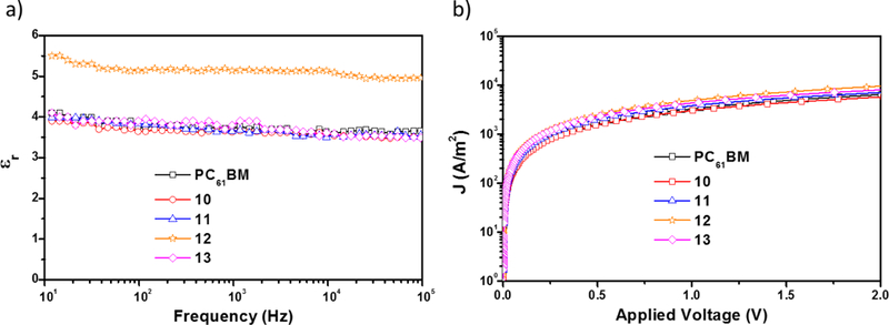
a) dielectric constant vs frequency and b) electron mobility of the fullerene derivatives 10–13 and PC61BM.
Table 2.
Dielectric constant and electron mobility of the fullerene derivatives 10–13 and PC61BM.
| Compound | εr | μe (cm2 V‒1 s‒1) |
|---|---|---|
| PC61BM | 3.8 ± 3 | 3.34×10‒4 |
| 10 | 3.6 ± 3 | 1.32×10‒4 |
| 11 | 3.7 ± 3 | 4.58×10‒4 |
| 12 | 5.2 ± 3 | 7.68×10‒4 |
| 13 | 3.7 ± 3 | 6.21×10‒4 |
The electron mobility (μe) of fullerenes is also a very important parameter for their application as ETMs in PSCs.15 The μe values of all fullerenes were measured using the space charge limit current (SCLC) method,29 and using the dark J-V curves of electron-only devices with the configuration of ITO/Al/ETM/Al (Figure 1b). As listed in table 2, the μe of compounds 10–13 and PC61BM were determined to be 1.32×10⁻⁴, 4.58×10⁻⁴, 7.68×10⁻⁴, 6.21×10⁻⁴ and 3.34×10⁻⁴ cm2 V−1 s−1, respectively. These results show that the μe values of compounds 10–13 were not considerable affected by the presence of the thiophene, CN or Br groups.
The ability of compounds 10–13 to work as ETMs was tested by fabricating PSCs as schematically represented in figure 2a and described in detail in the experimental section. Figure 2b and 2c are top- and cross section SEM images of the perovskite film and PSC, respectively. The top-view image (Figure 2b) shows a homogeneous perovskite layer with large crystalline grains (~400 nm) and without apparent pinholes. Figure 2c shows the cross-section image of the PSC, where the perovskite layer adjacent to the HTL and ETL is clearly distinguished. Device performance variations are the result of the different fullerene derivative layers since all the PSCs were fabricated under identical conditions.
Figure 2.

(a) representation of the PSCs, (b) top-view SEM image of the perovskite film, and (c) cross-section SEM image of the device (ITO/PEDOT:PSS/perovskite/fullerene).
Figure 3b shows the J-V curves of the PSCs fabricated using compounds 10–13 and PC61BM as the ETMs. The control device based on PC61BM showed a performance with a Jsc of 21.10 mA/cm2, a Voc of 0.91 V, a fill factor (FF) of 0.82%, and a PCE of 15.11±0.6%. In contrast, devices based on compounds 10–13 showed significantly improved overall performances with average PCEs of 15.51±0.5%, 16.61±0.6%, 17.36±0.4% and 16.35±0.7%, respectively. The higher performance obtained from devices based on 12 (Jsc = 22.30, Voc = 0.96, FF = 0.83% and PCE = 17.77%) results from the synergistic combination of specific surface interactions and higher εr value, which inhibit charge recombination and enhance charge collection.15, 20, 30 The main photovoltaic characteristics are summarized in table 3. PSCs based on the fullerene derivatives showed negligible hysteretic behavior (Figures S15a-e). Device performance reproducibilities are calculated from the PCE distributions measured for 48 independent cells (Figure 3c). From figure 3d, it is clear that the EQE of the PSCs based on 12 are noticeably higher across the entire photoresponse range. The integrated photocurrent densities based on EQE measurements (Figure 3d) are consistent with those from J-V measurements (Table 3). The improved device performance was attributed to the better passivation ability of compounds 10–13, because of specific interactions between the functional groups from the fullerene and the perovskite layer. Figure 4 shows the Fourier transform infrared (FTIR) spectra of the perovskite, compound 12 and perovskite/12 films. Clearly for the perovskite/12 film the stretching bands at 2228 cm−1 (CN) and 1735 cm−1 (CO) are shifted and decreased in intensity, indicating the interaction between the fullerene and the perovskite layer, a similar trend was observed for the CO stretching band of compounds 10, 11, 13 and PC61BM (Figures S16-S18).
Figure 3.
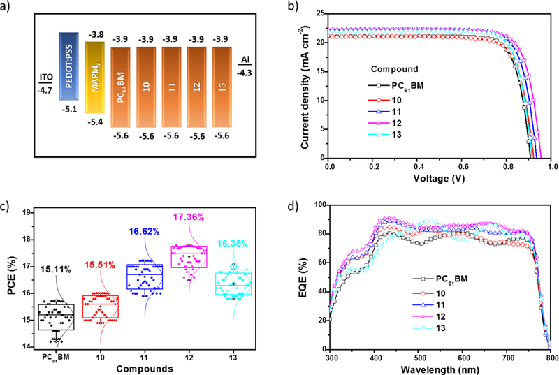
a) Schematic illustration of the estimated HOMO and LUMO energy levels, calculated from CV and UV-vis. b) J-V curves under 1 sun illumination (100 mW/cm2) in forward voltage scans. c) The PCE histograms measured for 48 independent cells. d) EQE spectra for the PSCs fabricated using compounds 10–13 and PC61BM as the ETMs.
Table 3.
Summary of device performance. The calculated Jsc values were obtained from the EQE curves. Values in parentheses represent the best PCEs measured.
| Compound | Calculated Jsc (mA/cm2) |
Jsc (mA/cm2) | Voc (V) | FF (%) | PCE (%) |
|---|---|---|---|---|---|
| PC61BM | 21.03 | 21.10 | 0.91 | 0.82 | 15.11±0.6 (15.74) |
| 10 | 20.85 | 21.00 | 0.93 | 0.82 | 15.51±0.5 (16.01) |
| 11 | 21.78 | 22.10 | 0.94 | 0.83 | 16.61±0.6 (17.22) |
| 12 | 22.19 | 22.30 | 0.96 | 0.83 | 17.36±0.4 (17.77) |
| 13 | 22.04 | 22.10 | 0.92 | 0.84 | 16.35±0.7 (17.08) |
Figure 4.
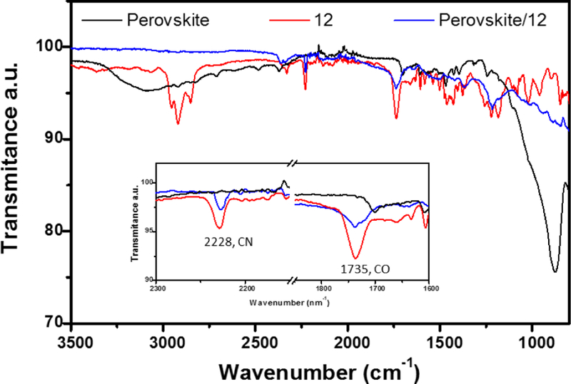
FTIR spectra of perovskite, compound 12 and the perovskite/12 films.
To probe the passivation ability of compounds 10–13 and the control PC61BM when deposited on the perovskite, we studied the photoluminescence (PL and TR-PL) of the photoactive layer (perovskite) with and without fullerenes. A significant PL quenching effect was observed for the perovskite layer coated with fullerenes 10–13 and PC61BM (Figure 5a). Compound 12 has a higher passivation ability than the other fullerenes, resulting in a more pronounced inhibition of the electron-hole recombination processes.31.
Figure 5.
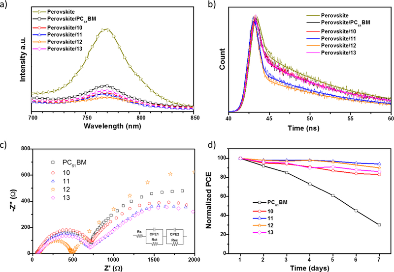
a) Steady-state PL spectra of the perovskite and perovskite/ETM films. b) TR-PL spectra of the perovskite and perovskite/ETM films. c) Nyquist plots of the PSCs based on compounds 10–13 and PC61BM as the ETMs. d) Normalized PCEs of PSCs measured as a function of time in ~20% humidity at room temperature.
Figure 5b shows the TR-PL decay measurements, monitoring the emission peak of the different fullerene derivative coated perovskite layers as a function of time. The pristine perovskite layer exhibits a PL lifetime of about 48.6 ns whereas perovskite/10, perovskite/11, perovskite/12, perovskite/13, and perovskite/PC61BM, exhibit PL lifetimes of 47.9, 46.7, 45.1, 47.8 and 47.9 ns, respectively. Faster decays are measured for the samples coated with the fullerenes, which shows that the charge transfer processes are much faster than the charge recombination process in the perovskite layer.31 The PL decay times are consistent with the observed PL quenching effect, suggesting that compound 12 has a better ability to suppress electron-hole recombination.
To further investigate the electrical and charge transport properties at the perovskite/fullerene interface, EIS was performed for PSCs based on compounds 10–13 and PC61BM (Figure 5c). The equivalent circuit used to fit the Nyquist plots is illustrated in figure 5c, the series resistance (Rs) corresponds to the resistance of the two electrodes, the charge-transport resistance (Rct) and the recombination resistance (Rrec) correspond to the resistances at the fullerene/perovskite interfaces as extensively reported elsewhere.32–34 As shown in figure 5c, PSCs based on 12 display a lower Rct and larger Rrec values than devices based on 10, 11, 13 and PC61BM and considering that all the fullerenes have similar electron mobility and HOMO/LUMO energy values, the PCE improvement for devices based on 12 must result from improved interfacial contact and charge transfer between the perovskite and the compound 12. These results demonstrate that electron extraction is more efficient at the perovskite/12 interface than that for perovskite/10, perovskite/11, perovskite/13 and perovskite/PC61BM. In addition, a large Rrec was found when using compound 12, which means that unfavourable recombination events occur at the perovskite/12 interface. These results are also consistent with the higher PL quenching observed for perovskite/12 films, which provide a rational explanation for the higher Jsc values.
The long term-device stabilities for PSCs were evaluated under ~20% humidity in air at room temperature without encapsulation for seven days (without continuous illumination). Figure 5d, shows the normalized PCEs against time. After seven days of periodic measurements, devices based on PC61BM lost 70% of their initial PCE. In contrast, devices based on compounds 10–13 lost less than 15% of their initial PCE under the same conditions.
Conclusions
In this work, new C60 fullerene derivatives functionalized with thiophene moieties as well as with electron donating or electron withdrawing groups bromine (Br) or cyano (CN), respectively, were synthesized via Bingel reactions and used as the ETMs in PSCs. We systematically studied the effect of the new fullerenes on PSCs performances by SCLC, FTIR, PL, TRPL, and EIS. The photoconversion efficiencies of PSCs based on compounds 10–13 were higher than those of devices based on PC61BM, which can be associated with the better passivation ability, due to specific interactions between S···Pb atoms. The best photovoltaic performance was achieved for devices based on compound 12 (cyano derivative), likely due the synergistic effect of its higher εr, lower interfacial resistance and specific interactions between the carbonyl and cyano groups of the fullerene and the perovskite layer as determined from EIS and FTIR, respectively. These results show the importance of designing and synthesizing new fullerenes for their use in efficient PSCs.
Supplementary Material
Acknowledgements
Authors thank the US National Science Foundation (NSF) for generous support of this work under the NSF-PREM program (DMR 1205302), CHE-1408865 (to L.E.) and 1401188 (to F. D.). The Robert A. Welch Foundation is also gratefully acknowledged for an endowed chair to L. E. (Grant AH-0033). Research reported in this paper was supported by the National Institute of General Medical Sciences of the National Institutes of Health under linked Award Numbers RL5GM118969, TL4GM118971, and UL1GM118970. The content is solely the responsibility of the authors and does not necessarily represent the official views of the National Institutes of Health.
Footnotes
Conflict of interest
There are no conflicts to declare.
References
- 1.NREL, Best Research-Cell Efficiencies, https://www.nrel.gov/pv/assets/images/efficiency-chart.png, (accessed April, 2018).
- 2.Hu X, Huang Z, Zhou X, Li P, Wang Y, Huang Z, Su M, Ren W, Li F, Li M, Chen Y and Song Y Adv. Mater 2017, 29, 1703236. [DOI] [PubMed] [Google Scholar]
- 3.Wang Y-C, Li X, Zhu L, Liu X, Zhang W and Fang J Adv. Energy Mater 2017, 7, 1701144. [Google Scholar]
- 4.Ghosh BK, Weoi CNJ, Islam A and Ghosh SK Renew. Sustainable Energy Rev 2018, 82, 1990–2004. [Google Scholar]
- 5.Bush KA, Palmstrom AF, Yu ZJ, Boccard M, Cheacharoen R, Mailoa JP, McMeekin DP, Hoye RLZ, Bailie CD, Leijtens T, Peters IM, Minichetti MC, Rolston N, Prasanna R, Sofia S, Harwood D, Ma W, Moghadam F, Snaith HJ, Buonassisi T, Holman ZC, Bent SF and McGehee MD Nat. Energy 2017, 2, 17009. [Google Scholar]
- 6.Castro E, Murillo J, Fernandez-Delgado O and Echegoyen L J. Mater. Chem. C 2018, 6, 2635–2651. [Google Scholar]
- 7.Nie W, Tsai H, Asadpour R, Blancon J-C, Neukirch AJ, Gupta G, Crochet JJ, Chhowalla M, Tretiak S, Alam MA, Wang H-L and Mohite AD Science 2015, 347, 522–525. [DOI] [PubMed] [Google Scholar]
- 8.Zheng X, Chen B, Dai J, Fang Y, Bai Y, Lin Y, Wei H, Zeng Xiao C. and Huang J Nat. Energy 2017, 2, 17102. [Google Scholar]
- 9.Castro E, Zavala G, Seetharaman S, D’Souza F and Echegoyen L J. Mater. Chem. A 2017, 5, 19485–19490. [DOI] [PMC free article] [PubMed] [Google Scholar]
- 10.Tian C, Castro E, Wang T, Betancourt-Solis G, Rodriguez G and Echegoyen L ACS Appl. Mater. Interfaces 2016, 8, 31426–31432. [DOI] [PubMed] [Google Scholar]
- 11.Chiang C-H, Nazeeruddin MK, Grätzel M and Wu C-G Energy Environ. Sci 2017, 10, 808–817. [Google Scholar]
- 12.Groeneveld BGHM, Najafi M, Steensma B, Adjokatse S, Fang H-H, Jahani F, Qiu L, Brink G. H. t., Hummelen JC and Loi MA APL Mater 2017, 5, 076103. [Google Scholar]
- 13.Tian C, Kochiss K, Castro E, Betancourt-Solis G, Han H and Echegoyen L Mater J Chem. A 2017, 5, 7326–7332. [Google Scholar]
- 14.Dong H, Wu Z, Xia B, Xi J, Yuan F, Ning S, Xiao L and Hou X Chem. Commun 2015, 51, 8986–8989. [DOI] [PubMed] [Google Scholar]
- 15.Fang Y, Bi C, Wang D and Huang J ACS Energy Lett 2017, 2, 782–794. [Google Scholar]
- 16.Gatti T, Menna E, Meneghetti M, Maggini M, Petrozza A and Lamberti F Nano Energy 2017.
- 17.Deng L-L, Xie S-Y and Gao F Adv. Electron. Mater 2017, 1700435.
- 18.Noel NK, Abate A, Stranks SD, Parrott ES, Burlakov VM, Goriely A and Snaith HJ ACS Nano 2014, 8, 9815–9821. [DOI] [PubMed] [Google Scholar]
- 19.Xu J, Buin A, Ip AH, Li W, Voznyy O, Comin R, Yuan M, Jeon S, Ning Z, McDowell JJ, Kanjanaboos P, Sun J-P, Lan X, Quan LN, Kim DH, Hill IG, Maksymovych P and Sargent EH Nat. Commun 2015, 6, 7081. [DOI] [PMC free article] [PubMed] [Google Scholar]
- 20.Shao S, Abdu-Aguye M, Qiu L, Lai L-H, Liu J, Adjokatse S, Jahani F, Kamminga ME, ten Brink GH, Palstra TTM, Kooi BJ, Hummelen JC and Antonietta Loi M Energy Environ. Sci 2016, 9, 2444–2452. [Google Scholar]
- 21.Zhang S, Zhang Z, Liu J and Wang L Adv. Funct. Mater 2016, 26, 6107–6113. [Google Scholar]
- 22.Jahani F, Torabi S, Chiechi RC, Koster LJA and Hummelen JC Chem. Commun 2014, 50, 10645–10647. [DOI] [PubMed] [Google Scholar]
- 23.Kollek T, Wurmbrand D, Birkhold ST, Zimmermann E, Kalb J, Schmidt-Mende L and Polarz S ACS Appl. Mater. Inter 2017, 9, 1077–1085. [DOI] [PubMed] [Google Scholar]
- 24.Zhang L, Yu F, Chen L and Li J Appl. Surf. Sci 2018, 443, 176–183. [Google Scholar]
- 25.Hummelen JC, Knight BW, Lepeq F, Wudl F, Yao J and Wilkins CL J. Org. Chem 1995, 60, 532–538. [Google Scholar]
- 26.Tian C, Castro E, Betancourt-Solis G, Nan Z-A, Fernandez-Delgado O, Jankuru S and Echegoyen L New J. Chem 2018, 42, 2896–2902. [Google Scholar]
- 27.Sun QJ, Wang HQ, Yang CH and Li YF J. Mater. Chem 2003, 13, 800–806. [Google Scholar]
- 28.Shao S, Liu J, Fang H-H, Qiu L, ten Brink GH, Hummelen JC, Koster LJA and Loi MA Adv. Energy Mater 2017, 1701305.
- 29.Murgatroyd PN J. Phys. D: Appl. Phys 1970, 3, 151. [Google Scholar]
- 30.Jiang Y, Li J, Xiong S, Jiang F, Liu T, Qin F, Hu L and Zhou Y J. Mater. Chem. A 2017, 5, 17632–17639. [Google Scholar]
- 31.Liang P-W, Liao C-Y, Chueh C-C, Zuo F, Williams ST, Xin X-K, Lin J and Jen AKY Adv. Mater 2014, 26, 3748–3754. [DOI] [PubMed] [Google Scholar]
- 32.Liu D, Yang J and Kelly TL J. Am. Chem. Soc 2014, 136, 17116–17122. [DOI] [PubMed] [Google Scholar]
- 33.Dualeh A, Moehl T, Tétreault N, Teuscher J, Gao P, Nazeeruddin MK and Grätzel M ACS nano 2013, 8, 362–373. [DOI] [PubMed] [Google Scholar]
- 34.Pitarch-Tena D, Ngo TT, Vallés-Pelarda M, Pauporté T and Mora-Seró I ACS Energy Lett 2018, 3, 1044–1048. [Google Scholar]
Associated Data
This section collects any data citations, data availability statements, or supplementary materials included in this article.


