Abstract
Hybrid positron emission tomography (PET)/magnetic resonance imaging (MRI) has risen to the cutting edge of medical imaging technology as it allows simultaneous acquisition of structural, functional and molecular information of the patient. A PET insert that can be installed into existing MR systems can in principle reduce the cost barriers for an existing MR site to achieve simultaneous PET/MRI compared to procuring an integrated PET+MRI system. The PET insert systems developed so far for PET/MRI require the RF transmitter coil to reside inside the PET ring as those PET inserts block the RF fields from the MRI system. Here we report for the first time on the performance of a full-ring brain-sized “RF-penetrable” PET insert we have recently completed. This insert allows the RF fields generated by the built-in body coil to penetrate the PET ring. The PET insert comprises a ring of 16 detector modules employing electro-optical coupled signal transmission and a multiplexing framework based on compressed sensing. Energy resolution, coincidence timing resolution (CTR), photopeak position, and coincidence count rate were acquired outside and inside a 3-Tesla MRI system under simultaneous acquisition to evaluate the impact of MRI on the PET performance. Coincidence count rate performance was evaluated by acquiring a cylinder source with high initial activity decaying over time. Tomographic imaging of two phantoms, a custom 6.5-cm diameter resolution phantom with hot rods of four different sizes (2.8 mm, 3.2 mm, 4.2 mm, and 5.2 mm diameter) and a 3D Hoffman brain phantom, were performed to evaluate the imaging capability of the PET insert. The energy resolution at 511 keV and CTR acquired by the PET insert were 16.2±0.1% and 5.3±0.1 ns FWHM, respectively, and remained stable during MRI operation except when the EPI sequence was applied. The PET system starts to show saturation in coincidence count rate at 2.76 million photon counts per second. Most of the 2.8-mm diameter hot rods and main features of the 3D Hoffman brain phantom were resolved by the PET insert, demonstrating its high spatial resolution and capability to image a complex tracer distribution mimicking that seen in the human brain.
Keywords: Positron emission tomography, PET, magnetic resonance imaging, MRI, insert, PET/MRI, RF-penetrable, compressed sensing, electro-optical
I. INTRODUCTION
COMBINING medical imaging modalities that measure complementary, multi-parametric information about a patient’s disease, such as anatomical and functional information in one study session has been proven to be of tremendous clinical value. For example, literature has shown that combining positron emission tomography (PET)/computed tomography (CT) improves staging and re-staging accuracies for major cancers by an average about 10% – 15% compared to using the two modalities separately [1].
Hybrid PET/magnetic resonance imaging (MRI) has recently risen to the cutting edge of medical imaging technology as it allows simultaneous acquisition of structural, functional and molecular information of the patient. Combining PET and MRI also offers several advantages over PET/CT. First, MRI provides better soft-tissue contrast than CT, making it a superior modality in imaging regions like brain [2], [3], head and neck [4], breast [5], liver [6], and pelvis [7], [8]. Second, unlike CT, MRI does not introduce ionization radiation. A recent study has shown that whole-body PET/CT scanning is accompanied by substantial radiation dose and cancer risk, with the CT component contributing between 54%–81% of the total combined dose [9]; in principle, this can be avoided by using MRI instead of CT to acquire anatomy information. This significant reduction of radiation dose can make PET/MRI a preferred modality for pediatric patients [10] and those requiring repeat studies. Third, unlike PET/CT, in which the two image sets are acquired sequentially, PET/MRI can be acquired simultaneously, allowing optimal temporal and spatial co-registration of the two data sets and correction of the patient motion observed in PET images based on timeresolved MRI images [11], which can improve the image quality, especially for cardiac imaging [12].
The challenges and different approaches to combine PET and MRI have been extensively reviewed in previous literature [13]–[22]. One approach to combine PET and MRI for simultaneous acquisition is to integrate PET and MRI into a single “PET+MRI” system, which is used in both commercial wholebody PET/MRI systems (Siemens Biograph mMR [23] and GE SIGNA PET/MR [24]). A single integrated system can in principle provide the best software and hardware integration, which has benefits regarding the clinical workflow. However, the huge investment to purchase both PET and MRI subsystems as well as make necessary room renovation has deterred most care providers from procuring an integrated PET+MRI system, limiting growth of the field.
The other approach is to develop an insertable PET system that can be installed into an MRI system to achieve simultaneous PET/MRI. The insert approach can in principle significantly lower the above-mentioned cost barriers for an existing MRI site to achieve simultaneous PET/MRI as it avoids the expensive integration and installation of both PET and MRI sub-systems. Several PET insert systems for PET/MRI have been developed for proof-of-concept [25], [26], imaging small animals [27]–[36] and human brains [37]–[40]. A separate bird-cage radio-frequency (RF) transceiver coil is often placed inside the PET ring to generate and receive RF fields as the Faraday cages used in these PET insert systems block the RF fields from the MRI system. This configuration results in less uniform RF transmit fields compared to using the built-in body coil as the RF transmitter [41].
A common clinical practice of head MRI is to use MRI built-in body coil as the RF transmitter and a local receiveonly multi-channel head coil as the RF receiver to achieve better sensitivity, and hence, signal-to-noise ratio (SNR) of the reconstructed MR images [42]. A multi-channel head coil also enables parallel imaging techniques to accelerate image acquisition [43]. To achieve this coil configuration (body coil transmit and head coil receive) with the insert approach for PET/MRI, the installed PET insert system has to be “RFpenetrable” to allow the RF fields from the body coil to penetrate through the PET insert and reach the subject. Our group has been working on such an “RF-penetrable” brainsized PET insert system.
In our previous work, we have reported the performance with just 2 PET detector modules, including details of the components used [44], and a compressed sensing multiplexing readout scheme for the detectors [45]. With the full-ring (16 detector modules) system completed, we have studied the impact of the PET insert on the MR performance [46]. We have also successfully acquired simultaneous PET and MRI images by using the body coil as both RF transmitter and receiver, demonstrating the “RF-penetrability” of the full-ring PET insert system (the RF fields had to enter inside and exit out of the PET ring) [47]. In this work, we present, for the first time, an evaluation of important system performance parameters for the full 16 detector ring insert system.
II. MATERIALS AND METHODS
A. RF-penetrable PET insert
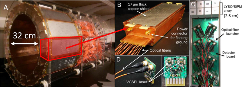
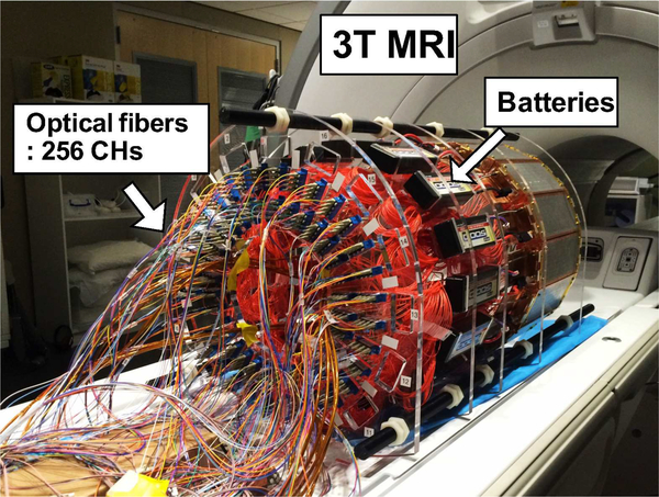
In brief, the prototype PET insert comprises 16 PET detector modules arranged in a 32 cm inner diameter ring with 1 mm inter-modular gaps (Fig. 1A) to allow the RF fields to leak in uniformly. Each detector module is encased in a copper Faraday cage with 1/2 oz (≈ 17 μm thick) copper plating (Fig. 1B) and comprises a 2×4 tiling configuration of arrays of 4×4 lutetium-yttrium-orthosilicate (LYSO) scintillation crystal elements (3.2 × 3.2 × 20 mm3) one-to-one coupled to earlygeneration silicon photomultiplier (SiPM) photodetector arrays (Fig. 1C, ArraySM-4 manufactured in 2008 by SensL, Cork, Ireland). The axial field-of-view (FoV) of the prototype PET insert is 2.8 cm. The signals of the 128 SiPM pixels in each of the 16 PET detector modules are multiplexed down to 16 output channels using a framework based on compressed sensing [45], [48], [49]. To electrically decouple the PET system from the MR system, the resulting electrical signals from the SiPM are converted into near infrared analog optical signals using non-magnetic vertical cavity surface-emitting lasers (VCSELs) (Fig. 1D) [50]. The 256 (16 × 16) analog optical signals are transmitted from inside the MRI bore through 20 meter length optical fibers to the data acquisition system residing in the adjacent control room [51].
Fig. 1.
(A) RF-penetrable PET insert. (B) PET detector Faraday cage with optical fibers exiting the end. Inside the cage is the (C) electro-optical PET detector module comprising 128 LYSO scintillation crystal elements covering 2.8-cm axial FoV each coupled one-to-one to SiPM pixels multiplexed to 16 optical signal transmission channels. (D) Optical fiber launchers each containing two non-magnetic vertical cavity surface emitting lasers (VCSELs).
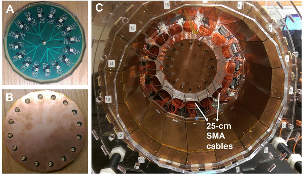
In our previous study of just two modules [44], we have seen a loss of counts in the PET detectors due to a small SiPM bias voltage droop during MRI operation when the RF pulses were applied. A new 16-channel SiPM bias voltage regulator module has since been developed to address this issue (Fig. 2). The design of the regulator module is based on a linear regulator (LT3013B, Linear Technology) with multiple stages of low-pass filter to reduce potential RF interference. The bias voltage to each of the 16 PET detector modules can be adjusted individually to optimize PET performance. The 16 outputs of the voltage regulator module are arranged in a circular pattern (see Fig. 2A) next to the PET ring matching the arrangement of the PET detector modules so that short (25-cm) cables can be used for connection (Fig. 2C) without crossing each other. This circular design further reduces potential sources of RF interference as long cables can act as antennas or form loops when crossed, which can pick up RF noise. The voltage regulator is also encased in a copper Faraday cage fabricated with a similar method as used for the PET detector modules (Fig. 2B).
Fig. 2.
16-channel voltage regulator module for SiPM bias arranged in a circular pattern (A) and encased in a Faraday cage (B), which allows using short (25-cm) SMA cables for power connection.
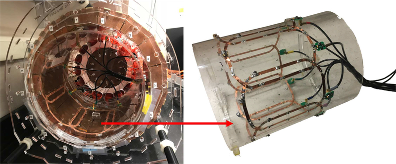
A custom 8-channel receive-only phased array coil has been developed to be placed inside the PET detector ring for better MRI sensitivity (Fig. 3). More details about the construction of the coil and the comparison of its performance to a custom bird-cage transceiver coil, which is used in most other PET inserts, can be found in our previous work [52].
Fig. 3.
A custom 8-channel receive-only phased array coil (right) was integrated into the PET ring (left).
B. PET performance evaluation
1). Energy and coincidence timing resolution:
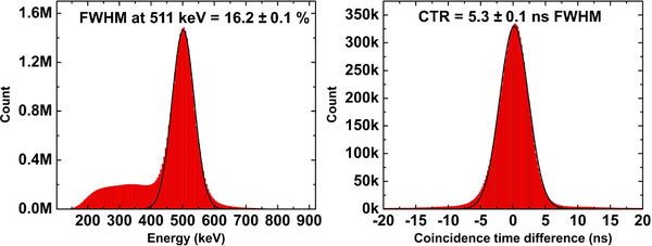
Coincidences were acquired with a 400 μCi 68Ge point source placed at the iso-center of the PET insert system to determine the energy and coincidence timing resolution (CTR). To correct for the difference in light output of the scintillators and gain of SiPMs, the photopeak in the energy spectrum acquired by each scintillator crystal and SiPM pixel was first normalized by multiplying a scale factor to each of the energy spectra from 2,048 pixels in the system to align the photopeak position. The normalized energy spectra from 2,048 pixels were then summed to plot the global energy spectrum for the system. The saturation effect of the SiPM was not corrected in this work. Energy resolution of the system was reported as the FWHM of the Gaussian curve fitted to the 511 keV photopeak in the global energy spectrum. To obtain the CTR, an energy window of 410 keV to 610 keV (approximately 2 × FWHM energy resolution centered at 511 keV) was applied to the acquired events before plotting the global coincidence timing spectrum. The CTR was reported as the FWHM of the Gaussian curve fitted to the energy-gated global coincidence timing spectrum.
2). Coincidence count rate:
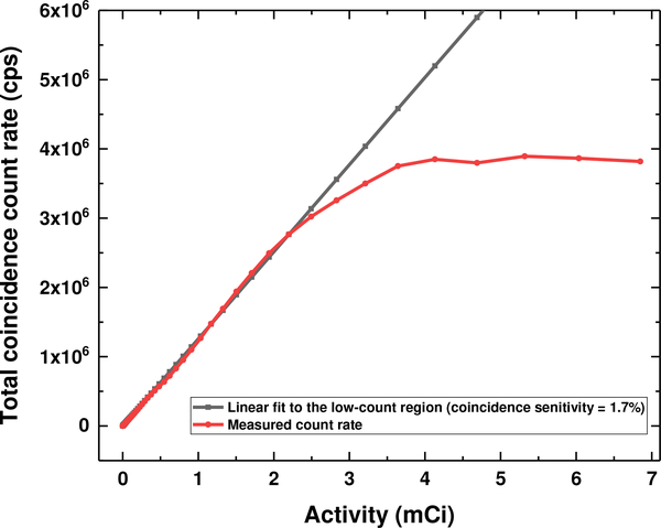
Total coincidence count rate performance of the system was evaluated by acquiring a cylinder source (1 milliliter 18F-FDG solution in a 5-milliliter syringe) placed at the isocenter of the system. Randome and scatter corrections were not applied in this experiment. The acquisition started with an initial activity of ≈7 mCi, which saturated the system, and continued until the activity decayed to background level. A coincidence window of 40 ns was implemented in the data acquisition system firmware. No energy-gating was applied beside the triggering threshold.
3). System performance stability:
The stability of the PET system was evaluated by measuring energy resolution, CTR, 511 keV photopeak position and coincidence counts within the photopeak every minute over 2 hours with the experimental setup described in the previous sub-section, and the same analysis method was used to determine the energy resolution and CTR. The PET system was powered and warmed up for 1.5 hours to reach thermal equilibrium with the ambient environment before the experiment.
4). Tomographic imaging:
Two phantoms were used to evaluate the image quality acquired by the PET insert system. The images were acquired with the phased array head coil inside the PET ring.
a). Spatial resolution phantom:
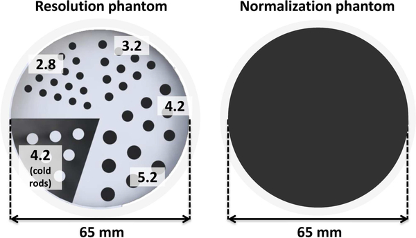
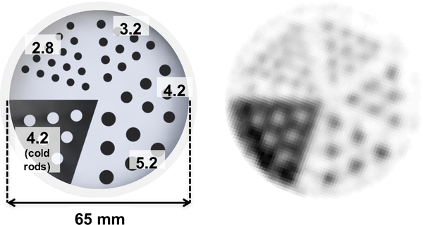
A custom 3D-printed 6.5cm diameter resolution phantom (Fig. 4, left) was fabricated from plastic (3D Systems VisiJet M3 clear) [53]. The phantom was printed with hot rods of four different sizes (2.8 mm, 3.2 mm, 4.2 mm, and 5.2 mm diameter) in a cold background, as well as 4.2-mm cold rods in a hot background. A normalization phantom was also fabricated, consisting of a uniform hot cylinder with the same outer dimensions as the resolution phantom (Fig. 4, right). The similar linear attenuation coefficients of water and plastic at 511 keV enable normalization scans of this phantom to also be used for attenuation correction. The resolution phantom was filled with ≈ 300 μCi (≈ 11.9 μCi/ml activity concentration). The normalization phantom was filled with ≈ 270 μCi (≈ 2.3 μCi/ml activity concentration). Approximately 33 and 36 million prompt coincidences were acquired and used in image reconstruction for resolution phantom and normalization phantom, respectively.
Fig. 4.
(Left) A custom 3D-printed 6.5-cm diameter resolution phantom comprising hot rods of different diameter (2.8 mm, 3.2 mm, 4.2 mm, and 5.2 mm) and 4.2-mm cold rods. (Right) The uniform cylinder phantom used for the normalization scan.
PET resolution phantom images were reconstructed using 3D list-mode OSEM (ordered subset expectation maximization) implemented on a GPU (graphics processing unit) [54]. Reconstruction was run with 10 subsets for 15 iterations, using 1.0 mm (x) × 1.0 mm (y) × 1.0 mm (z) voxels. An energy window of ≈ 410–610 keV and a coincidence time window of 10 ns were used. No scatter and random corrections were applied to this data set.
b). 3D Hoffman brain phantom:
A 3D Hoffman brain phantom was acquired to evaluate the capability of the PET insert system to image a complex tracer distribution [55]. The Hoffman brain phantom was filled with ≈ 1.57 mCi (≈ 1.3 μCi/ml activity concentration). Approximately 62 million prompt coincidences were acquired and used in image reconstruction. A normalization scan was acquired by imaging a uniform cylinder phantom with an inner diameter of 20.4 cm and a height of ≈ 3 cm, filled with ≈ 3.3 mCi (≈ 3.3 μCi/ml activity concentration), for 2 hours. Hoffman brain phantom images were reconstructed with 5 iterations and 10 subsets, using 1.0 mm × 1.0 mm × 2.0 mm voxels. The same energy and time window were used as described in the previous section. Random coincidences correction was performed by subtracting the counts acquired in the delayed coincidence window [56]. No scatter correction was applied to this data set.
5). PET system performance under simultaneous MR operation:
PET performance was evaluated inside a 3-Tesla MRI system (GE Healthcare Discovery MR750) under simultaneous MR operation (Fig. 5). Three common clinical MR pulse sequences were used: GRE (gradient echo), FSE (fast spin echo), and EPI (echo planar imaging). Table. I summarizes the parameters of the three MR pulse sequences.
Fig. 5.
PET insert on the patient bed of a 3T MRI system. The insert is powered with batteries and connected to the data acquisition system with 20 m length optical fibers. The data acquisition system resided in the adjacent control room.
Table I.
PARAMETERS OF THE MRI PULSE SEQUENCES USED IN THIS STUDY.
| Sequence | TR (ms) |
TE (ms) |
Voxel size (mm3) |
Matrix size | Readout bandwidth (Hz/Px) |
Flip angle (degree) |
|---|---|---|---|---|---|---|
| GRE | 3000 | 71 | 0.86 × 0.86 × 4.00 | 256 × 256 × 5 | 244.141 | 90 |
| FSE | 500 | 5 | 0.86 × 0.86 × 4.00 | 256 × 256 × 5 | 122.109 | 90 |
| EPI | 2000 | 30 | 3.44 × 3.44 × 4.00 | 64 × 64 × 5 | 7812.5 | 90 |
The analog optical signal output of a VCSEL in the PET detector module (Fig. 1D) was captured by a digital storage oscilloscope (Agilent DSO90254A) triggered by the MR RF pulses to directly observe the impact of RF pulses on the PET output waveforms.
Using a similar point-source experimental setup and the same analysis method as described in section II-B3, energy resolution, CTR, 511 keV photopeak position, and coincidence counts within the photopeak were measured every minute for 10 minutes under continuous operation of different MR pulse sequences.
III. RESULTS
A. Energy and coincidence timing resolution
Fig. 6 shows the global energy and coincidence timing spectra acquired by the 256-channel RF-penetrable PET insert system. The energy resolution at 511 keV and CTR of the system are 16.2 ± 0.1% and 5.3 ± 0.1 ns FWHM, respectively. The errors reported in both spectra correspond to the standard deviation over 5 separate measurements.
Fig. 6.
Global energy (left) and coincidence timing spectra (right) acquired by the RF-penetrable PET insert system.
B. Coincidence count rate
Fig. 7 shows the theoretical and measured coincidence count rate performance of the PET insert system with increasing activity. The theoretical coincidence count rate is derived by fitting the linear region of the coincidence count rate measured at low activity, resulting in an estimated coincidence sensitivity of 1.7% for this prototype PET system. The measured coincidence count rate started to deviate from the linear theoretical coincidence count rate at 2.2 mCi or 2.76 Mcps (million counts per second) and approached a peak value of 4 Mcps.
Fig. 7.
Theoretical (black) and measured (red) coincidence count rate acquired with a cylinder source decaying over time. The measured coincidence count rate deviates from the theoretical coincidence count rate when the activity (coincidence count rate) is larger than 2.2 mCi (2.76 Mcps).
C. System performance stability
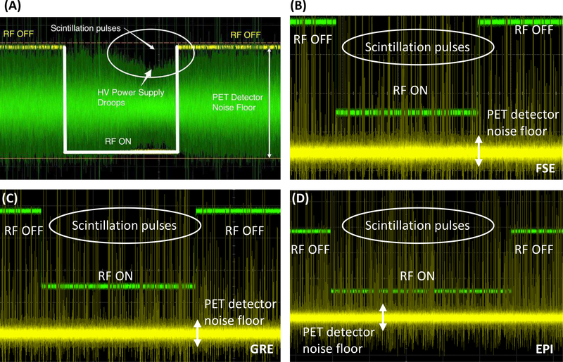
Fig. 8 shows the waveforms of the output signal from a VCSEL in the PET detector module during the MR RF pulse sequences before (A) and after (B–D) implementing the new SiPM bias voltage regulator module (Fig. 2). Without the voltage regulator module, the SiPM bias power supply drooped during the period when RF pulses were applied, which lowered the gain of the SiPM devices [44]. This issue was resolved after implementing the voltage regulator module (B–D of Fig. 8).
Fig. 8.
Waveforms of the output of a VCSEL in the PET detector module captured by a high performance digital storage oscilloscope synchronized to the RF trigger of the MRI system. (A) Waveform captured without the SiPM bias voltage regulator module during FSE sequence (adapted with permission from [44]). (B–D) Waveforms captured after implementing the voltage regulator module during FSE (B), GRE (C), and EPI (D) sequences. X-axis unit: 1 ms/interval. Y-axis unit: 50 mV/interval in (A) and 100 mV/interval in (B–D) (VCSEL output) and 1 V/interval (MRI RF pulse). The fact that there is no change to the analog PET detector pulses or noise floor with RF on or off as seen on oscilloscope waveforms is perhaps the strongest evidence to support the claim that the PET detectors are free of interference from the MR system.
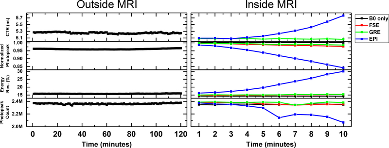
The left panel of Fig. 9 shows the CTR, photopeak position, energy resolution, and coincidence counts within the photopeak window measured every minute for 2 hours outside the MRI system. The right panel of Fig. 9 shows the same performance metrics acquired under continuous application of three different MR sequences, each for 10 minutes. Table II summarizes the mean and maximum difference of each performance metric over the measurement period acquired outside and inside MRI under the different RF pulse sequences. The maximum differences of CTR, photopeak position, energy resolution, and coincidence photopeak counts acquired outside MRI are 0.08 ns, 0.008, 0.38%, and 0.05M, respectively, showing that the performance of the PET insert system was stable during the 2-hour measurement. The performance of the PET insert was stable during the 10-minute periods the FSE and GRE sequences were applied and was comparable to the performance measured without applying any RF pulses (B0 only). However, by the end of the 10-minute EPI sequence, the CTR increased from 5.1 ns to 5.8 ns, the normalized photopeak position shifted toward a lower value by 15%, the energy resolution at 511 keV increased from 16.2% to 30.0%, and the photopeak count decreased from 2.38M to 2.07M (-13%).
Fig. 9.
Coincidence timing resolution (CTR), normalized 511 keV photopeak position, energy resolution, and photopeak counts of the RF-penetrable PET insert system measured over a period of two hours outside the MRI system (left) and inside the MRI system (right). For the measurement performed inside the MRI system, typical MRI pulse sequences were applied, each continuously for 10 minutes. (FSE: Fast spin echo; GRE: Gradient echo; EPI: Echo planar imaging)
Table II.
SUMMARY OF THE STABILITY MEASUREMENTS ACQUIRED OUTSIDE AND INSIDE MRI.
| MR condition | CTR | Photopeak position | Energy resolution | Photopeak count | ||||
|---|---|---|---|---|---|---|---|---|
| Mean (ns) | Max.−Min. (ns) | Mean | Max.−Min. | Mean (%) | Max.−Min. (%) | Mean | Max.−Min. | |
| Outside MRI | 5.25 | 0.08 | 0.96 | 0.008 | 16.0 | 0.38 | 2.36M | 0.05M |
| B0 only | 4.93 | 0.03 | 1.00 | 0.005 | 14.7 | 0.25 | 2.35M | 0.02M |
| GRE | 5.07 | 0.02 | 0.99 | 0.012 | 15.2 | 0.44 | 2.38M | 0.05M |
| FSE | 4.91 | 0.05 | 0.99 | 0.018 | 15.0 | 0.59 | 2.36M | 0.04M |
| EPI | 5.29 | 0.69 | 0.92 | 0.144 | 21.7 | 13.75 | 2.23M | 0.31M |
D. Tomographic imaging
1). Spatial resolution phantom:
Fig. 10 shows the dimensions and the reconstructed images of the custom 3D-printed resolution phantom. All 3.2-mm diameter hot rods and most of the 2.8-mm diameter hot rods can be resolved.
Fig. 10.
Dimensions and reconstructed images of the custom 3D-printed resolution phantom (unit: mm).
2). 3D Hoffman brain phantom:
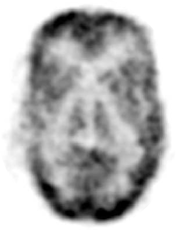
Fig. 11 shows a preliminary reconstructed image of the 3D Hoffman brain phantom, demonstrating the capability of the PET insert to image a complex tracer distribution mimicking that seen in the human brain. At the desired 1×1×2 mm3 image resolution, the image quality is limited by low statistics (62 million prompt coincidences), owing to the low photon sensitivity for the 2.8 cm PET axial FOV.
Fig. 11.
Reconstructed image of 3D Hoffman brain phantom.
IV. DISCUSSION
Compared to the results acquired with 2 detector modules [45], the energy resolution (16.2 ± 0.1%) and CTR 5.3 ± 0.1 ns) of the full ring 16 detector module system degraded by 0.8% (in absolute percentage) and 0.8 ns, respectively. This degradation is expected as the system scales up due to larger variation in performance (e.g. SiPM gain) across a larger number of electronic components. Additional timing jitter can also be added to the system as additional electronic components are required to synchronize multiple detector modules. Factors limiting the CTR have been studied in our previous work [45].
The coincidence count rate of the PET system starts to show saturation at 2.76 Mcps resulting from a 2.2 mCi cylinder source with negligible tissue absorption placed at the isocenter of the system. This result indicates that the coincidence count rate performance of the PET system is sufficient for typical PET brain scans, which typically have lower than 2 mCi activity distributed in the brain in addition to more photon attenuation than the syringe phantom used in this study [57], [58]. The coincidence count rate of the PET system approached a peak value of 4 Mcps, which is mainly limited by the 1 Gigabit Ethernet between the data acquisition system and the workstation (4 Mcps × 240 bits per event = 0.96 Gigabit per second). If required, the count rate performance of the PET insert system can be easily improved by upgrading the Ethernet protocol to, for example, 10 Gigabit Ethernet.
The voltage regulator module was not properly shielded in our previous work [44], causing the bias voltage to the SiPMs to drop when MR RF pulses were applied (Fig. 8A). As a result, the coincidence count rate dropped by 3.9% and 11.4% during the GRE and FSE pulse sequences, respectively, as the drop in SiPM bias voltage causes some of the original photopeak events to occur outside the energy window. The new voltage regulator with multiple stages of low-pass filter placed inside a Faraday cage (Fig. 2) remedied this issue (Fig. 8B–D). The fact that there is no change to the analog PET detector pulses or noise floor with RF pulses demonstrated using actual oscilloscope waveforms is perhaps the strongest evidence to support any claim that PET detectors are free of interference from the MR system in a PET/MR system. No drop of coincidence count rate was observed during the GRE and FSE sequences after implementing the new voltage regulator module (Fig. 9, right).
The energy resolution, CTR, and photopeak count rate remain stable under continuous application of FSE and GRE sequences for 10 minutes and are comparable to those measured without RF pulses (Fig. 9, right). The difference between the maximum and minimum values of photopeak position and energy resolution are larger when FSE and GRE sequences are running than that measured without RF pulses running, which can be due to the slight temperature increase of the detectors due to pulse sequence-induced eddy current. The slightly better CTR acquired (4.9 ns vs. 5.3 ns) and higher normalized photopeak in the MRI than outside MRI are due to lower ambient temperature of the magnet room. This demonstrates that sufficient shielding effectiveness of the Faraday cages and modifications to the power cables and the voltage regulators prevent PET detectors from picking up RF interference from the MRI. The impact of operating PET electronics on the MRI performance has been studied and reported in our previous work [46].
However, the energy resolution and CTR degraded gradually during the 10-minute EPI sequence. A downward shift of photopeak was also observed as the scan progressed. As a result, it causes the loss of photopeak counts as some events shifted out of the energy window. This degradation is mainly due to the eddy currents induced in the Faraday cages when the gradient-intensive EPI sequence was applied, which heats up the detector module and the SiPMs, causing the gain of the SiPMs to drop and the dark counts to increase. A new Faraday cage design made with phosphor bronze mesh is expected to reduce eddy current generation while maintaining high shielding effectiveness [59]. We are also implementing active liquid cooling of the detectors to further mitigate effects of any remaining gradient heating.
Most of the hot rods with 2.8 mm diameter can be resolved in the reconstructed resolution phantom image (Fig. 10). This result is also in par or better than that reported by Hong, et. al. [38], who have demonstrated the capability to resolve 3.5-mm diameter hot rods with their brain-sized PET insert for PET/MRI, which uses slightly smaller crystal elements (3.0 mm instead of 3.2 mm used in this work). These results demonstrate the superior spatial resolution that can be achieved with a brain-dedicated system using smaller crystal elements compared to commercial integrated whole-body PET/MRI systems that achieve 4–5 mm spatial resolution [23], [60].
Main features of the 3D Hoffman brain phantom can be seen in Fig. 11, demonstrating the capability of the PET insert to image a complex tracer distribution. However, there is some room for improvement. First, the top and bottom edges of the reconstructed Hoffman brain phantom image show unusual activity that is higher than other regions (Fig. 11). This artifact may be due to problems with using a uniform cylinder phantom for normalization and attenuation correction [61], which will likely be mitigated by using an annulus source configuration instead of a cylinder [62]. Second, applying scatter correction to the data set can further improve image quality (e.g. contrast) and accuracy. A Monte Carlo-based scatter correction [63] is under development for the PET insert. Finally, the short axial field-of-view (2.8 cm) and low sensitivity of the system limit the photon statistics, and hence the SNR of the reconstructed image. This can be improved by extending the axial field-of-view and improving the timing resolution to enable time-of-flight measurement to increase effective sensitivity [64]. Based on our previous work [45], the timing resolution of the system can be improved by using state-of-the-art SiPM technology with higher photo detection efficiency, reading out the SiPM without multiplexing to preserve the SNR, and increasing the bandwidth of the readout circuits. The impact of MRI measurement on PET images has been studied in our previous work [47].
V. CONCLUSIONS
We have developed and evaluated the performance of a radio-frequency field-penetrable PET insert for simultaneous PET/MRI. The PET insert studied in this work comprises a full ring of 16 detector modules employing electro-optical coupled signal transmission and a multiplexing framework based on compressed sensing. A receive-only phased array head coil has been developed and integrated with the PET insert. The system energy resolution at 511 keV and coincidence timing resolution acquired by the PET insert are 16.2 ± 0.1% and 5.3 ± 0.1 ns, respectively. The coincidence count rate capability of the PET insert, which starts to show saturation at 2.76 Mcps, is sufficient for typical brain PET scans. A voltage regulator module mitigated the RF interference and photopeak count loss during MR RF pulses. The performance of the PET insert is stable both outside and inside the MR system during simultaneous PET and MR operation except when the EPI sequence was applied, where eddy currents induced in the Faraday cages heated up the detector modules, degrading the PET performance. The PET insert can resolve 2.8-mm diameter hot rods. Main features of a 3D Hoffman brain phantom can be resolved by the PET insert, demonstrating its capability to image a complex tracer distribution mimicking that seen in the human brain. Simultaneous PET/MR imaging studies with the MR images acquired by using the body coil as the RF transmitter and the head coil as the receiver are the subject of current and future work.
ACKNOWLEDGMENTS
The authors would like to thank Ronald D. Watkins at Stanford Radiological Sciences Laboratory for his help with the MRI experiments and Dr. Ealgoo Kim for his help with the data acquisition system. This work was supported in part by NIH-NIBIB Grants R01 EB01946501 and F31 EB020504, a NIH-NCI Grant T32 CA009695, a Ministry of Education of Taiwan graduate fellowship, and a Stanford-Coulter translational research grant.
Contributor Information
Chen-Ming Chang, Departments of Applied Physics and Radiology, Stanford University, Stanford, CA, USA.
Brian J. Lee, Departments of Mechanical Engineering and Radiology, Stanford University, Stanford, CA, USA.
Alexander M. Grant, Departments of Bioengineering and Radiology, Stanford University, Stanford, CA, USA.
Andrew N. Groll, Department of Radiology, Stanford University, Stanford, CA, USA.
Craig S. Levin, Departments of Radiology, Electrical Engineering, Bioengineering and Physics, Stanford University, Stanford, CA, USA, cslevin@stanford.edu).
REFERENCES
- [1].Czernin J, Allen-Auerbach M, and Schelbert HR, “Improvements in cancer staging with pet/ct: Literature-based evidence as of september 2006,” Journal of Nuclear Medicine, vol. 48, no. 1 suppl, pp. 78S–88S, 2007. [PubMed] [Google Scholar]
- [2].Buchbender C, Heusner TA, Lauenstein TC, Bockisch A, and Antoch G, “Oncologic PET/MRI, Part 1: Tumors of the Brain, Head and Neck, Chest, Abdomen, and Pelvis,” Journal of Nuclear Medicine, vol. 53, no. 6, pp. 928–938, Jun. 2012. [Online]. Available: http://jnm.snmjournals.org/content/53/6/928.abstract [DOI] [PubMed] [Google Scholar]
- [3].Barthel H, Schroeter ML, Hoffmann K-T, and Sabri O, “PET/MR in Dementia and Other Neurodegenerative Diseases,” Seminars in Nuclear Medicine, vol. 45, no. 3, pp. 224–233, May 2015. [Online]. Available: http://www.sciencedirect.com/science/article/pii/S0001299814001469 [DOI] [PubMed] [Google Scholar]
- [4].Queiroz MA, Hllner M, Kuhn F, Huber G, Meerwein C, Kollias S, von Schulthess G, and Veit-Haibach P, “PET/MRI and PET/CT in follow-up of head and neck cancer patients,” European Journal of Nuclear Medicine and Molecular Imaging, vol. 41, no. 6, pp. 1066–1075, 2014. [DOI] [PubMed] [Google Scholar]
- [5].Grueneisen J, Nagarajah J, Buchbender C, Hoffmann O, Schaarschmidt BM, Poeppel T, Forsting M, Quick HH, Umutlu L, and Kinner S, “Positron Emission Tomography/Magnetic Resonance Imaging for Local Tumor Staging in Patients With Primary Breast Cancer: A Comparison With Positron Emission Tomography/Computed Tomography and Magnetic Resonance Imaging,” Investigative Radiology, vol. 50, no. 8, 2015. [DOI] [PubMed] [Google Scholar]
- [6].Melsaether AN, Raad RA, Pujara AC, Ponzo FD, Pysarenko KM, Jhaveri K, Babb JS, Sigmund EE, Kim SG, and Moy LA, “Comparison of Whole-Body 18f FDG PET/MR Imaging and Whole-Body 18f FDG PET/CT in Terms of Lesion Detection and Radiation Dose in Patients with Breast Cancer,” Radiology, vol. 281, no. 1, pp. 193–202, Mar. 2016. [DOI] [PMC free article] [PubMed] [Google Scholar]
- [7].Freitag M, Radtke J, Hadaschik B, Kopp-Schneider A, Eder M, Kopka K, Haberkorn U, Roethke M, Schlemmer H-P, and AfsharOromieh A, “Comparison of hybrid 68ga-PSMA PET/MRI and 68gaPSMA PET/CT in the evaluation of lymph node and bone metastases of prostate cancer,” Eur J Nucl Med Mol Imaging, vol. 43, no. 1, pp. 70–83, Jan. 2016. [DOI] [PubMed] [Google Scholar]
- [8].Beiderwellen K, Grueneisen J, Ruhlmann V, Buderath P, Aktas B, Heusch, Kraff O, Forsting M, Lauenstein TC, and Umutlu L,“[18f]FDG PET/MRI vs. PET/CT for whole-body staging in patients with recurrent malignancies of the female pelvis: initial results,” European Journal of Nuclear Medicine and Molecular Imaging, vol. 42, no. 1, pp. 56–65, 2015. [DOI] [PubMed] [Google Scholar]
- [9].Huang B, Law MW-M, and Khong P-L, “Whole-Body PET/CT Scanning: Estimation of Radiation Dose and Cancer Risk,” Radiology, vol. 251, no. 1, pp. 166–174, Apr. 2009. [DOI] [PubMed] [Google Scholar]
- [10].Schfer JF, Gatidis S, Schmidt H, Gckel B, Bezrukov I, Pfannenberg CA, Reimold M, Ebinger M, Fuchs J, Claussen CD, and Schwenzer NF, “Simultaneous Whole-Body PET/MR Imaging in Comparison to PET/CT in Pediatric Oncology: Initial Results,” Radiology, vol. 273, no. 1, pp. 220–231, May 2014. [DOI] [PubMed] [Google Scholar]
- [11].Catana C, “Motion Correction Options in PET/MRI,” Seminars in Nuclear Medicine, vol. 45, no. 3, pp. 212–223, May 2015. [DOI] [PMC free article] [PubMed] [Google Scholar]
- [12].Petibon Yoann and Guehl Nicolas J and Reese Timothy G and Ebrahimi Behzad and Normandin Marc D and Shoup Timothy M and Alpert Nathaniel M and El Fakhri Georges and Ouyang Jinsong, “Impact of motion and partial volume effects correction on PET myocardial perfusion imaging using simultaneous PET-MR,” Physics in Medicine and Biology, vol. 62, no. 2, p. 326, 2017. [DOI] [PMC free article] [PubMed] [Google Scholar]
- [13].Lee BJ, Chang C-M, and Levin CS, “PET System Technology Designs for Achieving Simultaneous PET/MRI,” in PET/MRI in Oncology: Current Clinical Applications, Iagaru A, Hope T, and Veit-Haibach P, Eds. Cham: Springer International Publishing, 2018, pp. 1–26, dOI: 10.1007/978-3-319-68517-5_1. [DOI] [Google Scholar]
- [14].Vandenberghe Stefaan and Marsden Paul K, “PET-MRI: a review of challenges and solutions in the development of integrated multimodality imaging,” Physics in Medicine and Biology, vol. 60, no. 4, p. R115, 2015. [Online]. Available: http://stacks.iop.org/0031-9155/60/i=4/a=R115 [DOI] [PubMed] [Google Scholar]
- [15].Pichler BJ, Wehrl HF, Kolb A, and Judenhofer MS, “Positron emission tomography/magnetic resonance imaging: The next generation of multimodality imaging?” Seminars in Nuclear Medicine, vol. 38, no. 3, pp. 199–208, May 2008. [Online]. Available: ://WOS:000254801900006http://ac.els-cdn.com/S000129980800024X/1-s2.0-S000129980800024X-main.pdf?_tid=aa62afac-2afa-11e3-bc28-00000aab0f27&acdnat=1380674364_4a3c9d08476c955110c0bf8e33955abf [DOI] [PMC free article] [PubMed] [Google Scholar]
- [16].Zaidi H and Guerra AD, “An outlook on future design of hybrid PET/MRI systems,” Medical Physics, vol. 38, no. 10, pp. 5667–5689, 2011. [Online]. Available: 10.1118/1.3633909 [DOI] [PubMed] [Google Scholar]
- [17].Vaska P and Cao T, “The State of Instrumentation for Combined Positron Emission Tomography and Magnetic Resonance Imaging,” Seminars in Nuclear Medicine, vol. 43, no. 1, pp. 11–18, Jan. 2013. [Online]. Available: http://www.sciencedirect.com/science/article/pii/S0001299812000797 [DOI] [PubMed] [Google Scholar]
- [18].Delso G and Ziegler S, “PET/MRI system design,” Eur J Nucl Med Mol Imaging, vol. 36, no. 1, pp. 86–92, Mar. 2009. [Online]. Available: 10.1007/s00259-008-1008-6 [DOI] [PubMed] [Google Scholar]
- [19].Jung JH, Choi Y, and Im KC, “PET/MRI: Technical Challenges and Recent Advances,” Nuclear Medicine and Molecular Imaging, pp. 1–10, 2016. [Online]. Available: 10.1007/s13139-016-0393-1 [DOI] [PMC free article] [PubMed] [Google Scholar]
- [20].Cabello J and Ziegler SI, “Advances in PET/MR Instrumentation and Image Reconstruction,” BJR, p. 20160363, Jul. 2016. [Online]. Available: 10.1259/bjr.20160363 [DOI] [PMC free article] [PubMed] [Google Scholar]
- [21].Herzog H, Pietrzyk U, Shah NJ, and Ziemons K, “The current state, challenges and perspectives of MR-PET,” NeuroImage, vol. 49, no. 3, pp. 2072–2082, Feb. 2010. [Online]. Available: http://www.sciencedirect.com/science/article/pii/S1053811909011070 [DOI] [PubMed] [Google Scholar]
- [22].Disselhorst JA, Bezrukov I, Kolb A, Parl C, and Pichler BJ, “Principles of PET/MR Imaging,” Journal of Nuclear Medicine, vol. 55, no. Supplement 2, pp. 2S–10S, Jun. 2014. [Online]. Available: http://jnm.snmjournals.org/content/55/Supplement2/2S.abstract [DOI] [PubMed] [Google Scholar]
- [23].Delso G, Furst S, Jakoby B, Ladebeck R, Ganter C, Nekolla SG, Schwaiger M, and Ziegler SI, “Performance Measurements of the Siemens mMR Integrated Whole-Body PET/MR Scanner,” Journal of Nuclear Medicine, vol. 52, no. 12, pp. 1914–1922, Dec. 2011. [DOI] [PubMed] [Google Scholar]
- [24].Grant AM, Deller TW, Khalighi MM, Maramraju SH, Delso G, and Levin CS, “NEMA NU 2–2012 performance studies for the SiPMbased ToF-PET component of the GE SIGNA PET/MR system,” Medical Physics, vol. 43, no. 5, pp. 2334–2343, 2016. [DOI] [PubMed] [Google Scholar]
- [25].Shao YP, Cherry SR, Farahani K, Meadors K, Siegel S, Silverman RW, and Marsden PK, “Simultaneous PET and MR imaging,” Physics in Medicine and Biology, vol. 42, no. 10, pp. 1965–1970, Oct. 1997. [Online]. Available: ://WOS:A1997YB30200010http://iopscience.iop.org/0031-9155/42/10/010/pdf/0031-91554210010.pdf [DOI] [PubMed] [Google Scholar]
- [26].Shao Y, Cherry SR, Farahani K, Slates R, Silverman RW, Meadors K, Bowery A, Siegel S, Marsden PK, and Garlick PB, “Development of a PET detector system compatible with MRI/NMR systems,” IEEE Transactions on Nuclear Science, vol. 44, no. 3, pp. 1167–1171, Jun. 1997. [Google Scholar]
- [27].Catana C, Wu Y, Judenhofer MS, Qi J, Pichler BJ, and Cherry SR, “Simultaneous Acquisition of Multislice PET and MR Images: Initial Results with a MR-Compatible PET Scanner,” Journal of Nuclear Medicine, vol. 47, no. 12, pp. 1968–1976, Dec. 2006. [Online]. Available: http://jnm.snmjournals.org/content/47/12/1968.abstract [PubMed] [Google Scholar]
- [28].Judenhofer MS, Catana C, Swann BK, Siegel SB, Jung W-I, Nutt RE, Cherry SR, Claussen CD, and Pichler BJ, “PET/MR Images Acquired with a Compact MR-compatible PET Detector in a 7-T Magnet,” Radiology, vol. 244, no. 3, pp. 807–814, Sep. 2007. [Online]. Available: 10.1148/radiol.2443061756 [DOI] [PubMed] [Google Scholar]
- [29].Sri Harsha M, Smith SD, Sachin SJ, Daniela S, Sean S, Bosky R, Martin LP, Sergio R, Sudeepti S, Jean-Franois P, Paul V, Craig LW, and David JS, “Small animal simultaneous PET/MRI: initial experiences in a 9.4 T microMRI,” Physics in Medicine and Biology, vol. 56, no. 8, p. 2459, 2011. [Online]. Available: http://stacks.iop.org/0031-9155/56/i=8/a=009 [DOI] [PubMed] [Google Scholar]
- [30].Yamamoto Seiichi and Watabe Tadashi and Watabe Hiroshi and Aoki Masaaki and Sugiyama Eiji and Imaizumi Masao and Kanai Yasukazu and Shimosegawa Eku and Hatazawa Jun, “Simultaneous imaging using Si-PM-based PET and MRI for development of an integrated PET/MRI system,” Physics in Medicine and Biology, vol. 57, no. 2, p. N1, 2012. [Online]. Available: http://stacks.iop.org/0031-9155/57/i=2/a=N1 [DOI] [PubMed] [Google Scholar]
- [31].Yoon HS, Ko GB, Il Kwon S, Lee CM, Ito M, Song IC, Lee DS, Hong SJ, and Lee JS, “Initial Results of Simultaneous PET/MRI Experiments with an MRI-Compatible Silicon Photomultiplier PET Scanner,” Journal of Nuclear Medicine, vol. 53, no. 4, pp. 608–614, Apr. 2012. [Online]. Available: ://WOS:000302377300043http://jnm.snmjournals.org/content/53/4/608.full.pdf [DOI] [PubMed] [Google Scholar]
- [32].Bjoern W, Pierre G, Christoph WL, Jakob W, Torsten S, Benjamin G, Jane EM, Paul KM, Fabian K, Michael P, Dirk H, and Volkmar S, “MR compatibility aspects of a silicon photomultiplierbased PET/RF insert withintegrated digitisation,” Physics in Medicine and Biology, vol. 59, no. 17, p. 5119, 2014. [Online]. Available: http://stacks.iop.org/0031-9155/59/i=17/a=5119 [DOI] [PubMed] [Google Scholar]
- [33].Weissler B, Gebhardt P, Duppenbecker P, Wehner J, Schug D, Lerche C, Goldschmidt B, Salomon A, Verel I, Heijman E, Perkuhn M, Heberling D, Botnar R, Kiessling F, and Schulz V, “A Digital Preclinical PET/MRI Insert and Initial Results,” Medical Imaging, IEEE Transactions on, vol. PP, no. 99, pp. 1–1, 2015. [DOI] [PubMed] [Google Scholar]
- [34].Schug David and Lerche Christoph and Weissler Bjoern and Gebhardt Pierre and Goldschmidt Benjamin and Wehner Jakob and Dueppenbecker Peter Michael and Salomon Andre and Hallen Patrick and Kiessling Fabian and Schulz Volkmar, “Initial PET performance evaluation of a preclinical insert for PET/MRI with digital SiPM technology,” Physics in Medicine and Biology, vol. 61, no. 7, p. 2851, 2016. [Online]. Available: http://stacks.iop.org/0031-9155/61/i=7/a=2851 [DOI] [PMC free article] [PubMed] [Google Scholar]
- [35].Ko GB, Yoon HS, Kim KY, Lee MS, Yang BY, Jeong JM, Lee DS, Song IC, Kim S.-k., Kim D, and Lee JS, “Simultaneous Multiparametric PET/MRI with Silicon Photomultiplier PET and Ultra-High-Field MRI for Small-Animal Imaging,” Journal of Nuclear Medicine, vol. 57, no. 8, pp. 1309–1315, Aug. 2016. [Online]. Available: http://jnm.snmjournals.org/content/57/8/1309.abstract [DOI] [PubMed] [Google Scholar]
- [36].Goertzen AL, Stortz G, Thiessen JD, Bishop D, Khan MS, Kozlowski P, Retire F, Schellenberg G, Shams E, Sossi V, and Thompson CJ, “First Results From a High-Resolution Small Animal SiPM PET Insert for PET/MR Imaging at 7t,” IEEE Transactions on Nuclear Science, vol. 63, no. 5, pp. 2424–2433, Oct. 2016. [Google Scholar]
- [37].Schlemmer H-PW, Pichler BJ, Schmand M, Burbar Z, Michel C, Ladebeck R, Jattke K, Townsend D, Nahmias C, Jacob PK, Heiss W-D, and Claussen CD, “Simultaneous MR/PET Imaging of the Human Brain: Feasibility Study,” Radiology, vol. 248, no. 3, pp. 1028–1035, Sep. 2008. [Online]. Available: http://pubs.rsna.org/doi/abs/10.1148/radiol.2483071927 [DOI] [PubMed] [Google Scholar]
- [38].Key Jo H, Yong C, Jin Ho J, Jihoon K, Wei H, Hyun Keong L, Yoonsuk H, Sangsu K, Ji Woong J, Kyu Bom K, Myung Sung S, and Hyun-wook P, “A prototype MR insertable brain PET using tileable GAPD arrays,” Medical Physics, vol. 40, no. 4, pp. 042503 (12 pp.)–042503 (12 pp.), Apr. 2013. [DOI] [PubMed] [Google Scholar]
- [39].Jung J, Choi Y, Jung JH, Kim S, and Im KC, “Performance evaluation of neuro-PET using silicon photomultipliers,” Nuclear Instruments and Methods in Physics Research Section A: Accelerators, Spectrometers, Detectors and Associated Equipment, vol. 819, pp. 182–187, May 2016. [Online]. Available: http://www.sciencedirect.com/science/article/pii/S0168900216300225 [Google Scholar]
- [40].Nishikido F, Fujiwara M, Tashima H, Akram M, Suga M, Obata T, and Yamaya T, “Development of a full-ring add-on PET prototype: A head coil with DOI-PET detectors for integrated PET/MRI,” Nuclear Instruments and Methods in Physics Research Section A: Accelerators, Spectrometers, Detectors and Associated Equipment, vol. 863, no. Supplement C, pp. 55–61, Aug. 2017. [Online]. Available: http://www.sciencedirect.com/science/article/pii/S0168900217305351 [Google Scholar]
- [41].Zanche ND, Birdcage Volume Coil Design. American Cancer Society, 2011. [Online]. Available: https://onlinelibrary.wiley.com/doi/abs/10.1002/9780470034590.emrstm1288
- [42].Wiggins GC, Triantafyllou C, Potthast A, Reykowski A, Nittka M, and Wald LL, “32channel 3 Tesla receiveonly phasedarray head coil with soccerball element geometry,” Magnetic Resonance in Medicine, vol. 56, no. 1, pp. 216–223, Jun. 2006. [Online]. Available: 10.1002/mrm.20925 [DOI] [PubMed] [Google Scholar]
- [43].Pruessmann KP, Weiger M, Scheidegger MB, and Boesiger, “SENSE: Sensitivity encoding for fast MRI,” Magnetic Resonance in Medicine, vol. 42, no. 5, pp. 952–962, 1999. [Online]. Available: 10.1002/(SICI)1522-2594(199911)42:5h952::AID-MRM16i3.0.CO [DOI] [PubMed] [Google Scholar]
- [44].Olcott Peter, Kim Ealgoo, Hong Keyjo, Lee Brian J., Grant Alexander M, Chen-Ming and, Glover Gary, and Levin Craig S., “Prototype positron emission tomography insert with electro-optical signal transmission for simultaneous operation with MRI,” Physics in Medicine and Biology, vol. 60, no. 9, p. 3459, 2015. [DOI] [PubMed] [Google Scholar]
- [45].Chang Chen-Ming and Grant Alexander M and Lee Brian J and Kim Ealgoo and Hong KeyJo and Levin Craig S, “Performance characterization of compressed sensing positron emission tomography detectors and data acquisition system,” Physics in Medicine and Biology, vol. 60, no. 16, p. 6407, 2015. [DOI] [PubMed] [Google Scholar]
- [46].Lee BJ, Grant AM, Chang CM, Watkins RD, Glover GH, and Levin CS, “MR performance in the presence of a radio frequencypenetrable positron emission tomography (PET) insert for simultaneous PET/MRI,” IEEE Transactions on Medical Imaging, vol. PP, no. 99, pp. 1–1, 2018. [DOI] [PMC free article] [PubMed] [Google Scholar]
- [47].Grant AM, Lee BJ, Chang C-M, and Levin CS, “Simultaneous PET/MR imaging with a radio frequency-penetrable PET insert,” Medical Physics, vol. 44, no. 1, pp. 112–120, 2017. [DOI] [PMC free article] [PubMed] [Google Scholar]
- [48].Olcott PD, Chinn G, and Levin CS, “compressed sensing for the multiplexing of pet detectors,” in 2011 IEEE Nuclear Science Symposium and Medical Imaging Conference, ser. ieee nuclear science symposium conference record new york: IEEE, 2011, pp. 3224–3226. [Google Scholar]
- [49].Chinn G, Olcott PD, and Levin CS, “Sparse Signal Recovery Methods for Multiplexing PET Detector Readout,” Medical Imaging, IEEE Transactions on, vol. 32, no. 5, pp. 932–942, 2013. [DOI] [PubMed] [Google Scholar]
- [50].Olcott PD, Peng Hao, and Levin CS, “Novel Electro-Optical Coupling Technique for Magnetic Resonance–Compatible Positron Emission Tomography Detectors,” Molecular Imaging, vol. 8, no. 2, pp. 74–86, Apr. 2009. [Online]. Available: https://search.ebscohost.com/login.aspx?direct=true&db=aph&AN=41038313&site=ehost-live&scope=site [PubMed] [Google Scholar]
- [51].Ealgoo K, Key Jo H, Olcott PD, and Levin CS, “PET DAQ system for compressed sensing detector modules,” Oct. 2012, pp. 2798–2801. [Online]. Available: http://ieeexplore.ieee.org/ielx7/6531926/6551044/06551638.pdf?tp=&arnumber=6551638&isnumber=6551044 [Google Scholar]
- [52].Lee B, Grant A, Chang C-M, Watkins R, and Levin C, “MR performance evaluation of an RF-penetrable PET insert with integrated RF receive coil for simultaneous PET/MRI,” Journal of Nuclear Medicine, vol. 56, no. supplement 3, pp. 1854–1854, May 2015. [Online]. Available: http://jnm.snmjournals.org/content/56/supplement_3/1854.abstract [Google Scholar]
- [53].Bieniosek MF, Lee BJ, and Levin CS, “Technical Note: Characterization of custom 3d printed multimodality imaging phantoms,” Medical Physics, vol. 42, no. 10, pp. 5913–5918, 2015. [Online]. Available: 10.1118/1.4930803 [DOI] [PMC free article] [PubMed] [Google Scholar]
- [54].Cui J.-y., Pratx G, Prevrhal S, and Levin CS, “Fully 3d list-mode time-of-flight PET image reconstruction on GPUs using CUDA,” Medical Physics, vol. 38, no. 12, pp. 6775–6786, 2011. [Online]. Available: http://scitation.aip.org/content/aapm/journal/medphys/38/12/10.1118/1.3661998 [DOI] [PubMed] [Google Scholar]
- [55].Hoffman EJ, Cutler PD, Digby WM, and Mazziotta JC, “3-D phantom to simulate cerebral blood flow and metabolic images for PET,” IEEE Transactions on Nuclear Science, vol. 37, no. 2, pp. 616–620, Apr. 1990. [Google Scholar]
- [56].Casey ME and Hoffman EJ, “Quantitation in Positron Emission Computed Tomography: 7. A Technique to Reduce Noise in Accidental Coincidence Measurements and Coincidence Efficiency Calibration.” Journal of Computer Assisted Tomography, vol. 10, no. 5, 1986. [PubMed] [Google Scholar]
- [57].Boellaard R, Delgado-Bolton R, Oyen WJG, Giammarile F, Tatsch K, Eschner W, Verzijlbergen FJ, Barrington SF, Pike LC, Weber WA, Stroobants S, Delbeke D, Donohoe KJ, Holbrook S, Graham MM, Testanera G, Hoekstra OS, Zijlstra J, Visser E, Hoekstra CJ, Pruim J, Willemsen A, Arends B, Kotzerke J, Bockisch A, Beyer T, Chiti A, and Krause BJ, “FDG PET/CT: EANM procedure guidelines for tumour imaging: version 2.0,” European Journal of Nuclear Medicine and Molecular Imaging, vol. 42, no. 2, pp. 328–354, Feb. 2015. [Online]. Available: 10.1007/s00259-014-2961-x [DOI] [PMC free article] [PubMed] [Google Scholar]
- [58].Minoshima S, Drzezga AE, Barthel H, Bohnen N, Djekidel M, Lewis DH, Mathis CA, McConathy J, Nordberg A, Sabri O, Seibyl JP, Stokes MK, and Van Laere K, “SNMMI Procedure Standard/EANM Practice Guideline for Amyloid PET Imaging of the Brain 1.0,” Journal of Nuclear Medicine, vol. 57, no. 8, pp. 1316–1322, Aug. 2016. [Online]. Available: http://jnm.snmjournals.org/content/57/8/1316.short [DOI] [PubMed] [Google Scholar]
- [59].Lee BJ, Watkins RD, Chang C-M, and Levin CS, “Low eddy current RF shielding enclosure designs for 3t MR applications,” Magnetic Resonance in Medicine, vol. 79, no. 3, pp. 1745–1752, 2018. [Online]. Available: 10.1002/mrm.26766 [DOI] [PMC free article] [PubMed] [Google Scholar]
- [60].Grant AM, Deller TW, Khalighi MM, Maramraju SH, Delso G, and Levin CS, “NEMA NU 2–2012 performance studies for the SiPMbased ToF-PET component of the GE SIGNA PET/MR system,” Medical Physics, vol. 43, no. 5, pp. 2334–2343, 2016. [DOI] [PubMed] [Google Scholar]
- [61].Cui J, “Fast and accurate pet image reconstruction on parallel architectures,” Ph.D. dissertation, Stanford University, 2013. [Google Scholar]
- [62].Mollet P, Keereman V, Bini J, Izquierdo-Garcia D, Fayad ZA, and Vandenberghe S, “Improvement of Attenuation Correction in Time-of-Flight PET/MR Imaging with a Positron-Emitting Source,” Journal of Nuclear Medicine, vol. 55, no. 2, pp. 329–336, Feb. 2014. [DOI] [PMC free article] [PubMed] [Google Scholar]
- [63].Levin CS, Dahlbom M, and Hoffman EJ, “A Monte Carlo correction for the effect of Compton scattering in 3-D PET brain imaging,” IEEE Transactions on Nuclear Science, vol. 42, no. 4, pp. 1181–1185, Aug. 1995. [Google Scholar]
- [64].Surti S and Karp JS, “Advances in time-of-flight PET,” Physica Medica, vol. 32, no. 1, pp. 12–22, Jan. 2016. [DOI] [PMC free article] [PubMed] [Google Scholar]


