Abstract
In this study, we sought to describe a novel imaging apparatus that is lightweight, inexpensive, and highly effective for use in colorectal diagnostic and treatment settings. Typical probes for use in colorectal ultrasonic imaging applications are developed for surgeons to diagnose and stage rectal tumors and image the rectum and anus. Here we outline a new technique and use it for colorectal imaging in an animal. This technique involves use of an ultrasound array module positioned along the axis of rotation such that improved rotation is possible. This module is in the shape of a linear rod with a rotary linear component that allows for emission of focused ultrasonic echo signals from a linear section of the probe. The usability of the transducer and rectal image quality are satisfactory in a porcine model with the technique proposed here, axial/lateral resolution as 0.96/2.24 mm with 6 dB applied through the contour map using the point spread function. When compared to currently available methods, this technique provides superior diagnostic 3D volumetric image quality with reduced acquisition time. Given this, the ultrasound device proposed here may prove a viable and preferable method to those currently available for urology and colorectal imaging applications.
Keywords: Ultrasonic imaging, Urology, Rotary linear probe, Dynamic focusing, Resolution
Introduction
Conventional ultrasound systems have been used over the past several decades for the assessment of anatomical features and diagnoses of diseases in radiology, cardiology, obstetrics/gynecology, and other specialties. Much research and development has focused on increasing the resolutions and frame rates of these imaging methods. However, there is also a growing demand for specialized diagnostic devices. The use of such techniques for diagnosis of urological, rectal, anal, and perineal disorders in particular has become increasingly valuable. Intra rectal ultrasonography is the most widely used and effective diagnostic tool for current colorectal cancer. The accuracy of this technique across numerous trials and meta-analyses ranges from 80 to 95% for T-staging and 70 to 75% for N-staging, levels that are slightly higher than the respective 75–85% and 60–70% observed for magnetic resonance imaging (MRI) [1, 2]. In many departments, the urological application of endoscopic examination is undervalued and not performed in all patients. Ultrasounds can rapidly provide information about a variety of bowel diseases. As a widely available, cross sectional imaging modality, ultrasound also serves to inform further examinations and treatment. In addition, ultrasound screening of asymptomatic patients can result in the identification of bowel pathologies such as colon cancer or anal disease [3]. Ultrasound examination of the bowel is a safe, widely available, inexpensive, noninvasive imaging technique that allows for real-time examination without the use of ionizing radiation and can be performed at any time [4]. The greatest disadvantage presented by this imaging modality is that it is highly dependent on operator experience and expertise, more so than sonographic evaluation, for example [5]. Additionally, some anatomical features can be more difficult to visualize and assess including the prostate, colon, rectum, uterus, and cervix. Those areas and others with more granular bodies are frequently the subject of diagnostic testing, which, if restricted, can be inaccurate. For these reasons, we have designed a new probe and display module frame [6] to support and enable ultrasound-based diagnosis in the fields of urology and coloproctology.
Materials and methods
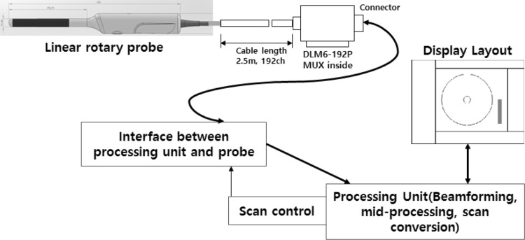
Figure 1 illustrates the configuration of the probe and the corresponding display module for rectal ultrasonic imaging, as proposed here. From a systems design perspective, the design of the console configuration is intended to support the proposed ultrasonic probe via an ultrasonic diagnostic console system. The basic module transmits the control signal between the diagnostic console system module and the probe, and is the interface between the transmission and reception signals. The probe and the diagnostic console system are designed to interface directly and a software structure mode is also configured for being coupled to a special linear probe to project a circular display by processing incoming echo signals to fit the corresponding display frame. The rotation of the linear probe is controlled via a field-programmable gate array on the motor control portion of the displaying module device in the diagnostic console system.
Fig. 1.
Configuration for the special probe and the corresponding displaying module device in the diagnostic console system
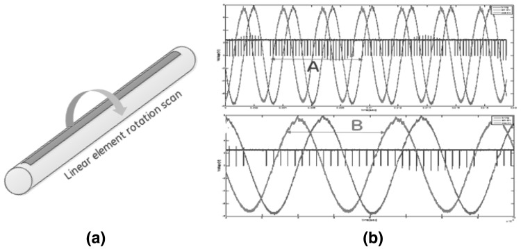
The motor dynamics are controlled such that motor operation steps are driven to match each transmission pulse, which further matches the system’s trigger time. The driving step motor and transmission signal are used to obtain an echo signal based on the transmission pulse, and are further synchronized such that one spherical image is generated by every 360-degree rotation of the probe. The control signals to the step motor via the system trigger are initiated as depicted in Fig. 2. As shown in Fig. 2, the basic operation of the motor is based on control signals comprising cosine and sine curves. In this case, there is synchronization with the trigger signal, which is the basic operation signal of the diagnostic console system. The number of system trigger signals constituting a circular image during one cycle of the control signal is shown in panels A and B in Fig. 2b. The number of system trigger signals can be changed based on the driving speed of the motor. When the motor operates at higher speed, the periodic signal of the motor control signal is reduced. This leads to a smaller number of system triggers and an increase in the frame rate of the circular image. In contrast, when the motor is driven more slowly, the number of system triggers increases and the frame rate of the circular image decreases.
Fig. 2.
a Rotary direction of probe and b control signals of step motor
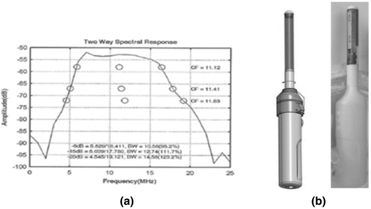
The acoustic module for the special transducer proposed here was developed by determining the acoustic properties of the module’s configuration to optimize the area to be imaged. The acoustic stack design was confirmed by selection of an optimum material and piezoceramic source. Layer coupling and the lead zirconate titanate construction of the body was used in designing the appropriate acoustics. The high-impedance dematching layer directs most of the acoustic energy from the piezoceramic forward through the matching layers, reducing the need for a high-attenuation backing using epoxy with aluminum oxide filler. The frequency response of this acoustic element in the 4.5-11.5 MHz (6 dB) band is shown in Fig. 3a.
Fig. 3.
a Frequency band for acoustic material and b model and prototype for rotary linear transducer
The special transducer proposed here is composed of a motor driven by only the rotation, and the horizontal movement is using the electric signal of the linear transducer. On the other hand, in the current method, one motor for rotation and another motor for horizontally moving are designed for the scanning operation, so that the operation configuration and design are easy, but the convenience aspect of the user’s diagnosis is very inconvenient in terms of the size and weight of the probe. Table 1 shows the comparison between the commercialized current way and our proposed way.
Table 1.
Comparison table between commercialized current method and our proposed method
| Commercialized current way | Out proposal way | |
|---|---|---|
| Design configuration |

|

|
| Volume frame rate | Low | High |
| Design difficulty | Easy | High |
| Sagittal plane resolution | Low | High |
| Transverse plane resolution | Mid | Low |
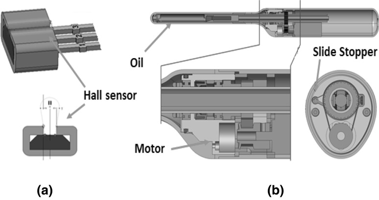
This was a concern given the required small motor size and limited weight of the probe. Furthermore, the electrical transduction elements of the transducer, dedicated to electrical transmission and reception, were designed with a cooling mechanism to maintain the durability and internal temperature of the probe so that it could be rotated for an extended period of time while maintaining its connection to flexible electric circuit material. The initial position of the linear transducer was controlled via a Hall sensor that was mechanically configured such that the corresponding transducer element was recognized and set as it approached the desired anatomical area. The acoustic elements of the linear rotary probe were designed to be contained within the probe’s outer casing, which was further configured to be filled with oil. As illustrated in Fig. 4, a slide stopper was designed to stop the probe’s rotation.
Fig. 4.
a Shape of Hall sensor and b the motor and Slide stopper in the rotary linear probe
Figure 5 shows that independent focusing of the rotary linear probe was accomplished by focusing on a specific location at a specific depth. A circular scan line was obtained by acquiring echo signal data, which was then formatted in a 2D circular image. The echo scan lines were then processed and converted into a circular shape after various filter processing steps, such as scale change and signal-to-noise ratio enhancement processing, including filtering using a specific radio frequency filter designed based on the transducer’s characteristics. The size of the aperture in the probe was adjusted based on the probe’s distance from the surface to the scan’s target site such that the transmission beams converged at the target site. As such, target areas nearer the surface of the probe were associated with smaller apertures and corresponding channel transmission signals. Conversely, more distal target areas were captured using larger aperture openings such that more channel transmission signals were transmitted. Beam focusing was performed based on the depths of the incoming signals. Wave fronts were dynamically transmitted and received across depths. Because of this transmission and reception strategy, we expected better resolution in the axial direction and greater image penetration than probes designed with only a single element.
Fig. 5.
The dynamical focusing of the rotary linear probe
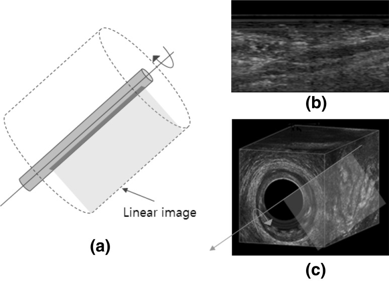
The method proposed here allows for the rapid resolution of a three-dimensional (3D) circular volume image by rotating a two-dimensional (2D) rectangle image 360°. This method is very attractive because it enables imaging of a specific lesion site using a linear image and simultaneously performing 3D volumetric imaging. This allows for stereoscopically viewing the lesion. Collection of this volumetric image can be performed more easily, which is an additional user benefit (Fig. 6).
Fig. 6.
a Model implementing a 3D circular image by rotating a 2D rectangle image 360° in a linear image, b 2D linear image and c 3D circular volume image
Results
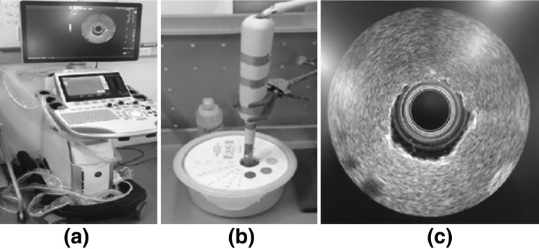
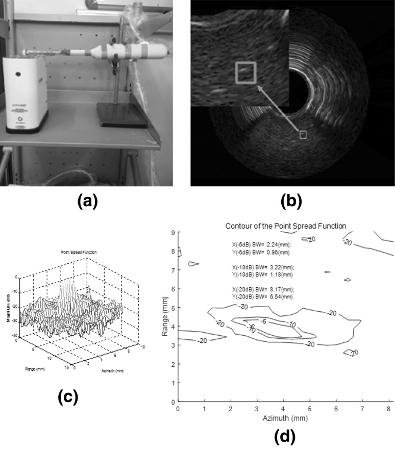
Figure 7 shows sample experimental results from a circular commercial phantom (Rectal Scan Phantom 504, ATS; Bridgeport, CT, USA) coupled to the probe described in the present study to confirm the appearance of the collected circular image before further resolution experimentation. With this configuration, we measured the device’s imaging resolution using a commercial phantom (Multi-purpose 403LE, Gammex; Middleton, WI, USA). The axial resolution obtained using this technique was 0.96 mm and the lateral resolution was 2.24 mm with 6 dB applied through the contour map using the point spread function outlined in Fig. 8 and Table 2 shows the results of comparing images obtained using a commercial phantom (Multi-purpose 403LE, Gammex; Middleton, WI, USA).
Fig. 7.
a Ultrasonic diagnostic system to support a colorectal application, b rotary linear probe with commercial phantom (ATS 504 model) and c 2D circle image for phantom
Fig. 8.
a Commercial phantom (GAMMEX 403LE model), b corresponding 2D circle image, c point spread function of the rectangle of (b) and d contour map of point spread function for resolution
Table 2.
Comparison of measured values with 6 dB applied through contour map using point spread function in the acquired images between current way and proposed way
| Item | Current way | Proposed way | Resolution increasing ratio |
|---|---|---|---|
| Lateral resolution (mm) | 1.89 | 2.24 | − 0.156 |
| Axial resolution (mm) | 1.70 | 0.96 | 0.771 |
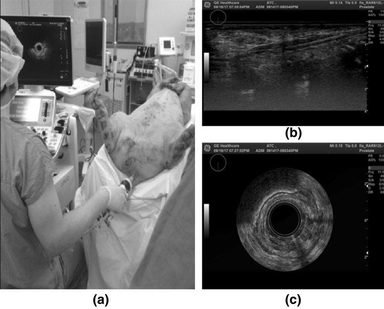
The quality of the real scanned image obtained using this method and its convenient use for animal experimentation are depicted in Fig. 9. Animal scanning demonstrated the ease with which this lightweight transducer can be used to confirm the diagnosis within a circular region in a selected anatomical area. The provision of linear image information may be beneficial for the confirmation of distinct image components and can provide details necessary for diagnosis. However, given that this device is a prototype, further image optimization is necessary before commercialization can be achieved.
Fig. 9.
Lateral/Axial Scanning image of an animal’s rectal area using our designed special probe and a a prototype ultrasonic diagnostic system, b the upper right is a linear image, and c the lower right is the circular image
Discussion and conclusion
As described above, we expected that the design of the linear rotary probe and the prototype system supporting it would be of considerable help to users in the diagnosis of rectal and anal diseases. We plan to further develop related technologies while minimizing some of the disadvantages of the device described below by performing further phantom and animal experiments.
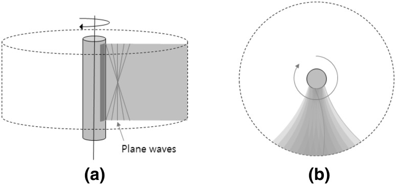
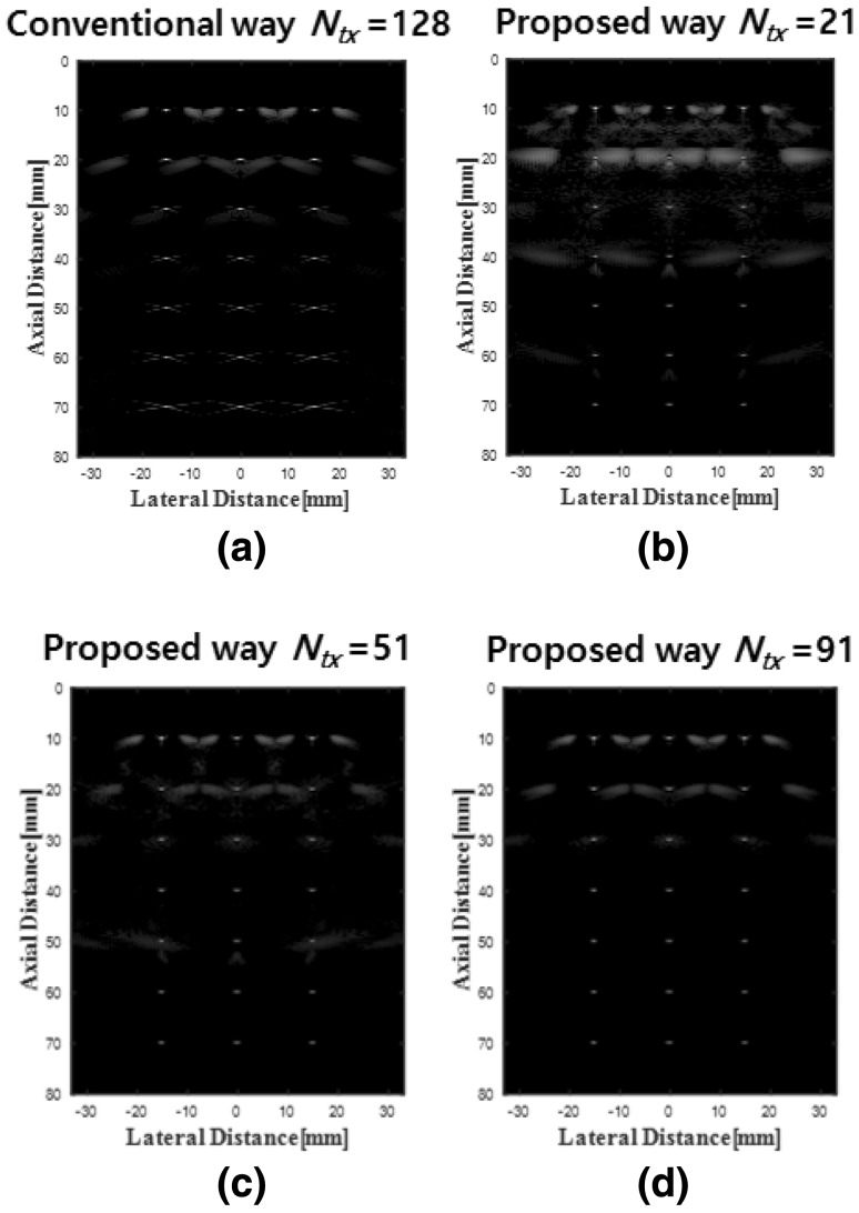
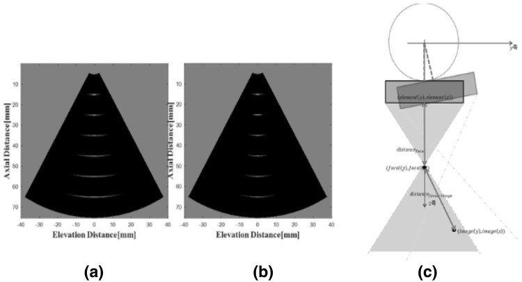
The linear rotary probe proposed here is composed of relatively few elements and captures a wide field of view due to the limited space that its wired connections occupy. Furthermore, the pitch of its elements relative to the imaging frequency of the linear array probe results in grating lobe artifacts, which occur when the pitch of the element is larger than half of the wavelength [7]. We attempted to minimize these artifacts using dynamic transmission. This technique, which comprises focusing on a transverse plane, can be carried out by synthetic focusing on a plurality of virtual sound sources generated by the rotation of the linear probe. This enables not only high-speed image acquisition, but also good image quality, via transmission on plane waves. Synthetic focusing involves lateral focusing, as illustrated in Fig. 10. Better resolution can be achieved with synthetic focusing, as shown in Fig. 11. The method used here to improve image quality, which comprises application of the synthetic aperture technique in the elevational direction, can be very effective, as demonstrated in Fig. 12. Filed II [8, 9] and MATLAB (The Math Works, Natick, MA, USA) were extensively used to simulate beamforming, and the dynamic transmission focusing technique [10–12] was used to reduce grating lobes for different element sizes and to achieve a higher frame rate and better image quality.
Fig. 10.
a Lateral focusing using plane wave synthetic focusing, b elevational focusing using synthetic focusing
Fig. 11.
a Conventional way with #128 of TX, b proposed way with #21 of TX, c proposed way with #51 of TX, and d proposed way with #91 of TX
Fig. 12.
a The image of conventional way, b the image of proposed way and c the proposed synthetic aperture way in the elevational direction
Acknowledgements
This research was supported by the ATC Global Convergence Program (2015-6-10053241) through the Korea Evaluation Institute of Industrial Technology (KEIT) funded by the Korean Ministry of Trade, Industry and Energy. We thank two anonymous referees for helpful suggestions on a previous version of this manuscript.
Conflict of interest
All the authors declare that they have no conflicts in relation to the work in this article.
Ethical approval
All animal procedures were performed in accordance with the approval by the appropriate Institutional Animal Care and Use Committee (IACUC).
Contributor Information
Jeong Seok Kim, Email: jeongseok.kim@ge.com.
Jong Gun Lee, Email: JongGun.Lee@ge.com.
Jae Hyeok Choi, Email: jaehyeok.choi@ge.com.
Bong Hyo Han, Email: BongHyo.Han@ge.com.
Se Leang Yoon, Email: seleang.yoon@ge.com.
Ho Jung, Email: ho.jung@humanscan.co.kr.
Tai Kyong Song, Email: tksong@sogang.ac.kr.
Jae Young Lee, Email: leejy4u@gmail.com.
References
- 1.Eldelman BR, Weiser MR. Endorectal ultrasound: its role in the diagnosis and treatment of rectal cancer. Clin Colon Rectal Surg. 2008;21(3):167–177. doi: 10.1055/s-2008-1080996. [DOI] [PMC free article] [PubMed] [Google Scholar]
- 2.Ptok H, Marusch F, Meyer F, et al. Feasibility and accuracy of TRUS in the pre-treatment staging for rectal carcinoma in general practice. Eur J Surg Oncol. 2006;32:420–425. doi: 10.1016/j.ejso.2006.01.014. [DOI] [PubMed] [Google Scholar]
- 3.Bor R, Fabian A, Szepes Z. Role of ultrasound in colorectal diseases. World J Gastroenterol. 2016;22(43):9477–9487. doi: 10.3748/wjg.v22.i43.9477. [DOI] [PMC free article] [PubMed] [Google Scholar]
- 4.Muradali D, Goldberg DR. US of gastrointestinal tract disease. Radiographics. 2015;35:50–68. doi: 10.1148/rg.351140003. [DOI] [PubMed] [Google Scholar]
- 5.Novak KL, Wilson SR. Sonography for surveillance of patients with Crohn disease. J Ultrasound Med. 2012;31:1147–1152. doi: 10.7863/jum.2012.31.8.1147. [DOI] [PubMed] [Google Scholar]
- 6.Kim J-S, et al, Rotary linear transducer. Domestic Patent (10-2016-0046816/10-1797910), PCT (PCT/KR2016/006239), US (15/490.326).
- 7.Steinberg BD. Principles of aperture and array system design. New York: Wiley; 1976. p. 74. [Google Scholar]
- 8.Jensen JA. Field: a program for simulating ultrasound systems. In: Proceedings of the 10th Nordic-Baltic conference on biomedical engineering, vol. 34, 1996. p. 51–3.
- 9.Jensen JA, Svendsen NB. Calculation of pressure fields from arbitrarily shaped, apodized, and excited ultrasound transducers. IEEE Trans Ultrason Ferrol Freq Control. 1992;39(2):262–267. doi: 10.1109/58.139123. [DOI] [PubMed] [Google Scholar]
- 10.Chen Y, Lou Y, Yen J. Dynamic transmit-receive beamforming by spatial matched filtering for ultrasound imaging with plane wave transmission. Ultrason Imaging. 2017;39(4):207–223. doi: 10.1177/0161734617692017. [DOI] [PubMed] [Google Scholar]
- 11.Montaldo G, et al. Coherent plane-wave compounding for very high frame rate ultrasonography and transient elastography. IEEE Trans Ultrason Ferrol Freq Control. 2009;56(3):489–506. doi: 10.1109/TUFFC.2009.1067. [DOI] [PubMed] [Google Scholar]
- 12.Bae S, et al. An optimized plane wave synthetic focusing imaging for high-resolution convex array imaging. In: IEEE international ultrasonic symposium proceedings, vol. 0498, 2015. p. 8182–4.


