Abstract
To treat atrial fibrillation (AFib), radiofrequency ablation is usually implemented with a cardiac catheter to block abnormal electrical signals from pulmonary veins. However, it is challenging to manipulate a passive catheter. In addition, the radiation exposure to patients under fluoroscopic guidance has been a concern. To address these two major issues, this work presents the development of a steerable and MRI-compatible cardiac catheter by using shape memory alloy (SMA) as an alternative interventional tool for AFib. The developed cardiac catheter is comprised of a passive and flexible tubing and a steerable tip. The tip is composed of multiple bending modules and each module is actuated by a pair of antagonistic SMA wires. To improve the MRI-compatibility of SMA actuators, the electric current required for SMA actuation is significantly reduced by developing a technique of conductive heating actuation. In this paper, the design and fabrication of the cardiac catheter are presented, followed by modeling the SMA bending module. The working performance of the SMA bending module is experimentally studied. In the end, a proof-of-concept demonstration of the cardiac catheter is performed in an explanted heart.
Keywords: Surgical robotics: steerable catheters/needles, medical robots and systems, mechanism design
I. INTRODUCTION
A TRIAL fibrillation (AFib) is a common heart-related health problem among American population [1]. Ectopic electrical discharge from pulmonary veins (PVs) in the left atrium (LA) is a significant factor that triggers AFib [2]. To treat AFib, a radiofrequency (RF) ablation catheter is usually employed to ablate the tissue around PVs to block ectopic electrical signals [3], [4]. However, it requires high expertise to perform the procedure using a conventional cardiac catheter with limited steerability. The catheter has to be inserted and retracted many times along with base rotation to precisely reach an ablation target and apply appropriate contact force [4]. To improve steerability, the tendon driven technique has been extensively researched for cardiac catheters [5], [6] and applied in some commercial products. In a typical tendon-driven cardiac catheter, multiple pairs of tendons are anchored at different bending segments and remotely pulled to control the curvature of each segment [5], [6]. However, the coupling effect among different segments has impeded its further application to realize a robust and highly maneuverable cardiac catheter with high DoFs.
Shape memory alloy (SMA) has become another actively researched actuation technique for steerable catheters, endoscopes, and cannulas. Among early works, a series of active catheters with a diameter of 0.5 mm to 2.8 mm were developed by bonding multiple micro SMA springs on the side of a flexible structure [7]—[9]. In recent works, flat SMA springs for an active catheter were cut from an SMA tube using laser with negligible heat affected zones [10]. SMA wires and strips have also been extensively explored for developing steerable surgical devices. For example, the bending joint of a 4 mm diameter endoscope was actuated by a pair of antagonistic SMA strips [11]. A 4 mm diameter active catheter can achieve tip bending and articulation by activating a pretwisted SMA wire and an SMA bending wire embedded within its polydimethylsiloxane (PDMS) body [12]. In our previous work, a 3 mm diameter active cannula was formed by three bending joints actuated by antagonistic SMA wires and each joint can bend up to ±19° in phantom tissue [13].
To treat AFib, a magnetic resonance imaging (MRI) compatible cardiac catheter is preferred due to several benefits brought by MRI to the ablation procedure. First, MRI is capable of providing cardiovascular anatomic information with good contrast. By using MRI guidance instead of fluoroscopy during the procedure of catheter ablation, radiation exposure to patients can be minimized [14]. Second, since the relapse of AFib after catheter ablation is primarily caused by extensive atrial fibrosis, it is necessary to guide the ablation catheter based on the situation of atrial fibrosis. As MRI has been proved to be an effective tool to identify atrial fibrosis [15], an MRI- compatible cardiac catheter allows more precise and effective ablation. So far, an MRI-compatible 1.65 mm diameter active cannula has been developed and its tip is actuated by an SMA wire clamped on one side of the cannula [16]. However, the tip bending is one-DoF and uni-directional and its maximum bending angle is 6.5° in phantom tissue [16].
The MRI-compatibility of an SMA actuator primarily depends on the actuation mechanism. The conventional intrinsic Joule heating actuation requires high current and is thus inappropriate for MRI due to the induced electromagnetic field. Conductive heating actuation and optical heating actuation are two alternative approaches to solve the issue. Conductive heating actuation is realized by tightly combining an SMA component with a high-resistivity heating component, such as an enameled Nichrome wire routed around an SMA wire [17] and a Cr-Cu film coated on a thin insulation layer above an SMA sheet [18]. However, bonding delamination was observed at high strain [18]. Optical heating actuation uses laser energy to heat an SMA component [19], so that metallic components and electricity are eliminated. In the aforementioned MRI- compatible steerable cannula, SMA wires are thermally actuated by laser via side openings [16] or tilted fiber Bragg gratings (FBGs) [20] along plastic optical fibers. Due to the high reflectivity of SMAs, the SMA wires and optical fibers are sealed within a sleeve with gold coating to prevent optical power leakage and improve power efficiency [16].
To improve catheter steerability and provide MR imaging guidance, the purpose of this study was to develop a steerable and MRI-compatible cardiac catheter using SMA actuators as an alternative tool for AFib treatment. To realize MRI- compatibility, the electric current required for SMA actuation is significantly reduced by developing a technique of conductive heating actuation. The cardiac catheter prototype manipulated in an explanted heart is shown in Fig. 1. The rest of this paper is organized as follows. In section II, the design and fabrication of the cardiac catheter are presented. In section III, the induced magnetic field, thennal contact conductance, and SMA thennomechanical properties are modeled. In section IV, several experimental studies are carried out to evaluate the working perfonnance and estimate the coefficient of contact conductance, followed by a proof-of-concept demonstration. Finally, some concluding remarks are made, and future work is discussed in section V.
Fig. 1.
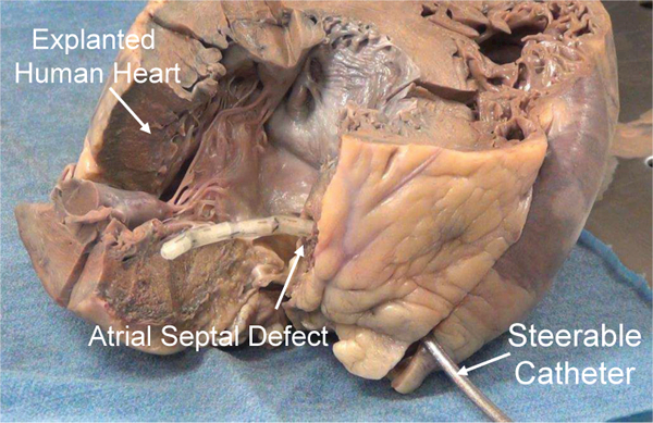
An SMA actuated cardiac catheter through an artificial atrial septal defect steered within the left atrium.
II. System Design and Fabrication
The developed catheter is comprised of a flexible stem and a steerable tip covered by an elastomeric sleeve fabricated by a 3D printer, as shown in Fig. 2. The flexible stem is a 9 French outer diameter braid reinforced tubing with high flexibility and kink resistance (Duke Extrusion, Santa Cruz, California, USA). The steerable tip is composed of multiple bending modules, as shown in Fig. 3(a). Each bending module is comprised of a pair of 190 μm diameter SMA wires bonded between two rigid module links, as shown in Figs. 3(b) to (d). Each link has an outer diameter of 2.9 mm and a through channel of 1.3 mm diameter. Since the two SMA wires bend antagonistically, the bending module can be bidirectionally actuated by individually heating each SAM wire. When two bending modules are directly assembled together via protrusions and recesses on adjacent module links, these two modules bend in two orthogonal directions, as shown in Fig. 3(b). If a positive adapter is utilized, the length of the steerable tip can be adjusted, as shown in Fig. 3(c). If a negative adapter is assembled between two bending modules, these two modules can bend in a parallel direction, as shown in Fig. 3(d).
Fig. 2.
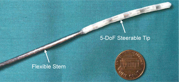
A developed cardiac catheter prototype comprised of a flexible stem and a steerable tip.
Fig. 3.
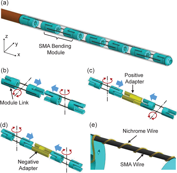
3D models of the catheter tip: (a) steerable tip comprised of multiple bending modules, (b) assembly of two bending modules with orthogonal bending directions, (c) assembly of two bending modules via a positive adapter, (d) assembly of two bending modules via a negative adapter, and (e) Nichrome coils routed around an SMA wire of a bending module. The red arrows show bending directions and the blue arrows show assembly directions.
To develop an MRI-compatible catheter, the technqiue of conductive heating actuation is developed. As shown in Fig. 3(e), a high-resistivity 30 μm diameter Nichrome wire is tightly routed around the bending segment of the SMA wire to fonn Nichrome coils. By applying electric current to the Nichrome coils, the Nichrome coils will be heated by Joule heating and the temperature of the SMA wire wrapped within the Nichrome coils will increase due to conductive heat transfer between the Nichrome coils and the SMA wire. Due to the high resistivity and small cross-section area of the Nichrome wire, the electric current required for Joule heating is very low. Therefore, ultra-thin enameled magnet wires (44 AWG) can be soldered to the Nichrome coils and then connected to a power supply. As a result, there is significant free space inside the catheter channel to pass through surgical tools when multiple SMA bending modules are integrated to form a multi-DoF steerable tip. The SMA training procedure is the same as that in our previous work for 0.5 mm diameter SMA wires [13] and the memorized configuration is 90° for a curvature of 0.67 mm-1.
A set of jigs are designed and 3D printed to route the Nichrome wire around the bending segment of the SMA wire, as shown in Fig 4(a). Both the upper frame and the lower frame contain an array of teeth with a groove along its axis. When they are assembled face to face, the space between teeth form a helical routing path with a pitch of 800 μm and a channel goes through the center. To route the Nichrome wire as shown in Fig. 3(e), the straight segment at one end of the SMA wire is fixed inside the groove of the base frame by using the fixture, a bolt, and a nut. By manually straightening the bending segment using a plier, the straight segment at the other end of the SMA wire is fixed in the same way. Afterwards, the upper frame and lower frame are fixed onto the base frame, so that the bending segment of the SMA wire is constrained inside the channel between the two frames. Meanwhile, a Nichrome wire is folded into two strands and tied onto the tip of a 90 μm diameter superelastic wire at the folding point. After taping the two ends of the Nichrome wire on the base frame, the superelastic wire with the Nichrome wire is repeatedly passed through the space between adjacent teeth and routed around the SMA wire along the helical path. Sufficient pulling force should be applied to the superelastic wire once it passes through the teeth each time, so that a series of Nichrome coils are tightly wrapped around the SMA wire. In the end, the upper frame and lower frame are removed and super glue is applied to fix the Nichrome coils on the SMA wire.
Fig. 4.

3D models showing the fabrication procedure of the SMA bending module: (a) fixing an SMA wire onto the jigs before routing a Nichrome wire, (b) assembling two SMA wires to a module link, and (c) connecting the module link with SMA wires to another link. The blue arrows indicate assembly directions.
To assemble two SMA wires with Nichrome coils onto two module links in an antagonistic configuration, two sets of assembly jigs are developed. As shown in Fig. 4(b), a module link is fixed between a base frame and a coupler. The grooves of the link for fixing two SMA wires face upward and downward, respectively, by matching the protrusions of the link to the recess of the coupler. Meanwhile, the SMA wires are heated by a heat gun to return to the memorized curved configurations. By fitting the straight segment at one end of the SMA wire into the link groove, pressing the upper frame and lower frame into the flat recess of the base frame, and applying epoxy adhesive to the grooves, the two SMA wires can be fixed onto the link in an antagonistic configuration. After removing the module link from the base frame in Fig. 4(b), the bending segments of the two SMA wires are manually straightened and the module link is then assembled to a coupler, as shown in Fig. 4(c). Afterwards, the left frame and right frame are assembled together with the coupler to make the SMA wires fit into the grooves formed between the two frames. After assembling the other module link and the other coupler, and pressing the SMA wires into the grooves of the module link, epoxy adhesive is applied to fix the SMA wires. The fabrication is completed by removing the jig sets after the adhesive dries.
III. Actuator Modeling
A. Electromagnetic Field
When electric current is applied to a metallic wire, such as an SMA wire or a Nichrome wire, the magnetic field at a spatial point is given by [21]:
| (1) |
where r, r’, J, t, and c are a point in the world space, a point along the current flow, current density, time, and speed of light. tr is the retarded time and it is given by: Eq. (1) indicates that the magnetic field is caused by the current density and current density variation. When the SMA actuated catheter is manipulated within a cardiovascular system under intra-operative MRI guidance, the distance from the region of interest (ROI) to the steerable tip is within several centimeters. When the current density is modulated by a control system, we have:
| (2) |
where ts is the time step for the control system. From Eqs. (1) and (2), the magnetic field generated by the current density variation is much smaller than that induced by the current density and can be thereby neglected in modeling. Thus, for a metallic wire under intrinsic Joule heating, the magnetic field magnitude around it is given by: , where μ0, I, and d are the permeability of free space, electric current magnitude, and the shortest distance to the SMA wire from a spatial point. Preliminary tests showed about 2 A current is required to actuate a bending module under intrinsic Joule heating actuation in water at room temperature. However, the same bending module with Nichrome coils under conductive heating actuation requires much lower current, which will be presented in the next section. Meanwhile, the Nichrome coils work as a solenoid and thereby generate negligible magnetic field outside the SMA wire. Since the Nichrome coils are formed from a folded Nichrome wire, electric current flows are opposite to each other in the two parallel subsets of coils and the induced magnetic fields cancel each other, leading to the further reduce of the magnetic field.
B. Heat Transfer
To model an SMA wire with Nichrome coils under conductive heating actuation, a few assumptions are made: a) Temperature of the Nichrome coils and SMA wire is individually homogeneous; b) Heat is dissipated into air through free convection at room temperature; c) The thermal effect of super glue is negligible due to its tiny volume. The length of the Nichrome wire around an SMA wire of unit length, lr, is given by where pr and ds are the pitch of the Nichrome coils and SMA wire diameter, respectively. The heat generated on the Nichrome coils is transferred to the SMA wire via contact conductance in addition to raising the Nichrome wire temperature and the dissipation into air. Thus, the heat transfer model for Nichrome coils is given by:
| (3) |
where Tr, Ta, ha, dr, pr, Cr, βr, I, Ts, and hc are the temperature of Nichrome coils, air temperature, heat convection coefficient for free air, Nichrome wire diameter, Nichrome density, specific heat capacity of Nichrome, Nichrome resistivity, heating current, SMA wire temperature, and the coefficient of thermal contact conductance, respectively. The heat transferred to the SMA wire via contact conductance increases the SMA wire temperature and induces SMA phase transformation in addition to the dissipation into air [22]—[24]. By assuming the contact area between the Nichrome coils and the SMA wire of a unit length is equal to 2lrdr, the heat transfer model for the SMA wire is given by:
| (4) |
where ps, Cs, Ls, and ξ are the SMA density, specific heat capacity of SMA, latent heat of phase transformation, and martensite volume fraction of SMA, respectively. The value of hc depends on the contact force between the SMA wire and Nichrome coils, and is influenced by the applied super glue. Therefore, it will be estimated in the following section.
C. SMA Constitutive Model
Since Liang and Roger’s model has been commonly used for SMA actuator modeling [13], [25], it is used in this work to model the thermomechanical properties of the SMA bending module. As the strain change induced by thermal expansion is negligible, the SMA constitutive model is given by [26]:
| (5) |
where σ, e, E, and ϵL are the SMA stress, strain, Young’s modulus, and maximum recoverable strain, respectively. The subscript ‘0’ denotes the initial condition. E is given by: , where EM and EA are the Young’s modulus values in the austenite (A) and martensite (M) state, respectively. The martensite volume fraction, ξ, during SMA heating is given by:
| (6) |
where As and Af are the transformation start and finish temperatures for the heating process, respectively. CA is the stress influence coefficient.
IV. Experimental Studies
A. Fatigue Tests
To evaluate the working performance of the SMA bending module and the reliability of the super glue as a bonding layer between the SMA wire and Nichrome coils, a series of fatigue tests are conducted. As shown in Fig. 5(a), one link of a bending module is fixed onto a fixture with two vision markers and a moving link with another two vision markers is fixed onto the other module link. Meanwhile, a stereoscopic camera (MicronTracker H40, Toronto, Ontario, Canada) is used to track the position of the four vision markers to compute the bending angle of the bending module. By alternately applying 40 mA current for 5 s to the Nichrome coils around the upper SMA wire and the lower SMA wire with a natural cooling interval of 30 s between two heating periods, the bending module is bi-directionally actuated for repeated cycles. A stereo microscope (Model S6D, Leica, Wetzlar, Germany) is employed to examine the SMA wire with Nichrome coils after every 25 cycles. It is observed that Nichrome coils are still tightly bonded with the SMA wire after 200 cycles, as shown in Figs. 5(b) and (c). These tests have demonstrated that super glue can be employed as a reliable bonding agent between the SMA wire and Nichrome coils, due to the high service temperature up to 82°C and flexibility of the super glue.
Fig. 5.
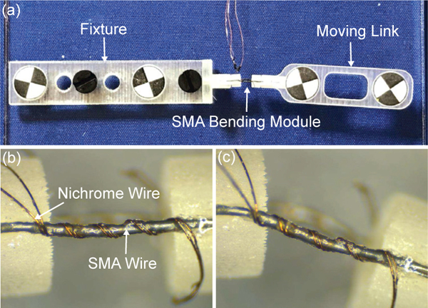
(a) A setup for carrying out the fatigue tests for the SMA bending module. Microscopic photo of the SMA wire with Nichrome coils before actuation (b) and after bi-directional bending of 200 cycles (c).
Fig. 6(a) shows the maximum bending angles with respect to bending cycles at 40 mA current. The maximum bending angles decrease significantly in the first 50 cycles and converge to a stable value of about 33° and 35.5° for the lower and upper SMA wire, respectively. This is primarily due to the change of the SMA thermomechanical behavior during cyclic loading [27]. The cyclic loading causes an accumulation of dislocations around defects in SMA microstructure, which results in an increase of residual martensite volume fraction and a decrease of stress during forward phase transformation (M → A). It is also observed that the bending module twists when it bends. To define the twist angle, the vision markers on the moving link are projected to the plane perpendicular to the vector through the vision markers on the fixture. The twist angle is the angle between the horizontal plane and the vector through the two projection points. Fig. 6(b) shows the twist angles of the bending module with respect to the bending angles. Since the straight configuration is a geometric singularity for computing the twist angle, the computation of the twist angle when the bending angle is close to 0 has a large error due to the limited tracking precision of the stereoscopic camera. Thus, the twist angles for the bending angle from - 10° to 10° are not shown. It is observed that the average twist angle is about 11.4° and 6.7° for the negative (upper SMA wire) and positive bending (lower SMA wire), respectively. In addition to the moment arm from the bending force to the link axis, the twisting is probably caused by imperfect alignment of SMA wires during fabrication.
Fig. 6.
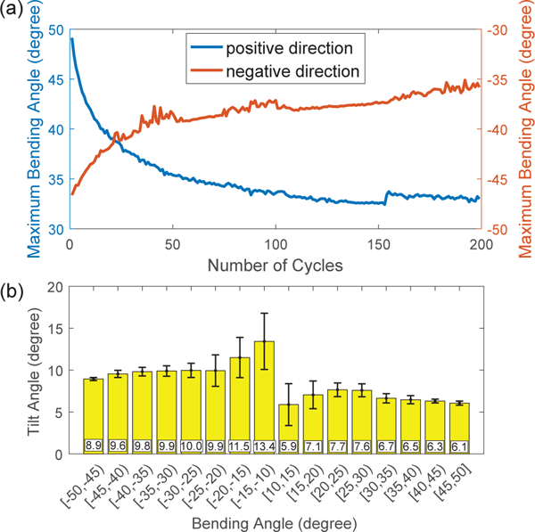
Experimental results of fatigue tests: (a) change of the maximum bending angles in terms of bending cycles and (b) change of the twist angles of the bending module in terms of bending angles.
B. SMA Actuation Comparison
In the second series of tests, the heating and cooling speed of SMA wires under conductive heating actuation by Nichrome coils are compared with the same SMA wires under intrinsic Joule heating actuation. The experimental setup is shown in Fig. 7(a). After the bending module is manually set at a straight configuration, one link of the bending module is fixed onto a fixture and the other link is bonded with an adapter with a conic tip on the side contacting a load cell. When the SMA wire is thermally actuated, the recovery motion of the SMA wire is blocked by the load cell and the block force can be measured. In the first case, electric current from 10 mA to 20 mA with a step of 5 mA and from 20 mA to 38 mA with a step of 2 mA is applied to the Nichrome coils around the SMA wire for 40s, followed by 40s natural cooling. In the second case, electric current from 0.1 A to 0.9 A with a step of 0.1 A is applied to the SMA wire for intrinsic Joule heating actuation for 40 s, followed by 40 s natural cooling. Each test was repeated three times. Figs. 7(b) and (c) show the change of the block force for these two cases at several typical current levels. It is observed that the electric current required for conductive heating actuation is about 20% of that required for intrinsic Joule heating actuation to achieve the same level of stable block force.
Fig. 7.
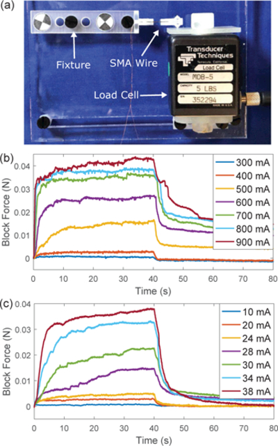
Comparison between Joule heating actuation and conductive heating actuation: (a) experimental setup to measure the block force of the SMA wire, (b) block force of the SMA wire under Joule heating actuation, and (c) block force of the SMA wire under conductive heating actuation.
By defining the time required to achieve 63% of the maximum force increase during heating and 63% of the maximum force drop during cooling as the heating time and cooling time, respectively, the average heating time and cooling time with standard deviations for four groups of stable block force are shown in Figs. 8(a) and (b). It is observed that the conductive heating actuation requires more heating time, probably due to the large Nichrome coil pitch in the current design. Since the electric current required for the conductive heating actuation is much smaller, the heating response can be improved by increasing the electric current. The cooling time for the conductive heating actuation is slightly longer than that for the intrinsic Joule heating actuation, probably due to the larger heat capacity of the SMA wire with Nichrome coils and the impediment of natural convection by super glue.
Fig. 8.
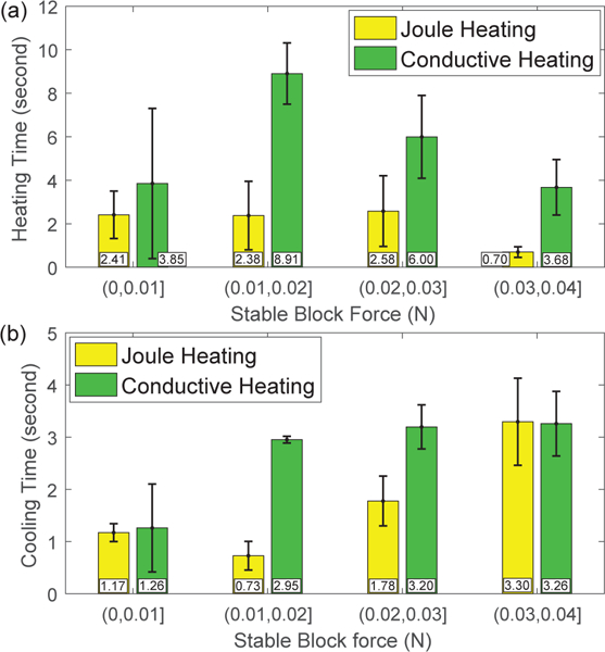
Comparison of heating response (a) and natural cooling response (b) for an SMA bending module between Joule heating actuation and conductive heating actuation.
C. MRI-Compatibility Evaluation
The MRI-compatibility of the developed steerable tip is evaluated and the experimental setup is shown in Fig. 9(a). The braid reinforced tube is removed due to its stainless steel braids, while the steerable tip is fixed on a 3D printed plastic tube and the distal two bending modules are immersed inside water in a container. The experimental setup was placed inside a 60 mm diameter quadrature detection coil (Doty Scientific Inc., Columbia, SC) within a 7 Tesla MRI scanner (PharmaScan®, Bruker, Billerica, MA) to acquire MR images. The repetition time (TR) and echo time (TE) are 50 ms and 2.6 ms, respectively. In the first case, the second distal bending module of the steerable tip is actuated by intrinsic Joule heating actuation. Figs. 10(a) and (b) show the MR images acquired before actuation and when 2 A current is applied for 10 s. It is observed that a strong artifact is generated near the tip boundary due to the large electric current. The bending angle is relatively small due to fast heat dissipation into water. In the second case, the second distal bending module is actuated by conductive heating. Figs. 10(c) to (f) show that there are no observable artifacts when the steerable tip is actuated by 100 mA electric current. Fig. 9(b) concludes the signal-to-noise ratio (SNR) values of MR images acquired before, during, and after actuation for three individual tests. It is observed that the SNR values were almost constant in the whole procedure. The difference between these two cases proves that large electric current causes strong electromagnetic field and the developed steerable tip is MRI-compatible due to its small electric current requirement. To calculate SNR values, two consecutive images with 5 s interval are acquired when the catheter is maintained at the same posture. After selecting a fixed ROI as shown in Figs. 10(c) to (f), the mean pixel intensity within the ROI in the first image is defined as the image signal. A third image is obtained by subtracting the second one from the first one and the image noise is defined as the standard deviation of the pixel intensity within the same ROI in the third image divided by √2 [28]. To develop a fully MRI-compatible catheter, the braid reinforced tube can be customized to use nitinol as the filament material.
Fig. 9.
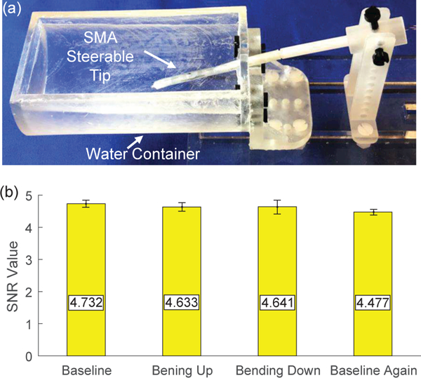
MRI-compatibility evaluation: (a) experimental setup including an SMA steerable tip placed inside a water container and (b) SNR values of MR images acquired before actuation (baseline), when the tip moves upward and downward, and after actuation (baseline again).
Fig. 10.
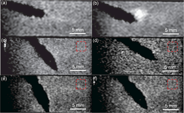
MR image of an SMA actuated catheter tip under intrinsic Joule heating actuation before actuation (a) and during actuation (b). MR image of an SMA actuated catheter tip with Nichrome coils under the conductive heating actuation before actuation (c), when the tip moves upward (d) and downward (e), and after the power is turned off (f).
D. Estimation of Contact Conductance Coefficient
Since the SMA wire training method is the same as our previous work [13], the parameter values of the SMA constitutive model are taken from our previous work and listed in Table I with geometric parameters. For the heat transfer model, the value of heat convection coefficient for free air, ha, is approximately equal to 5 W/(m2K) [29]. To estimate the conductance coefficient between the SMA wire and Nichrome coils, hc, an experiment is performed. The experimental setup is similar to Fig. 5(a), except that the bending module is only equipped by one SMA wire with Nichrome coils. The bending module is heated by a heat gun to return to the maximum bending angle which is measured by the stereoscopic camera. Afterwards, the bending module is manually deformed to the straight configuration. By applying electric current to the Nichrome coils for 20 s at different current levels, the SMA wire bends to a stable angle at each current level and undergoes stepwise shape recovery towards the maximum bending angle. The current increases from 0 to 20 mA at a step of 5 mA and from 20 mA to 40 mA at a step of 2 mA. Fig. 11 shows the average angular recovery percentage with respect to current magnitude for three individual tests, computed from the initial bending angle (θ0), maximum bending angle (θm), and the stable bending angle (θi) at each current level. Since the SMA stress is zero, Eq. (5) can be simplified into: ϵ = ϵ0ξ. Since the length of the bending segment of the SMA wire is constant, we have:.At each stable bending angle, it is assumed that the SMA wire and Nichrome coils are in the quasi-static status, so the quasi-static models can be obtained from Eqs. (3) and (4) and then combined with the SMA constitutive model to estimate the value of hc using the least squares regression. The estimated value of hc is listed in Table I. Fig. 11(a) shows the model prediction based on the estimation result. The root-mean-square error and R-squared value between the experimental results and model prediction are 0.0704 and 0.9775, respectively. The estimated value of hc is relatively small, because there is a glue layer between the SMA wire and Nichrome coils, and the actual contact area is smaller than the assumption made for Eq. (4). Overall, the model has successfully captured the thermomechanical properties of the SMA bending module and the model can be potentially used for design optimization and model-based control in the future.
TABLE I.
Properties of the SMA wire and Nichrome wire
| variable | value | unit | variable | value | unit |
|---|---|---|---|---|---|
| dr | 0.03 | mm | As | 31.5 | °C |
| ds | 0.19 | mm | Af | 64.5 | °C |
| pr | 0.8 | mm | CA | 30 | MPa/°C |
| ha | 5 | W/(m2·K) | hc | 0.34 | W/(m2·K) |
Fig. 11.
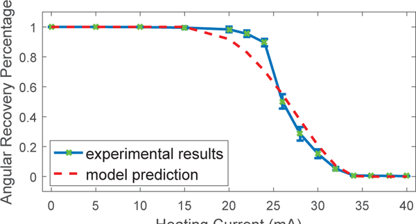
Angular recovery percentage of the SMA wire at different electric current to the Nichrome coils compared with model prediction. The root-mean-square error and R-squared value between the experimental results and model prediction are 0.0704 and 0.9775, respectively.
E. Proof-of-Concept Demonstration
To evaluate the working performance of the developed cardiac catheter with an SMA actuated steerable tip, a catheter prototype was inserted into the right atrium through the inferior vena cava for a proof-of-concept demonstration, as shown in Fig. 12. When the catheter tip was actuated, its motion can be viewed via a viewing channel through the superior vena cava. The initial posture of the catheter tip is shown in Fig. 12(b). Afterwards, 50 mA current under pulse width modulation (PWM) was applied to individually actuate the first two distal bending modules and the PWM intensity was controlled by an operator via a keyboard. Figs. 12(c) and (d) show the tip moving upward and downward, respectively, by actuating the first distal bending module. In this procedure, the PWM intensity was increased from 0 to 100% and then decreased to 0 for the Nichrome coils responsible for bending the tip upward, followed by the increase of PWM intensity from 0 to 100% for the Nichrome coils responsible for bending the tip downward. While keeping the tip downward, the second distal bending module was actuated to bend the tip leftward and rightward, as shown in Figs. 12(e) and (f), respectively.
Fig. 12.
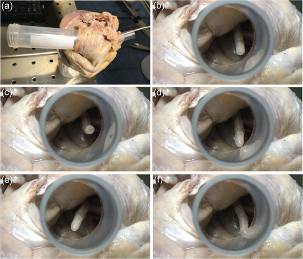
A steerable catheter prototype inserted into the right atrium through the inferior vena cava and viewed from the superior inferior vena cava (a). The steerable tip before actuation (b), moving upward (c) and downward (d) by actuating the first distal bending module, and moving leftward (e) and rightward (f) by actuating the second distal bending module.
V. DISCUSSION AND CONCLUSIONS
In this paper, we have presented the development of a steerable and MRI-compatible cardiac catheter using SMA actuators for AFib treatment. The catheter tip is composed of multiple bending modules and each module is actuated by a pair of antagonistic SMA wires. To improve the MRI- compatibility and reduce the electric current required for SMA actuation, a conductive heating actuation technique has been developed by routing Nichrome coils around SMA wires using customized jigs. After modeling the SMA bending module, the experimental results of working performance evaluation and a proof-of-concept demonstration have shown the potential of using the developed catheter as an alternative tool for the treatment of AFib. Although the maximum bending angle of the SMA bending module decreases when it performs cyclic motion, it will not be an issue if feedback control is implemented and reference angles are smaller than the stable maximum bending angle. Since high-speed motion is usually not required in cardiac surgery, the relatively slow response of SMA actuators will not be an issue. In addition, the actuation speed can be improved by adjusting the electric current under feedback control, and the cooling response can be potentially improved by using forced fluidic cooling [30].
For the future works, we are planning to develop proprioceptive bending sensors based on fiber Bragg grating (FBG) strain sensing to realize feedback control of the SMA bending modules. The bending sensors are required to be flexible, so that the resistive force applied to the SMA bending module can be minimized. The twist of the SMA bending module when it is activated will be reduced by improving the design of the bending module and fabrication jigs. Diagnostic and therapeutic tools, such as an optical camera and ablation electrodes, will be integrated for future ex vivo studies.
Acknowledgments
This paper was recommended for publication by Editor Ken Masamune upon evaluation of the Associate Editor and Reviewers’ comments. *This work was supported by the National Institute of Biomedical Imaging and Bioengineering of the National Institutes of Health under Award Number R21EB019161. The content is solely the responsibility of the authors and does not necessarily represent the official views of the National Institutes of Health.
References
- [1].Colilla S, Crow A, Petkun W, Singer DE, Simon T, and Liu X, “Estimates of current and future incidence and prevalence of atrial fibrillation in the US adult population,” The American Journal of cardiology, vol. 112, no. 8, pp. 1142–1147, 2013. [DOI] [PubMed] [Google Scholar]
- [2].Chard M and Tabrizchi R, “The role of pulmonary veins in atrial fibrillation: a complex yet simple story,” Pharmacology & Therapeutics, vol. 124, no. 2, pp. 207–218, 2009. [DOI] [PubMed] [Google Scholar]
- [3].Pappone C, Rosanio S, Oreto G, Tocchi M, Gugliotta F, Vice- domini G, Salvati A, Dicandia C, Mazzone P, Santinelli V, et al. , “Circumferential radiofrequency ablation of pulmonary vein ostia a new anatomic approach for curing atrial fibrillation,” Circulation, vol. 102, no. 21, pp. 2619–2628, 2000. [DOI] [PubMed] [Google Scholar]
- [4].Jaїs P, Weerasooriya R, Shah DC, Hocini M, Macle L, Choi K-J, Scavee C, Haїssaguerre M, and Clémenty J, “Ablation therapy for atrial fibrillation (AF),” Cardiovascular Research, vol. 54, no. 2, pp. 337–346, 2002. [DOI] [PubMed] [Google Scholar]
- [5].Kesner SB and Howe RD, “Design and control of motion compensation cardiac catheters,” in Robotics and Automation (ICRA), 2010 IEEE International Conference on. IEEE, 2010, pp. 1059–1065. [DOI] [PMC free article] [PubMed] [Google Scholar]
- [6].Rafii-Tari H, Payne CJ, and Yang G-Z, “Current and emerging robot- assisted endovascular catheterization technologies: a review,” Annals of biomedical engineering, vol. 42, no. 4, pp. 697–715, 2014. [DOI] [PubMed] [Google Scholar]
- [7].Park K-T and Esashi M, “A multilink active catheter with polyimide- based integrated CMOS interface circuits,” Journal of Microelectromechanical Systems, vol. 8, no. 4, pp. 349–357, 1999. [Google Scholar]
- [8].Mineta T, Mitsui T, Watanabe Y, Kobayashi S, Haga Y, and Esashi M, “Batch fabricated flat meandering shape memory alloy actuator for active catheter,” Sensors and Actuators A: Physical, vol. 88, no. 2, pp. 112–120, 2001. [Google Scholar]
- [9].Mineta T, Mitsui T, Watanabe Y, Kobayashi S, Haga Y, and Esashi M, “An active guide wire with shape memory alloy bending actuator fabricated by room temperature process,” Sensors and Actuators A: Physical, vol. 97, pp. 632–637, 2002. [Google Scholar]
- [10].Tung AT, Park B-H, Koolwal A, Nelson B, Niemeyer G, and Liang D, “Design and fabrication of tubular shape memory alloy actuators for active catheters,” in Biomedical Robotics and Biomecha- tronics, 2006. BioRob 2006. The First IEEE/RAS-EMBS International Conference on. IEEE, 2006, pp. 775–780. [Google Scholar]
- [11].Abadie J, Chaillet N, and Lexcellent C, “Modeling of a new SMA micro-actuator for active endoscopy applications,” Mechatronics, vol. 19, no. 4, pp. 437–442, 2009. [Google Scholar]
- [12].Shim J-E, Quan Y-J, Wang W, Rodrigue H, Song S-H, and Ahn SH, “A smart soft actuator using a single shape memory alloy for twisting actuation,” Smart Materials and Structures, vol. 24, no. 12, p. 125033, 2015. [Google Scholar]
- [13].Ayvali E, Liang C-P, Ho M, Chen Y, and Desai JP, “Towards a discretely actuated steerable cannula for diagnostic and therapeutic procedures,” The International Journal of Robotics Research, vol. 31, no. 5, pp. 588–603, 2012. [DOI] [PMC free article] [PubMed] [Google Scholar]
- [14].Beinart R and Nazarian S, “Role of magnetic resonance imaging in atrial fibrillation ablation,” Current Treatment Options in Cardiovascular Medicine, vol. 16, no. 6, p. 316, 2014. [DOI] [PMC free article] [PubMed] [Google Scholar]
- [15].Higuchi K, Akkaya M, Akoum N, and Marrouche NF, “Cardiac MRI assessment of atrial fibrosis in atrial fibrillation: implications for diagnosis and therapy,” Heart, vol. 100, no. 7, pp. 590–596, 2014. [DOI] [PubMed] [Google Scholar]
- [16].Ryu SC, Quek ZF, Koh J-S, Renaud P, Black RJ, Moslehi B, Daniel BL, Cho K-J, and Cutkosky MR, “Design of an optically controlled MR-compatible active needle,” IEEE Transactions on Robotics, vol. 31, no. 1, pp. 1–11, 2015. [DOI] [PMC free article] [PubMed] [Google Scholar]
- [17].Oishi R, Yoshida H, Nagai H, Xu Y, and Jang B-K, “Smart composite material system with sensor, actuator, and processor functions: a model of holding and releasing a ball,” in SPIE’s 9th Annual International Symposium on Smart Structures and Materials. International Society for Optics and Photonics, 2002, pp. 326–333. [Google Scholar]
- [18].Paik JK and Wood RJ, “A bidirectional shape memory alloy folding actuator,” Smart Materials and Structures, vol. 21, no. 6, p. 065013, 2012. [Google Scholar]
- [19].Knopf GK, “Optically driven shape memory alloy microactuators,” in Proc. of SPIE Vol, vol. 5263, 2004, p. 23. [Google Scholar]
- [20].Ryu SC, Renaud P, Black RJ, Daniel BL, and Cutkosky MR, “Feasibility study of an optically actuated MR-compatible active needle,” in Intelligent Robots and Systems (IROS), 2011 IEEE/RSJ International Conference on. IEEE, 2011, pp. 2564–2569. [DOI] [PMC free article] [PubMed] [Google Scholar]
- [21].Griffiths D, Introduction to Electrodynamics. Pearson Education, 2014[Online]. Available: https://books.google.com/books?id=J9ygBwAAQBAJ
- [22].Cheng SS and Desai JP, “Towards high frequency actuation of SMA spring for the neurosurgical robot-MINIR-Ii,” in Robotics and Automation (ICRA), 2015 IEEE International Conference on. IEEE, 2015, pp. 2580–2585. [Google Scholar]
- [23].Armattoe KM, Bouby C, Haboussi M, and Zineb TB, “Modeling of latent heat effects on phase transformation in shape memory alloy thin structures,” International Journal of Solids and Structures, vol. 88, pp. 283–295, 2016. [Google Scholar]
- [24].Cheng SS, Kim Y, and Desai JP, “New actuation mechanism for actively cooled SMA springs in a neurosurgical robot,” IEEE Transactions on Robotics, 2017. [DOI] [PMC free article] [PubMed] [Google Scholar]
- [25].Sheng J and Desai JP, “Design, modeling and characterization of a novel meso-scale SMA-actuated torsion actuator,” Smart Materials and Structures, vol. 24, no. 10, p. 105005, 2015. [DOI] [PMC free article] [PubMed] [Google Scholar]
- [26].Liang C and Rogers C, “One-dimensional thermomechanical constitutive relations for shape memory materials,” Journal of Intelligent Material Systems and Structures, vol. 1, no. 2, pp. 207–234, 1990. [Google Scholar]
- [27].Jesse Lim T and McDowell DL, “Path dependence of shape memory alloys during cyclic loading,” Journal of Intelligent Material Systems and Structures, vol. 6, no. 6, pp. 817–830, 1995. [Google Scholar]
- [28].N. E. M. Association et al. , “Determination of signal-to-noise ratio (SNR) in diagnostic magnetic resonance imaging,” NEMA Sandards Publication MS 1–2001, 2001. [Google Scholar]
- [29].Whitelaw JH, “Convective heat transfer,” p. 237, 1997. [Google Scholar]
- [30].Gafford JB, Wood RJ, and Walsh CJ, “A high-force, high- stroke distal robotic add-on for endoscopy ,” in Robotics and Automation (ICRA), 2017 IEEE International Conference on. IEEE, 2017, pp. 1117–1124. [Google Scholar]


