Abstract
In the context of structural heart disease, ventricular tachycardia (VT) is related to surviving fibres in incomplete scar. New technologies which allow electroanatomic mapping at higher density and with smaller, more closely spaced electrodes have allowed new insights into the characteristics of VT circuits. VT isthmuses are complex structures, with multiple entrances, exits and dead ends of activation. The isthmus is frequently defined by regions of functional block and several VT circuits can be possible in a VT “critical zone”. In this review, we discuss these new insights and how they may improve VT ablation strategies, as well as discussing emerging technologies which may further develop our understanding.
Keywords: VT, ablation, substrate mapping, catheters, arrhythmia
Ventricular tachycardia (VT) in the context of structural heart disease is related to patchy or incomplete scar; usually arising from re-entrant circuits which are dependent on surviving channels of activation through scar tissue.[1–3] These protected isthmuses are critical for maintaining VT, and an improved understanding of the characteristics of VT isthmuses is important in guiding strategies for VT ablation. VT isthmuses are often unmappable in clinical practice due to non-inducibility, multiple inducible VTs which interrupt the mapping process, and haemodynamic instability during VT.[4,5]
Historical Data
It has long been known that scar-related VT is dependent on poorly-coupled surviving fibres in scarred areas. Early catheter mapping studies identified complex signals with decremental conduction delay which were mid-diastolic during tachycardia.[6] Mapping with electrode arrays during surgical ablation of post-infarction VT also identified poorly-coupled signals in areas of dense scar, further demonstrating that these signals were endocardial in origin and separated by dense scar tissue from surviving epicardial myocardium (Figure 1).[7]
Figure 1: Endocardial Scar Substrate After MI.
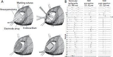
A: Recordings were made with a multielectrode array before and after resection of endocardial scar. B: VT recordings identify mid-diastolic signals in dense scar (arrows point to signals.). In sinus rhythm, there are corresponding LAVA signals late after the local far-field electrogram (arrows). After resection of the endocardial scar, the LAVAs are no longer present and VT is non-inducible. CL = cycle length; LAVA = local abnormal ventricular activity NSR = normal sinus rhythm; VT = ventricular tachycardia. Source: Miller et al.[7] Reproduced with permission from Wolters Kluwer Health.
More complex mapping of VT circuits with entrainment manoeuvres to identify concealed entrainment, post-pacing intervals and stimulus-QRS times as well as electrogram (EGM) characteristics, identified the existence of more complex elements of the VT circuit. This included inner and outer loops, a common isthmus and bystander loops or dead ends of activation (Figure 2).[8] These techniques are, however, relatively time-consuming because gathering information at each individual point requires entrainment (without terminating the tachycardia) and measurement of intervals. This limits the maximal spatial resolution of the technique and does not allow determination of the anatomical characterisation of the key parts of the VT circuit.
Figure 2: Components of the Ventricular Tachycardia Circuit Identified by Pacing and Entrainment Manoeuvres.
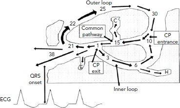
The key components of the VT circuit are identified: the common pathway, outer loop, inner loop through scar tissue, and dead-end activation (C, E, H). Pacing manoeuvres allow identification of these sites in principle, but use in routine mapping of VTs is limited by the stability of the VT and the time taken to pace at multiple sites. CP = common pathway; VT = ventricular tachycardia. Source: Stevenson et al. 1993.8 Reproduced with permission from Wolters Kluwer Health.
Early electroanatomic mapping systems were used to identify VT circuits with a greater degree of spatial accuracy. This allowed identification of the key characteristics of VT circuits, with identification of typical isthmus orientation and position in post-infarct VTs.[1,3] The limited number of recorded points and relatively large sensing bipole used when mapping with an ablation catheter limited the ability of these studies to define the characteristics of VT isthmuses more clearly. Consequently, understanding of the isthmus was limited to site and general orientation, rather than an understanding of more complex details, such as position within the scar, morphology, conduction velocities, and the role of functional and complete block.
High-density Mapping
Electroanatomic mapping systems and multipolar mapping systems have been developed which allow collection of greater numbers of EGM from smaller, more closely spaced electrodes (Table 1).[9] One of the primary limitations of the techniques described above is that the EGMs were often recorded with a large electrode surface area, particularly in the case of a 3.5 mm ablation catheter tip and relatively large bipolar spacing. Human mapping studies performed with multipolar catheters have clearly demonstrated the effect of increasing bipole distance on the relative sizes of near- and far-field EGMs with clear implications for the ability of human observers and machine algorithms to differentiate the two (Figure 3).[10,11] This work has been developed further using the Advisor™ HD Grid mapping catheter (Abbott) in sheep, demonstrating that near-field signals from poorly coupled abnormal fibres are largely unaffected by bipole spacing (as long as the fibre lies between the two poles) but that far-field signals are significantly lessened by reducing the bipole spacing, thereby improving near-field detection.[12]
Table 1: Comparison of Commonly Used High-density Electroanatomical Mapping Systems and Catheters.
| System | Localisation Technology | Typical Number of Points/Map | Mapping Catheter | Electrodes | Electrode Spacing |
|---|---|---|---|---|---|
| EnSite Precision (Abbott Vascular) | Magnetic and impedance | Thousands | HD Grid | 16 × 1 mm ring electrodes | 3-3-3 mm on four spines 3 mm apart in planar formation |
| Livewire Duo-Decapolar | 20 × 1 mm ring electrodes | 2-2-2 or 2-5-2 mm on a single catheter | |||
| CARTO 3 (Biosense Webster) | Magnetic and impedance | Thousands | PentaRay | 20 × 1 mm ring electrodes | 2-5-2 or 4-4-4 mm on five radiating spines |
| Lasso | 10 or 20 × 1 mm ring electrodes | 4.5, 6 or 8 mm on a circular spine | |||
| DecaNav | 10 × 1 mm ring electrodes | 2-8-2 mm on a single catheter | |||
| Rhythmia (Boston Scientific) | Magnetic and impedance | Thousands to tens of thousands | Orion | 64 × 0.4 mm2 patch electrodes | 2.5 mm on eight spines of a collapsible mini basket |
Figure 3: The Impact of Electrode Characteristics on Electrogram Recordings.
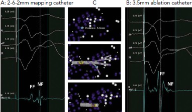
A: Electrograms recorded with a dedicated mapping catheter. Clearly separated near-field and far-field components are visible. B: Electrograms recorded at the same site (0.6 mm separation) with a 3.5 mm ablation catheter. The near-field component is almost completely obscured by the much larger far-field component. C: A 3D mapping system demonstrating the relative positions of the electrograms recorded. Electrode orientation is similar with each catheter. FF = far-field; NF = near-field. Source: Berte et al.[10] Reproduced with permission from John Wiley and Sons.
A second major limitation of these studies is that the resolution of the mapping techniques is not fine enough to determine the properties of the VT isthmus in detail. A microelectrode study (on a scale of 100 μm) of excised infarcted human papillary muscles identified complex activation patterns in a thin layer of surviving endocardial fibres overlying a densely infarcted zone. Slow conduction in these fibres was the result of activation at near normal speeds on a microscopic level following a zig-zag course through poorly coupled fibres, resulting in overall slowing of conduction.[13] Close bipolar spacing is also helpful in this regard, in that the position of the EGM is more accurately determined as signals are recorded from a smaller volume.
The other significant improvement of modern mapping systems lies in the number of EGMs that can be collected, stored and analysed by multipolar recording catheters and improved software. The increase from tens of EGMs in the initial studies to tens of thousands with modern systems has resulted in several major improvements. The resolution of the maps generated has significantly improved. The time taken to generate a map has reduced as multipolar catheters record from areas of myocardium, rather than single points, allowing rapid collection of points over a large area.[14,15] By collecting multiple EGMs at each location, outlier signals arising from ectopy, noise or catheter instability can be excluded, improving the quality of the signals recorded.
While these improvements do not allow mapping on the 100 μm scale, to identify activation patterns in individual surviving bundles, they do allow a greater appreciation of VT circuit activation than has been possible before. Several recent studies using small-electrode multipolar mapping catheters and high-density electroanatomic mapping systems have recently been performed in animals and humans, which have improved our understanding of the properties of VT circuits.
Isthmus Architecture
Mapping studies in pigs and humans have confirmed the presence of complex isthmus architecture, as suggested by computer modelling and pacing and entrainment mapping in the era before electroanatomic mapping. A canine left anterior descending (LAD) infarct model mapped with a 192-electrode array identified an isthmus defined by two parallel lines of conduction block.[16] This general structure of the common isthmus has been subsequently confirmed in a porcine infarct model, but with multiple entrance and exit sites in 11% of VTs.[17] Data from human VT studies confirms this general principle.[18] A multicentre study of high-density VT maps found that isthmuses were defined by lines of block, but that multiple entrances and exits were common. Further, in humans, dead ends of activation were also common and regions of activation within dense scar, consistent with inner-loop activation, were also observed.[18]
This increase in complexity in human studies over animal models is perhaps to be expected. The average time from MI to VT mapping in human studies is far longer, 10–20 years, than the few months possible in an animal model.[18,19] The delay in local abnormal ventricular activity (LAVA) and degree of fractionation of EGMs are known to be associated with time from infarction, suggesting a prolonged period of remodelling, which results in increasing architectural complexity with time.[20] This complex architecture has important implications in clinical practice.
Both animal and human mapping studies have demonstrated that the same region of poorly-coupled fibres can sustain multiple VTs. Activation passes through the critical VT-supporting area in different directions during different tachycardias, with entrance zones becoming exit zones and vice versa.[17,18] Successful ablation in this context requires complete elimination of all potential VT channels. This tendency for several VTs to be possible in an individual patient partly explains why ablation of clinical VTs alone is a less successful strategy than a substrate-based approach, which addresses all potential circuits.[21]
Conduction Velocity in the Ventricular Tachycardia Circuit
It has long been known that slow conduction, as evidenced by fractionated EGMs, is necessary for VT to be sustained. It also known that conduction velocities in scar tissue are non-uniform and that heterogenous anisotropy results from surviving bundles of myocytes, separated by fibrous tissue and arranged in a mesh-like pattern.[22] Previous studies, both surgical and catheter-based, have lacked the resolution to establish whether there is a particular pattern to conduction slowing in the VT circuit.
Data from high-density mapping in both animals and humans has identified clear slowing of conduction at VT entrance and exit zones, but relative preservation of conduction velocities in the mid-isthmus (Figure 4).[17,18] The absolute values for conduction velocity were higher in a porcine model than in humans, but the velocities recorded in human high-density mapping studies match those seen in surgical mapping studies and the discrepancy likely reflects inter-species difference in myocardial conduction velocity.[23]
Figure 4: Wavefront Velocity in the Ventricular Tachycardia Circuit.
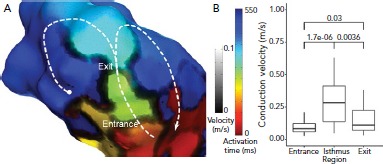
A: timing data has been extracted from the Rhythmia mapping system and reanalysed using custom scripts in MATLAB software (MathWorks). Activation time is represented by colour and identifies a single loop re-entrant ventricular tachycardia (VT) in the border of a large anteroseptal scar region. Activation proceeds through the VT isthmus before breaking out into the outer loop (white dashed line). To the right of the image, activation proceeds in a re-entrant loop (white arrow) but to the left, activation is stopped by a line of block (white circle). Conduction velocity is indicated by the grayscale overlay and clearly shows zones of very slow conduction or block defining the lateral margins of the isthmus. There is another line of block outside the isthmus which results in a single loop, rather than dual loop, VT circuit. There are regions of slow conduction in the entrance and exit of the isthmus. Other regions of slow conduction are present elsewhere in the ventricle, but do not play a direct role in the VT circuit. B: median conduction velocity in entrance, isthmus and exit zones, and median (apparent) conduction velocity in zones of complete block and functional block which define the isthmus. P-values for comparisons are shown. Source: Martin et al.18 Reproduced with permission from Wolters Kluwer Health.
The deceleration of activation wavefronts at entrance and exit zones may be due to one, or more likely a combination, of several factors. Activation in healthy myocardium and in the mid-isthmus is largely linear and orthogonal to fibre orientation. At entrance and exit zones, however, the wavefront curves around the lateral borders of the isthmus, are often perpendicular to fibre orientation. This abrupt change in activation vector as well as increased axial resistivity and myocardial thickness gradient, are likely to contribute to slowing. Further, there is greater slowing of activation in entrance zones due to collision of opposing wavefronts in double-loop circuits.[24]
The Role of Functional Block and Slow Conduction
As well as slow conduction playing an important role in the entrance and exit zones of the protected part of the VT circuit, regions of slow conduction and/or functional block also seem to be important in defining the VT isthmus. Early animal studies in a canine infarct model identified regions of functional block that were present during tachycardia. High-density mapping in animal and human studies has confirmed this finding. Lines of complete block with well-defined double potentials are observed. However, many VT circuits are also bordered, at least in part, by regions of very slow activation, evidenced by long fractionated EGMs (Figure 5).[17,18] Conduction in these lateral borders is sufficiently slow to protect the central isthmus.
Figure 5: Slow Conduction in the Borders of a Ventricular Tachycardia Isthmus.
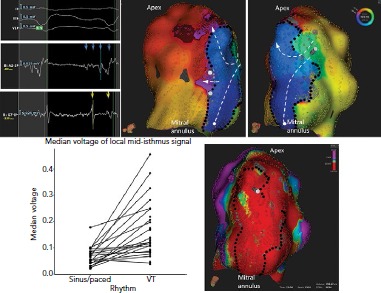
An activation map of ventricular tachycardia 18 years after MI. The isthmus is defined by a combination of lines of complete block (black dots) particularly in regions of very low voltage and slow conduction or functional block (gray dots). Activation proceeds from a single entrance to an apical exit (white dashed lines). There is also activation of a very large area of dead-end activation (white circle) with mid-diastolic activation, partially delimited by the mitral annulus. Source: Martin et al.18 Reproduced with permission from Wolters Kluwer Health.
Substrate mapping studies in an animal model identified critical sites in zones of maximal wavefront deceleration in sinus rhythm. These sites were located in regions of dense scar (<0.55 mV) and served as anchors of multiple VTs of different configurations and cycle lengths. Multiple VTs are common in clinical practice.[25]
Implications for Substrate Mapping
The increasing evidence for the role of functional block in VT circuits provides an explanation for the observation of more than one VT breaking out from the same region of scar. A region of slow conduction which acts as a lateral border for one VT may act as the entrance or exit zone for another (Figure 6). The role of functional block results in major limitation of current substrate-mapping approaches, which often rely on a single map generated in either sinus or a paced rhythm.[21] Mapping in a rhythm with a cycle length and activation wavefront orientations which differ to the clinical VTs may not identify regions of functional block that are critical to the VT isthmus.[26,27] Furthermore, not all LAVA and late potentials lie in critical parts of the VT circuit. Complete substrate elimination, while currently the strategy with the best supporting evidence, may not be entirely necessary for the elimination of all VTs.
Figure 6: A Critical Zone Anchoring Multiple Ventricular Tachycardias.
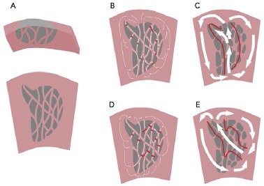
A: Many years after MI, there is an area of scar extending from the endocardium. There is a fine mesh of surviving fibres on the endocardial surface. B: In ventricular tachycardia (VT), there is slow conduction, collision and functional block to create a protected isthmus channel (red lines). C: Current high-resolution technologies do not capture the complex zig-zag activation in the scar but can identify the path of activation through the critical isthmus. D: A second VT in the same scar is characterised by collision and functional block at different sites, resulting in a different pattern of activation and breakout site. E: Mapped with a high-resolution electroanatomical system, VT2 appears to have a different isthmus, which overlaps with that mapped in VT1.
It has been suggested that there may be VT critical zones which serve as the focal point for wavefront slowing and curvature, which can lead to re-entry in multiple different morphologies, leading to multiple VTs.[25] Identification of these critical zones in clinical practice may improve the results of substrate mapping by identifying specific areas of LAVA. Strategies to demarcate such zones are needed, but approaches which use pacing from multiple sites and/or different cycle lengths have been shown to improve detection of poorly coupled fibres and are likely to be useful.[27] Evidence to support ablation of a targeted subset of LAVA with dynamic poor coupling comes from studies using close-coupled extra-stimuli to identify dynamic increases in EGM duration and latency. Although small, these studies have demonstrated a high rate of non-inducibility and low rate of VT recurrence with a targeted approach.[28,29]
Implications for Pace Mapping and Entrainment Mapping
One of the most interesting observations from high resolution studies is the poor correlation of activation mapping and entrainment mapping, particularly in exit zones, at this resolution. Entrainment from sites well beyond the breakout curvature of the activation map still allow concealed entrainment with post-pacing intervals that are consistent with pacing from within the circuit (Figure 7).[17] This may be because conduction velocities are relatively slow at the lateral edges of the breakout zone and so activation through this zone contributes very little to the overall morphology of the surface QRS complex. Ablation at these distal sites may fail to terminate tachycardia, however, as activation is still able to break out laterally to healthy myocardium. This phenomenon, although not formally studied, may also have implications for pace mapping. Some studies of pace mapping suggest that the preferred strategy would be to ablate at the entrance site of the identified VT isthmus, which perhaps alleviates this problem.[30] Conversely, entrainment and high-density mapping may complement each other. Entrainment remains useful in atrial macroreentry with high-density mapping, and high-density maps may allow a more focused entrainment strategy.[31,32]
Figure 7: Comparison of Activation and Pace Mapping of the Ventricular Tachycardia Exit.
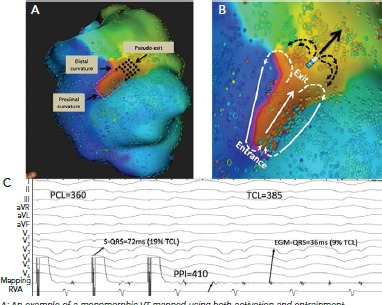
A: An example of a monomorphic VT mapped using both activation and entrainment techniques. The length of the isthmus determined by activation mapping was measured from the proximal curvature (entrance) to the distal curvature (exit) and is highlighted in a red dashed ellipse. Dimensions of the isthmus were also measured using standard entrainment criteria and included sites with concealed QRS on all 12 electrogram (EGM) leads and PPI-TCL ≤30 ms (gray dashed rectangle). Although the two methods similarly identified the proximal curvature (entrance) and the width of the common channel, entrainment mapping overestimated the length of the isthmus, particularly at the exit site. The pseudo-exit is the zone considered part of the circuit using entrainment mapping but not part of the circuit by activation mapping (black dots). C: An example of entrainment from a pseudo-exit site (electrode, shown in B). The bipolar EGM at the pacing site occurs just before the QRS complex (EGM to QRS of 36 ms; 9% of the TCL). Entrainment from this site resulted in concealed QRS fusion, as the stimulated pacing site assumes a similar wave front vector to the VT (solid arrow). However, in contrast to a true exit site, pacing from a pseudo-exit site resulted in a longer PPI with PPI-TCL of 25 ms. This is because the pacing site is beyond the distal curvature (white arrows) and propagation of its wave front in the figure-eight configuration (black arrows) assume a curvature shape that encounters a partially refractory tissue, both result in slower conduction and prolonged postpacing interval. PCL = paced cycle length; PPI: postpacing interval; RVA = right ventricular apex; TCL: tachycardia cycle length. Source: Anter et al. 2016.[17] Reproduced with permission from Wolters Kluwer Health.
Future Directions
The limitations of current technologies for mapping VT have been reviewed elsewhere, but recent developments in high-resolution mapping are unlikely to be the final improvements in the field.[33] The lower limit for electrode size and spacing, beyond which even smaller, more closely-spaced electrodes are no longer helpful, has not been reached. Anatomical studies suggest that the surviving fibres which support tachycardia are about 100 μm in diameter. It is likely that further miniaturisation of recording electrodes to this scale — and perhaps even beyond — will yield more nuanced data on characteristics of VT activation. Any improvement in mapping resolution, however must be matched by localisation accuracy to be clinically useful, as even very large numbers of poorly-located points will not provide an accurate assessment of the isthmus architecture.
The corresponding development of software systems to collect and annotate tens, and possibly hundreds of thousands of EGMs will also continue. Already the number of EGMs collected by current systems defies useful real-time manual analysis in clinical care. Algorithms to display activation throughout the tachycardia cycle length, such as ripple mapping in CARTO (Biosense Webster) or LumiPoint in Rhythmia (Boston Scientific), have been developed and are entering clinical practice.[34–37] More sophisticated algorithms to analyse signal characteristics, improving distinction of near-field and far-field signals, and improving annotation of local timing, are in development and will greatly aid the clinician in understanding the VT circuit. Another signal-processing algorithm which shows promise is omnipolar mapping, in which simultaneous analysis of multiple bipolar EGMs allows estimation of wavefront speed and direction from a single beat, assisting in rapid mapping of unstable tachycardias and minimising direction-dependent effects on voltage measurement.
Summary
High-density mapping technologies have improved our understanding of the characteristics of VT isthmuses. These are complex structures with multiple entrances and exits which are defined by a mixture of complete and functional block. These characteristics allow multiple VTs to arise from the same area of substrate. This has clear implications for substrate mapping and ablation strategies, and improved techniques to identify VT critical zones for targeted ablation may improve VT ablation outcomes.
Clinical Perspective
Ventricular tachycardia (VT) circuits are complex with multiple entrances, exits and dead ends. Tortuous isthmuses are common.
Local electrogram voltage in the VT isthmus is low, consistent with previous definitions of dense scar.
Regions of slow conduction play an important role in defining VT isthmuses. These functional elements may make identification of isthmuses in sinus or paced rhythm difficult.
Several VT circuits may be supported by a single VT critical zone, where a combination of anatomical and functional block supports re-entry.
References
- 1.de Chillou C, Lacroix D, Klug D et al. Isthmus characteristics of reentrant ventricular tachycardia after myocardial infarction. Circulation. 2002;105:726–31. doi: 10.1161/hc0602.103675. [DOI] [PubMed] [Google Scholar]
- 2.Ciaccio EJ, Ashikaga H, Kaba RA et al. Model of reentrant ventricular tachycardia based on infarct border zone geometry predicts reentrant circuit features as determined by activation mapping. Heart Rhythm. 2007;4:1034–45. doi: 10.1016/j.hrthm.2007.04.015. [DOI] [PMC free article] [PubMed] [Google Scholar]
- 3.Soejima K, Stevenson WG, Sapp JL et al. Endocardial and epicardial radiofrequency ablation of ventricular tachycardia associated with dilated cardiomyopathy: the importance of low-voltage scars. J Am Coll Cardiol. 2004;43:1834–42. doi: 10.1016/j.jacc.2004.01.029. [DOI] [PubMed] [Google Scholar]
- 4.Santangeli P, Frankel DS, Tung R et al. Early mortality after catheter ablation of ventricular tachycardia in patients with structural heart disease. J Am Coll Cardiol. 2017;69:2105–15. doi: 10.1016/j.jacc.2017.02.044. [DOI] [PubMed] [Google Scholar]
- 5.Tung R, Vaseghi M, Frankel DS et al. Freedom from recurrent ventricular tachycardia after catheter ablation is associated with improved survival in patients with structural heart disease: an International VT Ablation Center Collaborative Group study. Heart Rhythm. 2015;12:1997–2007. doi: 10.1016/j.hrthm.2015.05.036. [DOI] [PMC free article] [PubMed] [Google Scholar]
- 6.Josephson ME, Horowitz LN, Farshidi A. Continuous local electrical activity. A mechanism of recurrent ventricular tachycardia. Circulation. 1978;57:659–65. doi: 10.1161/01.CIR.57.4.659. [DOI] [PubMed] [Google Scholar]
- 7.Miller JM, Tyson GS, Hargrove WC et al. Effect of subendocardial resection on sinus rhythm endocardial electrogram abnormalities. Circulation. 1995;91:2385–91. doi: 10.1161/01.CIR.91.9.2385. [DOI] [PubMed] [Google Scholar]
- 8.Stevenson WG, Khan H, Sager P et al. Identification of reentry circuit sites during catheter mapping and radiofrequency ablation of ventricular tachycardia late after myocardial infarction. Circulation. 1993;88:1647–70. doi: 10.1161/01.CIR.88.4.1647. [DOI] [PubMed] [Google Scholar]
- 9.Koutalas E, Rolf S, Dinov B et al. Contemporary mapping techniques of complex cardiac arrhythmias – identifying and modifying the arrhythmogenic substrate. Arrhythm Electrophysiol Rev. 2015;4:19–27. doi: 10.15420/aer.2015.4.1.19. [DOI] [PMC free article] [PubMed] [Google Scholar]
- 10.Berte B, Relan J, Sacher F et al. Impact of electrode type on mapping of scar-related VT. J Cardiovasc Electrophysiol. 2015;26:1213–23. doi: 10.1111/jce.12761. [DOI] [PubMed] [Google Scholar]
- 11.Tschabrunn CM, Roujol S, Dorman NC et al. High-resolution mapping of ventricular scar: comparison between single and multielectrode catheters. piiCirc Arrhythm Electrophysiol. 2016;9:e003841. doi: 10.1161/CIRCEP.115.003841. [DOI] [PMC free article] [PubMed] [Google Scholar]
- 12.Takigawa M, Relan J, Martin R et al. Detailed analysis of the relation between bipolar electrode spacing and far- and near-field electrograms. JACC Clin Electrophysiol. 2019;5:66. doi: 10.1016/j.jacep.2018.08.022. [DOI] [PubMed] [Google Scholar]
- 13.de Bakker JM, van Capelle FJ, Janse MJ et al. Slow conduction in the infarcted human heart. ‘Zigzag’ course of activation. Circulation. 1993;88:915–26. doi: 10.1161/01.CIR.88.3.915. [DOI] [PubMed] [Google Scholar]
- 14.Hooks DA, Yamashita S, Capellino S et al. Ultra-rapid epicardial activation mapping during ventricular tachycardia using continuous sampling from a high-density basket (Orion™) catheter. J Cardiovasc Electrophysiol. 2015;26:1153–4. doi: 10.1111/jce.12685. [DOI] [PubMed] [Google Scholar]
- 15.Takigawa M, Frontera A, Thompson N et al. The electrical circuit of a hemodynamically unstable and recurrent ventricular tachycardia diagnosed in 35 s with the Rhythmia mapping system. J Arrhythm. 2017;33:505–7. doi: 10.1016/j.joa.2017.06.002. [DOI] [PMC free article] [PubMed] [Google Scholar]
- 16.Dillon SM, Allessie MA, Ursell PC, Wit AL. Influences of anisotropic tissue structure on reentrant circuits in the epicardial border zone of subacute canine infarcts. Circ Res. 1988;63:182–206. doi: 10.1161/01.RES.63.1.182. [DOI] [PubMed] [Google Scholar]
- 17.Anter ETC, Buxton AE, Josephson ME. High-resolution mapping of postinfarction reentrant ventricular tachycardia: electrophysiological characterization of the circuit. Circulation. 2016;134:314–27. doi: 10.1161/CIRCULATIONAHA.116.021955. [DOI] [PMC free article] [PubMed] [Google Scholar]
- 18.Martin R, Maury P, Bisceglia C et al. Characteristics of scar-related ventricular tachycardia circuits using ultra-high-density mapping. Circ Arrhythm Electrophysiol. 2018;11:e006569. doi: 10.1161/CIRCEP.118.006569. [DOI] [PubMed] [Google Scholar]
- 19.Sacher F, Tedrow UB, Field ME et al. Ventricular tachycardia ablation: evolution of patients and procedures over 8 years. Circ Arrhythm Electrophysiol. 2008;1:153–61. doi: 10.1161/CIRCEP.108.769471. [DOI] [PubMed] [Google Scholar]
- 20.Bogun F, Krishnan S, Siddiqui M et al. Electrogram characteristics in postinfarction ventricular tachycardia: effect of infarct age. J Am Coll Cardiol. 2005;46:667–74. doi: 10.1016/j.jacc.2005.01.064. [DOI] [PubMed] [Google Scholar]
- 21.Di Biase L, Burkhardt JD, Lakkireddy D et al. Ablation of stable VTs versus substrate ablation in ischemic cardiomyopathy: the VISTA randomized multicenter trial. J Am Coll Cardiol. 2015;66:2872–82. doi: 10.1016/j.jacc.2015.10.026. [DOI] [PubMed] [Google Scholar]
- 22.de Bakker JM, van Capelle FJ, Janse MJ et al. Reentry as a cause of ventricular tachycardia in patients with chronic ischemic heart disease: electrophysiologic and anatomic correlation. Circulation. 1988;77:589–606. doi: 10.1161/01.CIR.77.3.589. [DOI] [PubMed] [Google Scholar]
- 23.Kléber AG, Janse MJ, Wilms-Schopmann FJ et al. Changes in conduction velocity during acute ischemia in ventricular myocardium of the isolated porcine heart. Circulation. 1986;73:189–98. doi: 10.1161/01.CIR.73.1.189. [DOI] [PubMed] [Google Scholar]
- 24.Fast VG, Kléber AG. Role of wavefront curvature in propagation of cardiac impulse. Cardiovasc Res. 1997;33:258–71. doi: 10.1016/S0008-6363(96)00216-7. [DOI] [PubMed] [Google Scholar]
- 25.Anter E, Kleber AG, Rottmann M et al. Infarct-related ventricular tachycardia: redefining the electrophysiological substrate of the isthmus during sinus rhythm. JACC Clin Electrophysiol. 2018;4:1033–48. doi: 10.1016/j.jacep.2018.04.007. [DOI] [PubMed] [Google Scholar]
- 26.Martin C, Martin R, Wong T et al. Effect of activation wavefront on electrogram characteristics during ventricular tachycardia ablation. EP Europace. 2017;19(Suppl 1)(i):16. doi: 10.1093/europace/eux283.046. [DOI] [PubMed] [Google Scholar]
- 27.Tung R, Josephson ME, Bradfield JS, Shivkumar K. Directional influences of ventricular activation on myocardial scar characterization: voltage mapping with multiple wavefronts during ventricular tachycardia ablation. Circ Arrhythm Electrophysiol. 2016;9:e004155. doi: 10.1161/CIRCEP.116.004155. [DOI] [PubMed] [Google Scholar]
- 28.Shariat MH, Gupta D, Gul EE Ventricular substrate identification using close-coupled paced electrogram feature analysis. Europace. 2018. epub ahead of press. [DOI] [PubMed]
- 29.de Riva M, Naruse Y, Ebert M et al. Targeting the hidden substrate unmasked by right ventricular extrastimulation improves ventricular tachycardia ablation outcome after myocardial infarction. JACC Clin Electrophysiol. 2018;4:316–27. doi: 10.1016/j.jacep.2018.01.013. [DOI] [PubMed] [Google Scholar]
- 30.de Chillou C, Groben L, Magnin-Poull I et al. Localizing the critical isthmus of postinfarct ventricular tachycardia: the value of pace-mapping during sinus rhythm. Heart Rhythm. 2014;11:175–81. doi: 10.1016/j.hrthm.2013.10.042. [DOI] [PubMed] [Google Scholar]
- 31.Pathik B, Lee G, Nalliah C et al. Entrainment and high-density three-dimensional mapping in right atrial macroreentry provide critical complementary information: Entrainment may unmask ‘visual reentry’ as passive. Heart Rhythm. 2017;14:1541–9. doi: 10.1016/j.hrthm.2017.06.021. [DOI] [PubMed] [Google Scholar]
- 32.Kumar S, Tedrow UB, Stevenson WG. Entrainment mapping. Card Electrophysiol Clin. 2017;9:55–69. doi: 10.1016/j.ccep.2016.10.004. [DOI] [PubMed] [Google Scholar]
- 33.Graham AJ, Orini M, Lambiase PD. Limitations and challenges in mapping ventricular tachycardia: new technologies and future directions. Arrhythm Electrophysiol Rev. 2017;6:118–24. doi: 10.15420/aer.2017.20.1. [DOI] [PMC free article] [PubMed] [Google Scholar]
- 34.Jamil-Copley S, Vergara P, Carbucicchio C et al. Application of ripple mapping to visualize slow conduction channels within the infarct-related left ventricular scar. Circ Arrhythm Electrophysiol. 2015;8:76–86. doi: 10.1161/CIRCEP.114.001827. [DOI] [PubMed] [Google Scholar]
- 35.Luther V, Linton NW, Jamil-Copley S et al. A prospective study of ripple mapping the post-infarct ventricular scar to guide substrate ablation for ventricular tachycardia. Circ Arrhythm Electrophysiol. 2016;9:e004072. doi: 10.1161/CIRCEP.116.004072. [DOI] [PubMed] [Google Scholar]
- 36.Katritsis G, Luther V, Kanagaratnam P, Linton NW. Arrhythmia mechanisms revealed by ripple mapping. Arrhythm Electrophysiol Rev. 2018;7:261–4. doi: 10.15420/aer.2018.44.3. [DOI] [PMC free article] [PubMed] [Google Scholar]
- 37.Martin CA, Takigawa M, Martin R et al. Use of novel electrogram ‘Lumipoint’ algorithms to detect critical isthmus and abnormal potentials for ablation in ventricular tachycardia. EP Europace. 2018;20(Suppl 4)(iv):22–3. doi: 10.1093/europace/euy202.004. [DOI] [PubMed] [Google Scholar]
- 38.Magtibay K, Massé S, Asta J et al. Physiological assessment of ventricular myocardial voltage using omnipolar electrograms. J Am Heart Assoc. 2017;6:e006447. doi: 10.1161/JAHA.117.006447. [DOI] [PMC free article] [PubMed] [Google Scholar]
- 39.Massé S, Magtibay K, Jackson N et al. Resolving myocardial activation with novel omnipolar electrograms. Circ Arrhythm Electrophysiol. 2016;9:e004107. doi: 10.1161/CIRCEP.116.004107. [DOI] [PMC free article] [PubMed] [Google Scholar]


