

Abstract
In the current era of transcatheter device therapy, the prevalence of prosthetic aortic valves and their associated complications is increasing. Echocardiography remains the first-line imaging investigation for the assessment of prosthetic valve complications, however, this often fails to identify the underlying mechanism of prosthesis failure. Recently, cardiac CT has emerged as an imaging technique capable of providing high isotropic spatial resolution of the prosthetic valve and its utility can provide important complementary diagnostic information. In this pictorial review, we present a series of common prosthetic aortic valve complications imaged with cardiac CT and demonstrate how use of this modality can enhance diagnostic accuracy.
Introduction
The number of prosthetic aortic valve implantations performed in the United Kingdom is increasing, in part, due to improved surgical outcomes and the recent addition of transcatheter aortic valve implantation (TAVI).1 An inevitable by-product of the increased prevalence of these prostheses is the elevated incidence of prosthetic valve complications. To date, echocardiography remains the first-line modality to assess the haemodynamic performance of aortic valve prostheses, however, the isotropic resolution of cardiac CT offers complementary anatomical information to guide further management.2 The utility of cardiac CT is recognised in international guidelines, which emphasise that cardiac CT is particularly well-placed to diagnose valve thrombosis and pannus formation.3 In this pictorial review, we illustrate how cardiac CT provides a detailed structural information across a variety of prosthetic valve complications, thereby allowing physicians to more accurately diagnose the mechanism of prosthetic valve dysfunction.
Cardiac CT image acquisition
Prosthetic aortic valves seated within the aortic annulus are subjected to significant motion throughout the cardiac cycle. As such the acquisition of images using ECG-gating is mandatory to ensure adequate temporal resolution for visualisation of the prostheses and their surrounding anatomy. Current CT protocols for the coronary arteries have been optimised to provide submillimetre spatial resolution and a temporal resolution below 165 ms to minimise the effect of cardiac motion. Similar protocols can also be used to image prosthetic leaflet pathology. However, CT imaging of prosthetic heart valves poses some unique challenges that may benefit from slight modification to standard coronary protocols. Firstly, in order to reduce artefact from the metallic stent scaffold, high energy tube voltages (120 kV) may reduce photon starvation hypodense regions that lie adjacent to the frame.4 In cases with denser metallic frames (i.e. mechanical prosthetic valves) or in patients with a large body habitus, the tube voltage may need to be increased to 140 kV.5 Post-processing the images with a sharper reconstruction kernel provides improved definition of the margins of the scaffold and a more accurate measurement of the true internal diameter.6 Secondly, CT imaging is often required in the context of severe prosthesis dysfunction where aggressive rate control with beta-blockade may be clinically contraindicated. Of note, the clinical question plays an important role in selecting the appropriate phase. Prospective-ECG gating with padding at end-systole addresses issues relating to prosthetic valve obstruction and reduced leaflet motion, whereas mid-diastolic acquisition provides detailed anatomical information in cases of prosthetic leaflet thickening or in the assessment of transprosthesis regurgitation.5 Experienced cardiac CT centres now use cardiac CT in a wide variety of indications for assessing the mechanism of prosthetic valve dysfunction (Table 1). High resolution anatomical imaging of prosthetic valve complications using cardiac CT complements the functional assessment provided by other imaging modalities (Table 2). Examples of cases where cardiac CT adds diagnostic value in the context of prosthetic valve dysfunction are detailed below.
Table 1.
Indications for cardiac CT in aortic prosthetic valve dysfunction
| Indication/echocardiography finding | Potential cardiac CT findings |
| Change in trans-prosthesis velocities/gradient | Patient-prosthesis mismatch Structural valve deterioration with leaflet calcification Leaflet thrombosis Pannus formation Extrinsic compression of prosthesis (e.g. calcification, para-valvular plugs) |
| Trans-prosthetic valve regurgitation | Leaflet prolapse |
| Para-prosthetic valve regurgitation | Suture dehiscence Aneurysm formation Aortic root abscess |
| Infective endocarditis | Vegetation size/position Thrombus formation Aortic root abscess Erosive shunts Splenic abscess Mycotic aneurysm |
Table 2.
Comparison of cardiac CT versus other imaging modalities with respect to investigation of the dysfunctional prosthetic valve
| Echocardiography | Cardiac CT | MRI | |
| General strengths and weakness of each modality | + Fast, cost-effective and easy to use + Multiple views + Can assess LV size function and pulmonary pressure - Operator dependent - Body habitus can limit quality of images/Doppler recordings - Acoustic shadowing and artefact produced by prosthetic material |
+ 3D isotropic dataset + Excellent spatial resolution + Not limited by body habitus + Highly sensitive for calcification - Radiation exposure - Risks associated with contrast (nephrotoxcity and allergy) -Metallic artefacts |
+ No ionizing radiation + Good for aortic pathology + Tissue characterisation - Metallic artefact Limited spatial and temporal resolution - Limited data in prosthetic valves |
PPM onset —immediate
|
+ Identifies haemodynamic features of PPM (elevated transprosthetic gradient with reduced effective orifice area).7
- Artefact/acoustic shadowing limits structural assessment |
+ Can differentiate between PPM and prosthetic valvular dysfunction - Lack of haemodynamic assessment |
+ Can locate areas of flow acceleration using phase contrast velocity mapping - Limited spatial and temporal resolution impairs leaflet motion assessment |
Thrombus onset—early
|
+ Identifies haemodyamic effects of valve thrombosis (elevated gradients) - Unable to visualise small and laminar cusp thrombosis |
+ Accurate identification of thrombus location +Attenuation assessment (<90 HU) - Retrospective gating required to assess cusp |
+ Early gadolinium imaging can differentiate large thrombus from vascularized mass (e.g. tumour) - limited spatial and temporal resolution make accurate identification of smaller thrombi difficult |
Pannus onset ->12months
|
+ Identifies haemodynamic sequelae of pannus (elevated transprosthetic gradients) - Difficult to visualise pannus itself |
+ Accurate identification of pannus location +Tissue characterisation - No haemodynamic assessment |
+ Areas of flow acceleration and velocity mapping can be used to assess degree of prosthetic valve obstruction - Unable to directly visualise pannus |
Structural valve degeneration onset—years
|
+ Identifies functional significance of structural valve degeneration (stenosis/regurgitation) - Artefacts may limit diagnosis of mechanism of dysfunction |
+ Accurate structural assessment of valve integrity and calcification + Structural interventional planning - Unable to assess haemodynamic impact of structural dysfunction |
+ Identifies flow acceleration and origins of valvular/paravalvular regurgitation + Can assess impact of volume changes on cardiac chambers and functions - Leaflet motion may be identified but often difficult to accurately assess |
Endocarditis onset—anytime
|
+ High temporal resolution allows for identification of independently mobile vegetations + Haemodynamic sequelae of valve damage can be assessed - Artefact from metallic valve often limits accurate assessment |
+ Accurate identification of cusp vegetations/ abscesses and pseudoaneurysms - Unable to assess haemodynamic impact of abnormalities |
+ Identifies origins of valvular and paravalvular regurgitation secondary to valve destruction + Can assess impact of volume and flow changes on cardiac chambers and functions - Vegetations too small to be detected by MR |
HU, Hounsfiedl unit; LV, left ventricular; PPM, patientprosthesis mismatch.
Prosthetic valve complications using cardiac CT
Hypoattenuation leaflet thickening/Leaflet thrombosis
A recent observation, first described by Pache et al in 2013,8 is the phenomenon of bioprosthetic leaflet thickening associated with hypoattenuated material that occurs early following TAVI. Localised thrombogenesis on prosthetic aortic valves is driven by activation of coagulation factors and perturbations in flow patterns.9 In regions of blood stasis and platelet activation, iodinated contrast fails to opacify thrombi producing the appearance of a thickened leaflet with low attenuation at similar CT densities to those observed with left ventricular thrombi.10 Of note, a large area of hypoattenuation on the bioprosthetic leaflet may be associated restricted leaflet motion and an increased trans-prosthesis gradient, particularly if more than one leaflet is involved. (Figure 1, Table 2) Supporting evidence from several cardiac CT registries have observed complete resolution with the initiation of therapeutic anticoagulation.8–10
Figure 1.

TAVI hypoattenuated leaflet thickening several months after transcatheter aortic valve implantation (26 mm Spaien 3, Edwards Lifesciences). Elevated trans-prosthesis pressure gradients were observed on echocardiography and 4D cardiac CT was performed (A). Hypoattenuation of all three prosthesis cusps was present with a restricted excursion of the leaflets during ventricular systole (B). Laminar deposition of low attenuation material on the aortic aspect of the prosthesis results in the thickened appearance of the leaflet (C). Resolution with anticoagulation and restoration of normal leaflet motion is observed with this CT finding suggesting that it may represent subacute thrombus. 4D, four-dimensional; TAVI, transcatheter aortic valve implantation.
Pannus formation
Pannus is composed of a biofilm of fibroblasts and microvascular networks which envelope prostheses. Often this manifests as infiltration from beneath the sewing ring in to the base of the leaflets thereby restricting their motion (Figure 2). There is heterogeneous CT density of the tissue with discrete regions of calcification and contrast enhancement from neovascularisation of fibrotic material. Whereas thrombus has a CT number of <90 Hounsfield units (HUs), the CT intensity distribution curve of pannus is typically >145 HU reflecting the different material composition (Figure 2C).11 Differentiating thrombus from pannus formation can be aided by measuring the CT attenuation of the tissue, as fibroblast and neo-vascularised material have similar values to the left ventricular septum, whereas thrombus is associated with low CT attenuation below values within the myocardium. (Figure 3).
Figure 2.

Bioprosthetic aortic valve pannus formation. Increased trans-prosthesis pressure gradients were recorded after surgical bioprosthetic aortic valve replacement (21 mm Carpentier-Edwards Perimount MagnaEase, Edwards Lifesciences). Sagittal multiplanar reconstruction of the aortic root (A) revealed thickening of the subvalvular apparatus propagating from the interventricular septum and aorto-mitral continuity. Axial views of the tissue at the base of the prosthesis (B) confirmed circumferential thickening below the level of the sewing ring (arrowed). The CT intensity distribution curve supported the presence of pannus (C).
Figure 3.

Differentiating thrombus from pannus formation on cardiac CT. Referencing the CT attenuation of tissue to the adjacent myocardium can help differentiate low attenuation thrombus (A) from fibrotic regions of pannus (B).
Structural valve degeneration
Structural valve degeneration is a multifaceted process primarily driven by calcification that results in thickening, retraction or perforation of the bioprosthetic leaflets. These morphological changes lead to prosthesis stenosis/regurgitation or a mixture of both which limits the durability of the prosthesis. Echocardiographic assessment has been the first line investigation for classifying prosthesis haemodynamics, but poor echocardiographic windows, artefacts and acoustic shadowing the structural abnormality may limit detailed assessment of the aetiology. In these cases, cardiac CT can be usefully employed to provide high resolution images of prosthesis morphology and leaflet motion (Figure 4).12
Figure 4.

Bioprosthetic structural valve degeneration with cusp prolapse Due to the high risk of complication from a repeat sternotomy, pre-procedural cardiac CT was performed prior to consideration for valve-in-valve TAVI in a patient with a bioprosthetic aortic valve replacement (19 mm Pericardial Elan, Vascutek). (A) Cardiac CT demonstrated failure of cusp coaptation with prolapse of the left prosthetic cusp (arrowed) into the LVOT (B), arrowed, (C), schematic representation. Cardiac CT highlighted an acquired interventricular septal aneurysm related to the angulation of the regurgitant jet. LVOT, left ventricular outflow tract; TAVI, transc atheteraortic valve implantation.
Prosthetic valve endocarditis
Prosthetic valve endocarditis is a potentially fatal condition with a 20–34% mortality rate.13 Prompt diagnosis is therefore vital to prevent severe morbidity and death. Cardiac CT can accurately identify large vegetations and paraprosthesis abscess or pseudoaneurysm formation. (Figures 5 and 6)14 Incorporating cardiac CT in the routine work-up for prosthetic valve endocarditis positively influences the clinical treatment strategy in up to a quarter of patients with suspected prosthetic valve endocarditis.15
Figure 5.
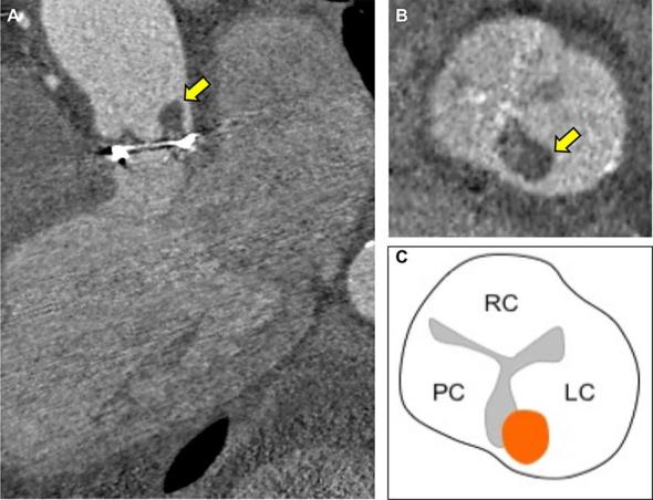
Bioprosthetic aortic valve endocarditis with thrombotic vegetation An elderly male presented with vertebral discitis and systemic symptoms associated with Streptococcus salivarious. 7 years previously, he had undergone surgical bioprosthetic aortic valve replacement (25 mm Mitroflow, Sorin) Transoesophageal echocardiography was unable delineate vegetations on the aortic bioprosthesis and a detailed anatomical assessment with cardiac CT was performed. (A, 3-chamber reconstruction) Cardiac CT demonstrated a low attenuation (84 HU) 8 mm lesion adhering to the commissure of the left prosthetic cusp (arrowed). (B short axis of aortic bioprosthesis with thrombotic vegetation arrowed and C, corresponding schematic representation) The low CT number is in-keeping with a thrombotic vegetation on the prosthesis. HU, Hounsfield unit.
Figure 6.

Sinus of valsalva saccular pseudoaneurysm. Following a mechanical aortic valve replacement, cardiac CT was employed to measure the size and relationship of the saccular pseudoaneurysm to the great vessels and the coronaries (A). The LMCA (yellow arrow) is tented by a large saccular pseudoaneurysm that tracks along the left lateral and posterior margin of the aortic root (B) ventricular systole and (C) ventricular diastole with pseudoaneurysm. There is systolic compression (<50% luminal stenosis) of the LMCA (D, arrowed) between the common pulmonary artery and saccular aneurysm with restoration of the LMCA diameter during ventricular diastole (E, arrowed). LMCA, left main coronary artery.
Conclusion
Cardiac CT provides detailed anatomical information that can help stratify the management of patients with suspected prosthetic aortic valve complications. Its high spatial resolution is well suited to the detection of prosthetic valve thrombosis, pannus formation, infective vegetations, and para-prosthetic pathology. The greater availability of cardiac CT with its expansion for coronary artery disease assessment, means that cardiac CT is now frequently incorporated into diagnostic algorithms to assess prosthetic aortic valve dysfunction, complimenting the haemodynamic information provided by echocardiography.
Footnotes
Funding: JPMA is supported by BHF Clinical Research Training Fellowship no. FS/17/51/33096. MRD is supported by the Sir Jules Thorn Biomedical Research Award 2015 (15/JTA) and by the British Heart Foundation (FS/14/78/31020). AJM is supported by the Chief Scientific Office (CGA/17/53).
Contributor Information
Jack Patrick Morrell Andrews, Email: Jack.Andrews@ed.ac.uk.
Timothy RG Cartlidge, Email: timcartlidge1@gmail.com.
Marc Robert Dweck, Email: marc.dweck@ed.ac.uk.
Alastair J Moss, Email: alastairmoss@gmail.com.
REFERENCES
- 1. Grant SW, Hickey GL, Ludman P, Moat N, Cunningham D, de Belder M, et al. Activity and outcomes for aortic valve implantations performed in England and Wales since the introduction of transcatheter aortic valve implantation. Eur J Cardiothorac Surg 2016; 49: 1164–73. doi: 10.1093/ejcts/ezv270 [DOI] [PubMed] [Google Scholar]
- 2. Moss AJ, Dweck MR, Dreisbach JG, Williams MC, Mak SM, Cartlidge T, et al. Complementary role of cardiac CT in the assessment of aortic valve replacement dysfunction. Open Heart 2016; 3: e000494. doi: 10.1136/openhrt-2016-000494 [DOI] [PMC free article] [PubMed] [Google Scholar]
- 3. Baumgartner H. The 2017 ESC/EACTS guidelines on the management of valvular heart disease: What is new and what has changed compared to the 2012 guidelines? Wien Klin Wochenschr 2018; 130:168–71. doi: 10.1007/s00508-017-1297-5 [DOI] [PubMed] [Google Scholar]
- 4. Habets J, Symersky P, Leiner T, de Mol BA, Mali WP, Budde RP. Artifact reduction strategies for prosthetic heart valve CT imaging. Int J Cardiovasc Imaging 2012; 28: 2099–108. doi: 10.1007/s10554-012-0041-5 [DOI] [PMC free article] [PubMed] [Google Scholar]
- 5. Jilaihawi H, Asch FM, Manasse E, Ruiz CE, Jelnin V, Kashif M, et al. Systematic CT methodology for the evaluation of subclinical leaflet thrombosis. JACC Cardiovasc Imaging 2017; 10: 461–70. doi: 10.1016/j.jcmg.2017.02.005 [DOI] [PubMed] [Google Scholar]
- 6. Rajani R, Attia R, Condemi F, Webb J, Woodburn P, Hodson D, et al. Multidetector computed tomography sizing of bioprosthetic valves: guidelines for measurement and implications for valve-in-valve therapies. Clin Radiol 2016; 71: e41–e48. doi: 10.1016/j.crad.2015.10.013 [DOI] [PubMed] [Google Scholar]
- 7. Zoghbi WA. Recommendations for evaluation of prosthetic valves with echocardiography and doppler ultrasound: a report from the American Society of Echocardiography’s Guidelines and Standards Committee and the Task Force on Prosthetic Valves, developed in conjunction with the American College of Cardiology Cardiovascular Imaging Committee, Cardiac Imaging Committee of the American Heart Association, the European Association of Echocardiography, a registered branch of the European Society of Cardiology, the Japanese Society of Echocardiography and the Canadian Society of Echocardiography, endorsed by the American College of Cardiology Foundation, American Heart Association, European Association of Echocardiography, a registered branch of the European Society of Cardiology, the Japanese Society of Echocardiography, and Canadian Society of Echocardiography. J Am Soc Echocardiogr 2009; 22: p975–1014. [DOI] [PubMed] [Google Scholar]
- 8. Pache G, Blanke P, Zeh W, Jander N. Cusp thrombosis after transcatheter aortic valve replacement detected by computed tomography and echocardiography. Eur Heart J 2013; 34: 3546. doi: 10.1093/eurheartj/eht316 [DOI] [PubMed] [Google Scholar]
- 9. Puri R, Auffret V, Rodés-Cabau J, Thrombosis BV. Bioprosthetic valve thrombosis. J Am Coll Cardiol 2017; 69: 2193–211. doi: 10.1016/j.jacc.2017.02.051 [DOI] [PubMed] [Google Scholar]
- 10. Bittencourt MS, Achenbach S, Marwan M, Seltmann M, Muschiol G, Ropers D, et al. Left ventricular thrombus attenuation characterization in cardiac computed tomography angiography. J Cardiovasc Comput Tomogr 2012; 6: 121–6. doi: 10.1016/j.jcct.2011.12.006 [DOI] [PubMed] [Google Scholar]
- 11. Gündüz S, Özkan M, Kalçik M, Gürsoy OM, Astarcioğlu MA, Karakoyun S, et al. Sixty-four-section cardiac computed tomography in mechanical prosthetic heart valve dysfunction: thrombus or pannus. Circ Cardiovasc Imaging 2015; 8. doi: 10.1161/CIRCIMAGING.115.003246 [DOI] [PubMed] [Google Scholar]
- 12. Chenot F, Montant P, Goffinet C, Pasquet A, Vancraeynest D, Coche E, et al. Evaluation of anatomic valve opening and leaflet morphology in aortic valve bioprosthesis by using multidetector CT: comparison with transthoracic echocardiography. Radiology 2010; 255: 377–85. doi: 10.1148/radiol.0000082294 [DOI] [PubMed] [Google Scholar]
- 13. Vongpatanasin W, Hillis LD, Lange RA. Prosthetic heart valves. N Engl J Med 1996; 335: 407–16. doi: 10.1056/NEJM199608083350607 [DOI] [PubMed] [Google Scholar]
- 14. Fagman E, Perrotta S, Bech-Hanssen O, Flinck A, Lamm C, Olaison L, et al. ECG-gated computed tomography: a new role for patients with suspected aortic prosthetic valve endocarditis. Eur Radiol 2012; 22: 2407–14. doi: 10.1007/s00330-012-2491-5 [DOI] [PubMed] [Google Scholar]
- 15. Habets J, Tanis W, van Herwerden LA, van den Brink RB, Mali WP, de Mol BA, et al. Cardiac computed tomography angiography results in diagnostic and therapeutic change in prosthetic heart valve endocarditis. Int J Cardiovasc Imaging 2014; 30: 377–87. doi: 10.1007/s10554-013-0335-2 [DOI] [PubMed] [Google Scholar]