Abstract
The growing demand for personal healthcare monitoring requires a challenging combination of performance, size, power, and cost that is difficult to achieve with existing gas sensor technologies. This paper presents a new CMOS monolithic gas sensor microsystem that meets these requirements through a unique combination of electrochemical readout circuits, post-CMOS planar electrodes, and room temperature ionic liquid (RTIL) sensing materials. The architecture and design of the CMOS-RTIL-based monolithic gas sensor are described. The monolithic device occupies less than 0.5mm2 per sensing channel and incorporates electrochemical biasing and readout functions with only 1.4mW of power consumption. Oxygen was tested as an example gas, and results show that the microsystem demonstrates a highly linear response (R2 = 0.995) over a 0 – 21% oxygen concentration range, with a limit of detection of 0.06% and a 1 second response time. Monolithic integration reduces manufacturing cost and is demonstrated to improve limits of detection by a factor of five compared to a hybrid implementation. The combined characteristics of this device offer an ideal platform for portable/wearable gas sensing in applications such as air pollutant monitoring.
Keywords: monolithic microsystem, room temperature ionic liquid, electrochemical, gas sensor
I. Introduction
Airborne pollutants are known to threaten human health and safety, causing discomfort, illness, and even death, particularly among susceptible individuals such as those with pre-existing cardiovascular or respiratory problems as well as infants and the elderly [1, 2]. To avoid such threats, there is a growing need for portable, low cost, low power, multi-gas sensor systems suitable for constantly examining the individual surrounding environment. Monolithic gas sensors that combine sensor devices and analog front-end circuitry in a single microelectronics chip are an ideal solution because of their low production cost, low noise, high resolution, low power and compact size, making them suitable for wearable applications [2].
A variety of monolithic gas sensors have been reported in the last decade including cantilever gas sensors [3, 4], thermoelectric gas sensors [5, 6], acoustic resonator gas sensor [7], metal oxide gas sensors [7, 8], bioluminescent gas sensors [10], chemiresistor gas sensors [10, 11], polymer-based chemical gas sensor [13] and chemical field effect transistor (chem-FET) gas sensors [14]. These technologies have demonstrated capability for sensing several airborne quantities of interest including NO2, CO, and volatile organic compounds (VOCs). However, several drawbacks are inherent with these existing sensor technologies and/or their on-CMOS sensor fabrication processes. For example, the bioluminescent gas sensor requires an external light source and thus is not a fully monolithic approach; chemiresistor gas sensors suffer significant baseline drifts; and cantilever thermoelectric and metal oxide based gas sensors require high temperature operation that limits battery life for portable applications. Moreover, the bulk MEMS processes used to fabricate cantilever thermoelectric, metal oxide and chemFET-based gas sensors add process complexity that negatively impact device cost.
Electrochemical techniques are a good candidate for battery-power portable/wearable gas sensors due to their inherent combination of sensitivity, selectivity and low power consumption [13, 14]. However, traditional electrochemical gas sensors using a liquid electrolyte require bulky Clark-type cell structures to seal the electrolyte within a gas permeable membrane. Such 3D structures are complicated to miniaturize and especially difficult to integrate monolithically with CMOS chips. As an alternative, room temperature ionic liquid (RTIL) has been utilized as an electrolyte for electrochemical gas sensors [17]. Compared to aqueous electrolytes, RTILs are nonvolatile and conductive compounds consisting entirely of ions. With properties such as negligible vapor pressure, wide potential window, and high thermal stability, RTILs offer a promising electrolyte option for robust electrochemical gas sensors that can operate in extreme conditions. A variety of gases have been successfully sensed using RTILs, including oxygen [16–21], ambient toxic gases (e.g. NO2 [24], NO [25], NH3 [26], H2S [27]) and VOCs [26, 27]. The nonvolatile nature of RTIL enables membrane-free cell design [20, 21, 26] and paves a path to monolithic implementation of electrochemical sensors and CMOS instrumentation chips that permit significant decrease in device size and cost.
Combining RTIL sensing materials with a low power electrochemical instrumentation chip requires simultaneously addressing the functional needs of the sensors and the circuits while also resolving monolithic fabrication compatibility needs. This paper presents the first CMOS monolithic gas sensor microsystem that integrates RTIL-based electrochemical sensors and CMOS electrochemical instrumentation circuits within a single chip to address the power/size/cost requirements for wearable environmental monitoring. Results for an example environmental gas, oxygen, demonstrate good sensing performance and verify that monolithic integration improves sensor resolution. The architecture of the monolithic RTIL electrochemical gas sensor microsystem is described in section II. The electrochemical circuit design is given in section III. Section IV illustrates the post-CMOS sensor fabrication process. Test results of the circuit and the monolithic gas sensor system are given in section IV, followed by a conclusion in section V.
II. System Architecture
A. Electrochemical sensor system
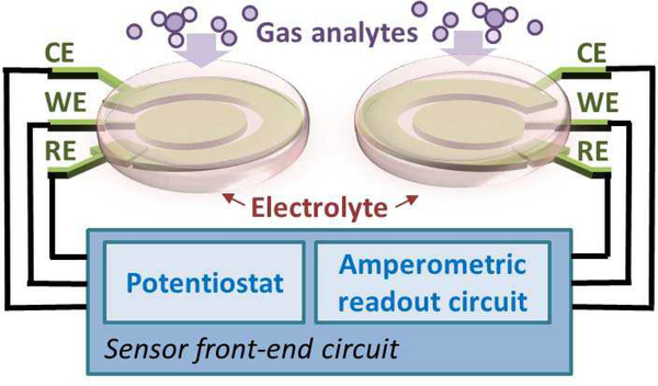
As shown in Fig. 1, an electrochemical sensor system consists of an electrochemical transducer and an instrumentation circuit that is often called a “front-end” in microsystems because it occurs up front, at the point of signal origin. The transducer is a set of electrodes that work in conjunction with an electrolyte, and often an applied electrical stimulus, to transform target quantities (species and concentrations) into an electrical signal that can be amplified, conditioned and recorded by the front-end instrumentation circuit.
Fig. 1.
Block diagram of an amperometric electrochemical sensor system.
Amperometry is one of the most commonly used electro-chemical methods for acquiring qualitative information and has been shown to work well for RTIL-based gas sensors [17, 20]. In a typical three-electrode configuration, amperometry involves applying an electrochemical bias potential, Vref, at which specific chemical reactions are catalyzed between a reference electrode (RE) and a working electrode (WE). The resulting electrical current, Iout, between the WE and the counter electrode (CE) is then recorded as a measure of the electrochemical response current. Although other electrode configurations can be used, the three-electrode setup is very common because it eliminates error associated with ionic current through the resistive electrolyte creating a so-called “IR” drop, voltage drop due to current I through resistance R.
The sensing principle for electrochemical gas sensors is described as follows [15]. A specific reduction/oxidation (redox) reaction involving gas analytes that dissolve within the electrolyte takes place at the electrode/electrolyte interface and thus generates a redox current, as shown in Fig. 1. However, this only occurs when the electrode/electrolyte interface is biased at (or beyond) a specific voltage. The resulting redox current is proportional to the gas analyte concentration in the electrolyte, and the species is related to the bias potential that generated the reaction.
As shown in Fig. 1, the electrochemical instrumentation circuit for amperometry methods consists of a potentiostat and a readout circuit that are connected to the sensing electrodes. The potentiostat provides the required bias voltage and current for a three-electrode configuration, and the amperometric read-out circuit amplifies the response current, typically converting it to a voltage for subsequent processing including analog-to-digital conversion.
B. CMOS monolithic sensor microsystem concept
RTIL-based electrochemical sensors can be implemented in a variety of structures, such as probes [16, 17, 28], Clark cells [20], paper-based planar structure [19, 29], Teflon based planar structure [15, 30], and silicon-based planar structure [20, 21, 26]. RTIL serves as the electrolyte in the electrochemical transducer. To reach the electrode/electrolyte interface, analytes must diffuse through the RTIL layer, and because different analytes will have different diffusion velocities in different RTILs, the RTIL chemical composition provides a degree of selectivity to RTIL-based gas sensors [20, 33]. Because of RTILs’ nonvolatile property, the containers or gas permeable membranes necessary to seal a volatile electrolyte can be eliminated, which can significantly simplify system integration. Microfabrication technology enables planar electrochemical cell structures that only need three layers: a substrate for physical support, planar electrodes and RTILs as a supporting electrolyte. Thus, an RTIL-based electrochemical sensor can be implemented by two simple steps [14, 15, 24] wherein, first, planar electrodes are patterned on a chemically-inert, non-conductive substrate (such as silicon nitride) and, second, RTILs are coated on the electrodes to form the electrochemical transducer.
The instrumentation circuit for most electrochemical sensors, including RTIL gas sensors, can readily be implemented as a microelectronics chip using a standard CMOS foundry process. Many examples are discussed in a recent review of CMOS electrochemical circuits [34]. Such integrated circuit (IC) chips form a rigid silicon die with a passivation layer on the top surface, typically of silicon nitride, to electrically insulate the surface and protect underlying circuits from moisture and chemical corrosion.
A monolithic approach for sensor integration, where sensing materials are formed directly on the surface of the instrumentation chip, can significantly lower production cost and power consumption, minimize the system size, and improve the detection limit. To construct a monolithic microsystem by stacking an IC chip and a planar RTIL-base sensor together, structure compatibility must first be considered. In a monolithic system, the top passivation layer of the IC chip can be the substrate of the RTIL-based electrochemical sensor. The passivation layer will not only provide physical support as a substrate for an RTIL-based electrochemical sensor, but also protect the circuit from any potential corrosion introduced by the electrochemical reaction on the WE. In addition, due to silicon nitride’s hydrophilic response to RTILs, it is possible to form a thin layer of RTIL on chip’s surface, enabling rapid diffusion of gas analytes through the RTIL layer and thus promoting a fast sensor response. The contact angle between the RTIL and a gold electrode surface was reported to be only 18° [35], indicates a hydrophilic response between RTIL and gold. Because of their high surface tension, small-volume RTIL droplets could firmly stick to the chip surface, and we have observed that RTIL will stay in the same position even when the sensor was stored in a variety of orientations for over three weeks. The CMOS process also provides on-chip electrical contacts, enabling a direct connection between circuits and electrochemical sensor electrodes formed on the surface of the CMOS chip.
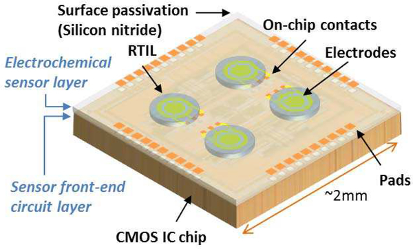
Based on these compatibility features, a CMOS monolithic RTIL-based electrochemical microsystem concept was developed to include both sensors and front-end instrumentation circuits as shown in Fig. 2. By stacking the RTIL-based electrochemical sensor layer and front-end instrumentation circuit layer together, a monolithic microsystem is achieved. To realize such RTIL-based sensor on CMOS IC chip, the fabrication process only involves on-CMOS electrode patterning and RTIL coating. The post-CMOS process is much simpler than other types of monolithic gas sensors, providing a comparatively low-cost solution. Meanwhile, the CMOS frontend circuit will provide a compact and low power consumption solution suitable for portable gas sensing applications.
Fig. 2.
Conceptual illustration of the CMOS monolithic RTIL-based electrochemical gas sensor microsystem.
III. CMOS Design
To realize the monolithic RTIL gas sensor chip concept, the first step is to implement a CMOS front-end instrumentation circuit chip. As shown in Fig. 1, the sensor front-end circuit consists of a potentiostat and an amperometric readout circuit. This section describes the CMOS circuit design of each block.
A. Potentiostat
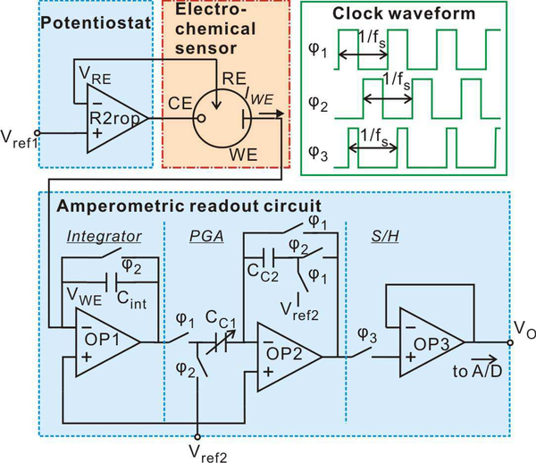
A typical potentiostat topology using only one operational amplifier (opamp), as shown in Fig. 3, was adopted to save power consumption. Input voltage Vref1 is applied to the positive input of the opamp. When an electrochemical cell is attached to the opamp as shown in Fig. 3, the negative feedback loop forces the voltages at CE and RE to be the same, as desired. Furthermore, this configuration forces the voltage at RE (VRE) to precisely follow (be equal to) Vref1, the applied voltage at the positive opamp input.
Fig. 3.
Schematic of the monolithic microsystem, consisting of the amperometric instrumentation circuit and the RTIL-based sensor. Green rectangle block illustrates the clock waveform.
A rail-to-rail opamp (R2rop) [36] was implemented to maximize the potential window available for for electrochemical sensing. This is particularly important in low-power applications using battery power sources. The R2rop opamp was designed to operate from a 5V power supply and drive the output RE voltage bias in the range of 0.1V to 4.9 V.
B. Amperometric Readout Circuit
To maximize the RTIL sensor sensitivity, the low-noise amperometric readout circuit topology shown in Fig. 3 was adopted [37]. Since capacitive feedback readout structures achieve low noise compared to resistive feedback and current conveyer structures [38], a capacitive integrator was used to convert the electrochemical response current into a voltage. In the first stage integrator, the negative input node of opamp OP1 is connected to the electrochemical cell WE. When a bias of Vref2 is applied on the positive input of OP1, the voltage applied on WE is held equal to Vref2. Thus the voltage between WE and RE can be held constantly equal to Vref2-Vref1 during sensor operation. The output voltage of the integrator is sent to a programmable gain amplifier (PGA) stage with a gain determined by the ratio of capacitances CC1/CC2. To output a stable voltage, a sample and hold (S/H) circuit is used as the final stage.
To reduce 1/f noise and amplifier DC offset, the correlated double sampling (CDS) technique [39] was implemented. CDS requires several switches and non-overlapping switch clock signals, φ1, φ2, as illustrated in Fig. 3. All clocks, φ1, φ2, and φ3, were produced by an on-chip clock generator block from an external master clock.
The final amperometric readout output voltage is given by
| (1) |
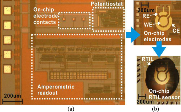
where IWE is the current collected at WE, fs is the frequency of the switch clocks, and Cint is the integrator capacitor value. The CMOS front-end instrumentation circuit was designed and fabricated in a 0.5 μm foundry CMOS process. Fig. 4(a) shows a close-up of the 2.2 mm × 2.2 mm fabricated chip, where the instrumentation circuit occupies approximately 0.48mm2 and includes surface contacts for on-chip WE, RE, and CE electrodes.
Fig. 4.
Die photographs of fabricated CMOS electrochemical instrumentation chip; (a) chip as received from foundry with functional blocks labeled, (b) chip after post-CMOS fabrication of (top) on-CMOS electrodes and (bottom) on-CMOS RTIL sensor/electrolyte layer.
IV. Monolithic Sensor Fabrication
As described in Section II.B, the monolithic RTIL sensor fabrication process involves standard foundy CMOS IC fabrication and post-CMOS sensor fabrication. The post-CMOS fabrication includes on-CMOS electrode patterning and on-CMOS RTIL coating.
Two concerns need be addressed at the CMOS circuit design stage, specifically with layout placement and routing. First, to connect circuits directly with on-chip electrodes, surface contact openings through the final overglass insulating layer must be included with the layout design. Second, if a flat surface electrode is desired, the top CMOS metal layer should not be used in areas where the electrodes will be formed. Considering the reliability of electrode pattern and surface routing, top metal layer were avoided during circuit routing to create a flat chip surface. With these considerations, the front-end instrumentation circuit described in Section III was fabricated.
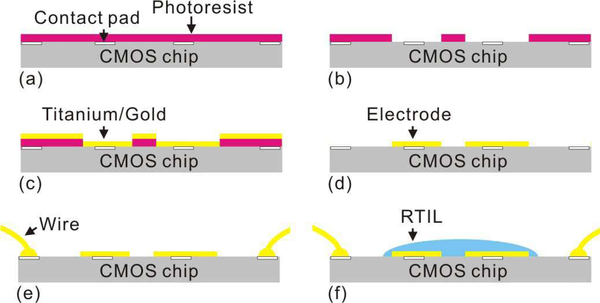
The fabricated CMOS chips were provided by the foundry as individual die. Thus, to pattern post-CMOS thin film electrodes on the surface of the chips, previously reported dielevel processing procedures were employed [40]. The die was first attached to a 3” silicon wafer with glue. Then, as shown in Fig. 5, photoresist (Shipley 1813) was spin-coated on the die (3000 rpm spin speed) followed by a 10 min soft bake at 95 °C in the oven. 10 s of UV exposure through the electrode pattern mask was performed followed by a 45 s of development by AZ 352 developer. Then 5nm-thick titanium film and 100nm-thick gold film was deposited on the die using physical vapor deposition (PVD) by Edward 360 thermal evaporator. After deposition, the photoresist was rinsed off by acetone, methanol and DI water, and the on-CMOS gold electrode pattern was formed by the lift-off process.
Fig. 5.
Post-CMOS pocess flow for on-chip RTIL-based sensor fabrication: Photoresist is spin-coated (a) and developed (b). Titanium and gold is deposited by PVD (c). Photoresist is then rinsed off to leave the electrode (d). CMOS chip with on-chip electrode is wire bonded to package (e). A droplet of RTIL is casted on the electrodes (f).
After the electrodes were patterned, the CMOS chip was wire bonded to a DIP-40 package. A droplet of RTIL (around 16nL) was cast on the electrodes by a pipette tip. Here, high-purity 1-butyl-1-methylpyrrolidinium bis(trifluoro-methylsulfonyl)imide ([C4mpy][NTf2]) RTIL was chosen due to its relative low viscosity, high chemical stability, and its success in sensing oxygen, sulfur dioxide and methane [15, 18, 30, 37–39].
Following this fabrication procedure, an on-CMOS RTIL-based gas sensor with disk geometry was fabricated. As shown in Fig. 4(b)-top, the radius of the disk-shaped WE is 100 μm, the inner radius of the annular CE is 120 μm and outer radius is 200 μm. The gap between WE and CE is 20 μm. As shown in Fig. 4(b)-bottom, the RTIL covers the whole electrode area. The average thickness of RTIL is around 26 μm. Fig. 5(f) illustrates the final cross section of the CMOS circuit, on-chip electrodes and RTIL sensor layer that together form a monolithic CMOS gas sensor.
V. Results
A. Test Setup
To characterize performance of the CMOS amperometric instrumentation circuit, a custom evaluation printed circuit board (PCB) was designed to interface the chip with a data acquisition (DAQ) card (National Instruments, DAQ USB-6259) and low noise battery supply. The DAQ generates digital signals to configure and control the chip, to provide input analog voltages, and to acquire and digitize analog outputs from the chip. Displaying and storing data was performed by a PC running LabVIEW. A source meter (Keithley 6430) was used as an accurate input current source to evaluate the current readout circuit.
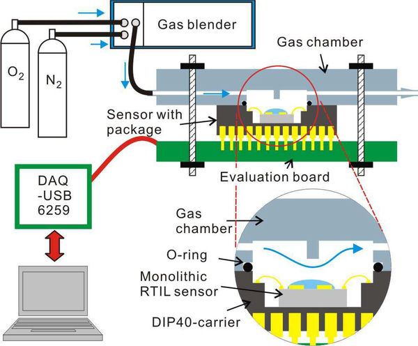
To test the sensing performance of the CMOS monolithic RTIL-based sensor, the electrochemical experimental station shown in Fig. 6 was constructed. Oxygen was selected as an example analyte. Oxygen and nitrogen (as background gas) concentrations were controlled and mixed using a Gas Blender 100 (MCI Instruments, Inc.) to vary oxygen concentration from 0% to 21%. The total flow rate was fixed to 100 standard cubic centimeters per minute (sccm) to circumvent the influence of differential gas flow rate. A small gas reaction chamber was created over the instrument chip DIP40 package using a 3D-printed (Connex 350 3D printer) cap that was sealed by a Viton o-ring. Including the cavity of the DIP package, the total gas chamber volume was 0.48 cm3, which allows the total volume to be replaced, for example to measure sensor response time, in 0.3 s.
Fig. 6.
The electrochemical test setup.
B. CMOS circuits test Results
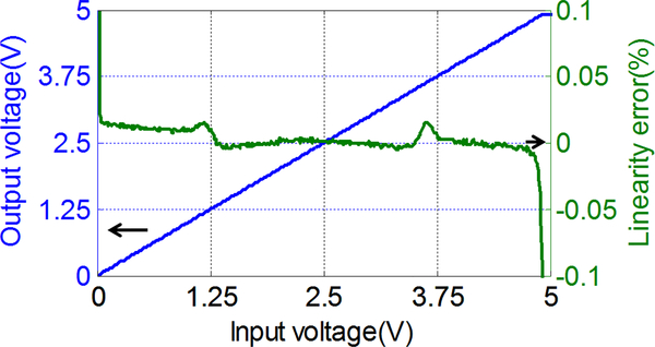
The CMOS amperometric instrumentation circuit occupies 800 μm × 600 μm area as shown in Fig. 4. In static operation mode, the circuit consumes 280 μA with a 5 V voltage supply. To characterize the effective voltage working range of the potentiostat, the R2rop was connected as a united-gain buffer and the positive input node voltage was scanned from 0 to 5 V. The output voltage and the linearity error are plotted as a function of input voltage in Fig. 7. The absolute error of the output voltage is less than 0.05 % over the range from 0.03 V to 4.90 V. The result is in good agreement with the design expectation (from 0.1 V to 4.9 V), maximizing the applicable potential window available for electrochemical sensors with a limited supply voltage.
Fig. 7.
The R2rop output voltage range and linearity error as a function of input voltage. The absolute error of the output voltage is less than 0.05% over the range from 0.03 V to 4.90 V.
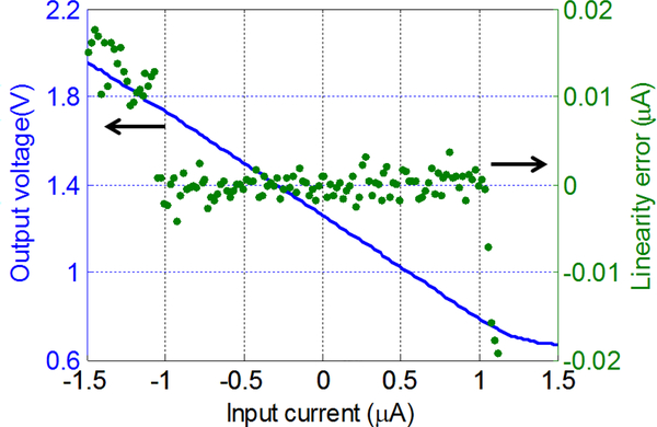
To characterize the performance of the amperometric read-out circuit, the input current was swept from −1.5 μA to 1.5 μA and output voltage Vo was recorded by the DAQ USB-6259. The amperometric readout clock frequency fs was set to 100 kHz and Vref2 was set to 1.3 V. The output voltage and linearity error are plotted as a function of the input current in Fig. 8. The input current in the range of −1 μA to 1 μA shows a good linearity with the output voltage in the range of 1.74 V to 0.78 V where the absolute linearity errors are less than 4 nA (0.2% of range). By adjusting fs from 10 Hz to 1 MHz, the dynamic readout range can be varied from 100 pA to 10 μA, and linearity error will scale roughly with current range. For example, in the 100 pA range (fs = 10 Hz), the measured linearity error was only 2 pA (1% of range), which represents the best current resolution of this circuit. A performance summary of the CMOS front-end electrochemical instrumentation circuit is given in Table I.
Fig. 8.
Amperometric readout output range and linearity error as a function of input current when fs = 100 kHz, Vref2 = 1.3 V. In the range of −1 μA to 1 μA, the absolute linearity error is less than 4 nA.
TABLE I.
Performance summary of the CMOS front-end circuit
| Power supply | 5 V |
|---|---|
| Steady current | 280 μA |
| Area | 600 μm × μm |
| Input/output range of potentiostat | 0.03 – 4.90 V |
| Current readout range (bi-direction) | 100 pA – 10 μA |
| Current linearity error | 2 pA – 4 nA |
C. Electrochemical system test Results
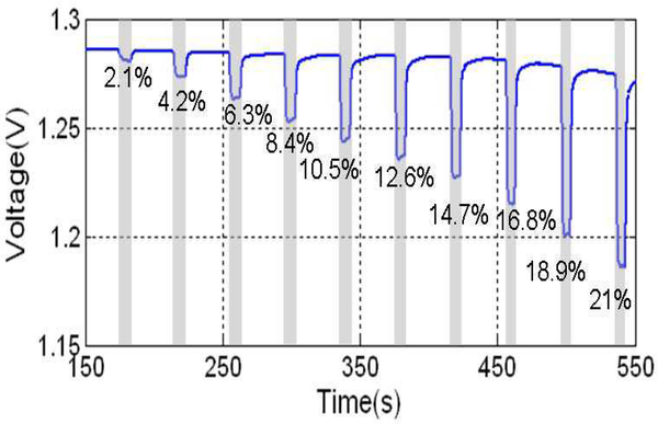
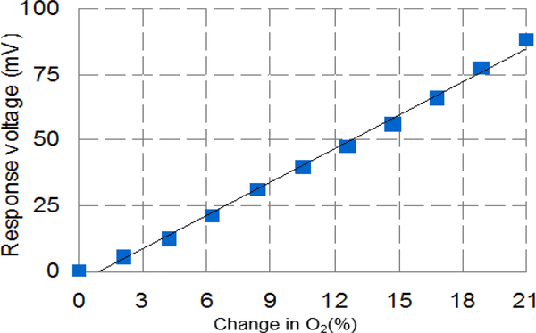
To verify the functionality of the monolithic RTIL-based CMOS sensor, the sensor was tested with oxygen as an example target analyte. Using the Gas Blender 100, oxygen concentration was varied from 0 – 21% with a step of 2.1%. Oxygen exposures were 10 s in duration preceded and followed by exposure to pure nitrogen for 30 s. The amperometric instrumentation circuit was set to Vref1 = 2.1 V, Vref2 = 1.3 V, which provides a sensor bias potential (VWE-VRE) of −0.8 V. The clock switching frequency was set to fs = 100 kHz, which had previously been observed as providing the proper input current range for this oxygen concentration and this on-CMOS RTIL-based sensor. The output voltage of the monolithic sensor was recorded and is plotted as a function of time in Fig. 9. The step response values at each concentration were calculated by subtracting the baseline (average of responses prior to introduction of new oxygen concentration) from the average current amplitude at each oxygen step. These values, plotted in Fig. 10, form the oxygen calibration curve, which indicates that the relationship between response voltage Vr(mV) and oxygen concentration CO2(%) can be expressed by
| (2) |
Fig. 9.
Output of amperometric readout circuit for on-CMOS RTIL-based sensor response to oxygen. Oxygen concentration varies from 0 – 21% with a step of 2.1%. Oxygen exposures were 10 s in duration, preceded and followed by exposure to pure nitrogen for 30 s. The amperometric circuit was set to Vref1 = 2.1 V and Vref2 = 1.3 V (the sensor was applied at −0.8V respectively), and fs=100 kHz.
Fig. 10.
Oxygen calibration curve for monolithic RTIL-based gas sensor using data extracted from Fig. 9. A high level of linearity (R2 = 0.995) was achieved.
Thus, the sensitivity of the monolithic sensor response was estimated as 4.23 mV/%. The R2 value of 0.995 implies a high level of linearity demonstrated by the monolithic sensor response to oxygen.
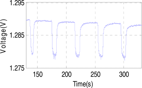
Repeatability tests were performed by alternatingly purging 4.2% oxygen and pure nitrogen for 5 cycles over ~150 seconds. The resulting output voltage is shown in Fig. 11. Although the sensor shows a slight drift due to the latency of oxygen desorption, after subtracting the baseline value, the response voltage ΔV shows a good repeatability with an average value of 10.36 mV and a standard deviation of only 89μV. The corresponding repeatable limit of detection (LOD) for oxygen, defined as three times the standard deviation, was found to be 0.06%. In addition, to further address the baseline drift issue, we have developed a new transient double potential amperometry method [42] which could be implemented in future CMOS instrumentation designs.
Fig. 11.
Repeatability test. Constant-potential current response measured over five cycles of alternate exposure to 4.2% oxygen and pure nitrogen flow at an applied bias of −0.8 V. The standard deviation of the five test cycles is 89 μV and the corresponding repeatable LOD of oxygen is 0.06%.
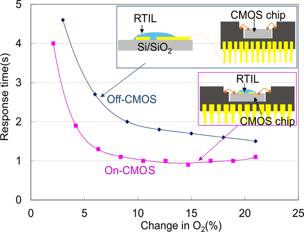
To evaluate the performance benefits of monolithic integration, a second sensor was implemented by constructing an off-chip RTIL sensor and connecting it to the CMOS instrumentation chip in a hybrid, wired, fashion. The off-chip RTIL sensor was fabricated on a thermally oxidized silicon substrate containing electrodes of exactly the same size and geometry as the monolithic sensor. And the RTIL coating was applied in exactly the same manner as the monolithic sensor. The off-chip sensor was then connected with same CMOS front-end instrumentation circuit and tested in oxygen following the same test procedure as the monolithic sensor. Response time, defined as the time period between the 10% and 90% of the reaction current, of both off-CMOS sensor and on-CMOS sensor were extracted from sensor step response tests and are plotted as a function of step change in oxygen concentration in Fig. 12. For identical RTIL sensors, the onCMOS sensor demonstrates a faster response that saturates at about 1 sec where, presumably, diffusion limits of O2 in the RTIL are reached. In comparison, commercial gas sensors, such as the Advanced Micro Instruments (AMI) oxygen sensor have response times ranging from 8s to 30s. In addition to response time, signal noise level and full response range were also measured for both off-CMOS and on-CMOS sensors, and results are listed in Table II. The LOD of oxygen detection was calculated based on the sensitivity and measured voltage noise level, and the on-CMOS sensor shows nearly a fivefold improvement in LOD. Because the only difference between the on- and off-chip test conditions is that the off-chip system requires wiring between the sensor electrodes and the chip circuitry, the monolithic device demonstrates that both response time and LOD have been improved by eliminating the wiring parasitics and environmental noise that can be coupled through them.
Fig. 12.
Off-CMOS and on-CMOS sensor response time characterized by the amperometric readout circuit. The response time saturates around 1 sec.
TABLE II.
Off-CMOS and on-CMOS electrochemical RTIL-based sensor noise level comparison
| On-CMOS (Monolithic) | Off-CMOS | |
|---|---|---|
| Noise level | 55 μv | 608 μV |
| Response at 21% O2 | 86 mV | 136 mV |
| LOD of O2 | 0.06% | 0.28% |
VI. Conclusion
This paper presents the first monolithic RTIL-based electrochemical CMOS gas sensor microsystem. The monolithic microsystem includes a compact CMOS amperometric instrumentation circuit and on-CMOS RTIL-based electrochemical gas sensor. The circuit was implemented in 0.5 μm CMOS technology with a 5 V voltage supply range and only consumes 280 μA. The chip provides both potentiostat and readout functions, achieving rail-to-rail voltage support and permitting a range of bi-directional current readout from 100 pA to 10 μA with linearity error as low as 2pA. Utilizing a post-CMOS fabrication process, the RTIL-based sensor was fabricated on the surface of the CMOS instrumentation chip. Using oxygen as an example gaseous analyte, the monolithic gas sensor exhibits a high level of linear response (R2 = 0.995) in the range of 0 – 21% oxygen, with LOD of 0.06%. Compared to an off-chip implementation, the monolithic RTIL sensor exhibits nearly 2x improvement in response time and 5x improvement in LOD. Because RTIL has been demonstrated as an effective sensor for many gases, this monolithic gas sensor microsystem provides a platform suitable for many portable/wearable gas monitoring applications.
Acknowledgment
The authors acknowledge Brian Wright and Gregg Mulder for assistant of 3D printing of the gas chamber and gas test setup. Thanks to Dr. Z. Wang for sensor testing consultation. The post-CMOS fabrication process was performed in Keck Microfabrication Facility.
This work was supported by the National Institutes of Health under Grant NIH_R01ES022302.
Contributor Information
Heyu Yin, Department of Electrical and Computer Engineering, Michigan State University, East Lansing, MI 48824, USA (yinheyu@msu.edu)..
Xiaoyi Mu, Apple Inc., 1 Infinite Loop, Cupertino, CA 95014, USA; muxiaoyi@gmail.com.
Haitao Li, Maxim Integrated Products, Inc., 160 Rio Robles, San Jose, CA 95034..
Xiaowen Liu, RippleInfo Co., Ltd. Jiangsu, China 215000..
Andrew J. Mason, Department of Electrical and Computer Engineering, Michigan State University, East Lansing, MI 48824, USA..
References
- [1].Brook RD, “Cardiovascular effects of air pollution,” Clin. Sci, vol. 115, no. 6, pp. 175–187, 2008. [DOI] [PubMed] [Google Scholar]
- [2].Lave LB and Seskin EP, Air pollution and human health. 2013. [DOI] [PubMed] [Google Scholar]
- [3].Hagleitner C, Hierlemann A, Lange D, Kummer A, Kerness N, Brand O and Batltes H, “Smart single-chip gas sensor microsystem.,” Nature, vol. 414, no. 6861, pp. 293–296, 2001. [DOI] [PubMed] [Google Scholar]
- [4].Philippe J, Arndt G, Colinet E, Savoye M, Ernst T, Ollier E and Arcamone J, “Fully monolithic and ultra-compact NEMS-CMOS selfoscillator based-on single-crystal silicon resonators and low-cost CMOS circuitry,” Proc. IEEE Int. Conf. Micro Electro Mech. Syst, pp. 1071–1074, 2014. [Google Scholar]
- [5].Afridi MY, Suehle JS, Zaghloul ME, Berning DW, Cavicchi RE, Semanick S, Montgomery CB and Taylor CJ, “A monolithic CMOS microhotplate-based gas sensor system,” IEEE Sens. J, vol. 2, no. 6, pp. 644–655, 2002. [Google Scholar]
- [6].Santra S, Guha PK, Ali SZ, Hiralal P, Unalan HE, Covington JA, Amaratunga GAJ, Milne WI, Gardner JW and Udrea F, “ZnO nanowires grown on SOI CMOS substrate for ethanol sensing,” Sensors Actuators, B Chem, vol. 146, no. 2, pp. 559–565, 2010. [Google Scholar]
- [7].Johnston ML, Edrees H, Kymissis I, and Shepard KL, “Integrated VOC vapor sensing on FBAR-CMOS array,” Proc. IEEE Int. Conf. Micro Electro Mech. Syst, pp. 846–849, 2012. [Google Scholar]
- [8].Hagleitner C, Hierlemann a., Brand O, and Baltes H, “CMOS Single Chip Gas Detection Systems — Part I,” Sensors Updat, vol. 11, no. 1, pp. 101–155, 2002. [Google Scholar]
- [9].Filipovic L and Selberherr S, “Performance and Stress Analysis of Metal Oxide Films for CMOS-Integrated Gas Sensors,” Sensors, vol. 15, no. 4, pp. 7206–7227, 2015. [DOI] [PMC free article] [PubMed] [Google Scholar]
- [10].Islam SK, Vijayaraghavan R, Zhang M, Ripp S, Caylor SD, Weathers B, Moser S, Terry S, Blalock BJ and Sayler GS, “Integrated circuit biosensors using living whole-cell bioreporters,” IEEE Trans. Circuits Syst. I Regul. Pap, vol. 54, no. 1, pp. 89–98, 2007. [Google Scholar]
- [11].Tzeng T et al. , “A Portable Micro Gas Chromatography System for Lung Cancer Associated Volatile Organic Compound Detection,” vol. 51, no. 1, pp. 259–272, 2016. [Google Scholar]
- [12].Mu X, Covington E, Rairigh D, Kurdak C, Zellers E, and Mason AJ, “CMOS monolithic nanoparticle-coated chemiresistor array for microscale gas chromatography,” IEEE Sens. J, vol. 12, no. 7, pp. 2444–2452, 2012. [Google Scholar]
- [13].Hierlemann A, “Integrated chemical microsensor systems in CMOStechnology,” 13th Int. Conf. Solid-State Sensors, Actuators Microsystems, 2005 Dig. Tech. Pap. TRANSDUCERS ‘05., vol. 2, pp. 1134–1137, 2005. [Google Scholar]
- [14].Barillaro G and Strambini LM, “An integrated CMOS sensing chip for NO2 detection,” Sensors Actuators, B Chem, vol. 134, no. 2, pp. 585–590, 2008. [Google Scholar]
- [15].Stetter JR, Korotcenkov G, Zeng X, Tang Y, and Liu Y, “Electrochemical gas sensors: fundamentals, fabrication and parameters,” Chem. sensors Compr. Sens. Technol, vol. 5, no. June, pp. 1–89, 2011. [Google Scholar]
- [16].Stetter JR and Li J, “Amperometric gas sensors - A review,” Chem. Rev, vol. 108, no. 2, pp. 352–366, 2008. [DOI] [PubMed] [Google Scholar]
- [17].Yin H, Wan H, Lin L, Zeng X, and Mason AJ, “Miniaturized Planar RTIL-based Eletro-chemical Gas Sensor for Real-Time Point-of-Exposure Monitoring,” Healthcare Innovation Point-Of-Care Technologies Conference (HI-POCT), pp. 85–88. 2016. [Google Scholar]
- [18].Toniolo R, Dossi N, Pizzariello A, Doherty AP, Susmel S, and Bontempelli G, “An oxygen amperometric gas sensor based on its electrocatalytic reduction in room temperature ionic liquids,” J. Electroanal. Chem, vol. 670, pp. 23–29, 2012. [Google Scholar]
- [19].Wang R, Okajima T, Kitamura F, and Ohsaka T, “A Novel Amperometric O2 Gas Sensor Based on Supported Room-Temperature Ionic Liquid Porous Polyethylene Membrane-Coated Electrodes,” Electroanalysis, vol. 16, no. 12, pp. 66–72, 2004. [Google Scholar]
- [20].Wang Z, Lin P, Baker GA, Stetter J, and Zeng X, “Ionic liquids as electrolytes for the development of a robust amperometric oxygen sensor,” Anal. Chem, vol. 83, no. 18, pp. 7066–7073, 2011. [DOI] [PubMed] [Google Scholar]
- [21].Hu C, Bai X, Wang Y, Jin W, Zhang X, and Hu S, “Inkjet printing of nanoporous gold electrode arrays on cellulose membranes for high-sensitive paper-like electrochemical oxygen sensors using ionic liquid electrolytes,” Anal. Chem, vol. 84, no. 8, pp. 3745–3750, 2012. [DOI] [PubMed] [Google Scholar]
- [22].Huang XJ, Aldous L, Omahony AM, Del Campo FJ, and Compton RG, “Toward membrane-free amperometric gas sensors: A microelectrode array approach,” Anal. Chem, vol. 82, no. 12, pp. 5238–5245, 2010. [DOI] [PubMed] [Google Scholar]
- [23].Xiong SQ, Wei Y, Guo Z, Chen X, Wang J, Liu JH and Huang XJ, “Toward membrane-free amperometric gas sensors: An ionic liquid-nanoparticle composite approach,” J. Phys. Chem. C, vol. 115, no. 35, pp. 17471–17478, 2011. [Google Scholar]
- [24].Nádherná M, Opekar F, and Reiter J, “Ionic liquid-polymer electrolyte for amperometric solid-state NO 2 sensor,” Electrochim. Acta, vol. 56, no. 16, pp. 5650–5655, 2011. [Google Scholar]
- [25].Ng SR, Guo CX, and Li CM, “Highly Sensitive Nitric Oxide Sensing Using Three-Dimensional Graphene/Ionic Liquid Nanocomposite,” Electroanalysis, vol. 23, no. 2, pp. 442–448, 2011. [Google Scholar]
- [26].Ji X, Banks CE, Silvester DS, Aldous L, Hardacre C, and Compton RG, “Electrochemical ammonia gas sensing in nonaqueous systems: A comparison of propylene carbonate with room temperature ionic liquids,” Electroanalysis, vol. 19, no. 21, pp. 2194–2201, 2007. [Google Scholar]
- [27].O’Mahony AM, Silvester DS, Aldous L, Hardacre C, and Compton RG, “The electrochemical reduction of hydrogen sulfide on platinum in several room temperature ionic liquids,” J. Phys. Chem. C, vol. 112, no. 20, pp. 7725–7730, 2008. [Google Scholar]
- [28].Zevenbergen MAG, Wouters D, Dam VAT, Brongersma SH, and Crego-Calama M, “Electrochemical sensing of ethylene employing a thin ionic-liquid layer,” Anal. Chem, vol. 83, no. 16, pp. 6300–6307, 2011. [DOI] [PubMed] [Google Scholar]
- [29].Dossi N, Toniolo R, Pizzariello A, Carriho E, Piccin E, Battiston S and Bontempelli G, “An electrochemical gas sensor based on paper supported room temperature ionic liquids,” Lab Chip, vol. 12, no. 1, pp. 153–158, 2012. [DOI] [PubMed] [Google Scholar]
- [30].Toniolo R, Dossi N, Pizzariello A, Doherty AP, and Bontempelli G, “A Membrane Free Amperometric Gas Sensor Based on Room Temperature Ionic Liquids for the Selective Monitoring of NO x,” Electroanalysis, vol. 24, no. 4, pp. 865–871, 2012. [Google Scholar]
- [31].Toniolo R, Dossi N, Pizzariello A, Casagrande A, and Bontempelli G, “Electrochemical gas sensors based on paper-supported room-temperature ionic liquids for improved analysis of acid vapours,” Anal. Bioanal. Chem, vol. 405, no. 11, pp. 3571–3577, 2013. [DOI] [PubMed] [Google Scholar]
- [32].Mu X, Wang Z, Guo M, Zeng X, and Mason AJ, “Fabrication of a miniaturized room temperature ionic liquid gas sensor for human health and safety monitoring,” 2012 IEEE Biomed. Circuits Syst. Conf, vol. 1, pp. 140–143, 2012. [Google Scholar]
- [33].Li H, Liu X, Li L, Mu X, Genov R, and Mason A, “CMOS Electrochemical Instrumentation for Biosensor Microsystems: A Review,” Sensors J, vol. 17, no. 1, p. 74, Dec. 2017. [DOI] [PMC free article] [PubMed] [Google Scholar]
- [34].Hogervorst R, Tero JP, and Huijsing JH, “A Compact Power-Efficient 3 V CMOS Rail-to-Rail Input/Output Operational Amplifier for VLSI Cell Libraries,” IEEE J. Solid-State Circuits, vol. 29, no. 12, pp. 1505–1513, 1994. [Google Scholar]
- [35].Li L, Liu X, Qureshi WA, and Mason AJ, “CMOS amperometric instrumentation and packaging for biosensor array applications,” IEEE Trans. Biomed. Circuits Syst, vol. 5, no. 5, pp. 439–448, 2011. [DOI] [PubMed] [Google Scholar]
- [36].Kim D, Goldstein B, Tang W, Sigworth FJ, and Culurciello E, “Noise analysis and performance comparison of low current measurement systems for biomedical applications.,” IEEE Trans. Biomed. Circuits Syst, vol. 7, no. 1, pp. 52–62, 2013. [DOI] [PubMed] [Google Scholar]
- [37].Enz CC and Temes GC, “Circuit techniques for reducing the effects of Op-Amp imperfections: Autozeroing, correlated double sampling, and chopper stabilization,” Proc. IEEE, vol. 84, no. 11, pp. 1584–1614, 1996. [Google Scholar]
- [38].Li L, Liu X, and Mason AJ, “Die-level photolithography and etchless parylene packaging processes for on-CMOS electrochemical biosensors,” in Circuits and Systems (ISCAS), IEEE International Symposiumon, 2012, pp. 2401–2404. [Google Scholar]
- [39].Wang Z, Mu X, Guo M, Huang Y, Mason AJ, and Zeng X, “Methane Recognition and Quantification by Differential Capacitance at the Hydrophobic Ionic Liquid-Electrified Metal Electrode Interface,” J. Electrochem. Soc, vol. 160, no. 6, pp. B83–B89, 2013. [Google Scholar]
- [40].Mu X, Member S, Wang Z, Zeng X, Mason AJ, and Member S, “Room temperature ionic-liquid electrochemical gas sensor array system for real-time mine safety monitoring,” IEEE SENSORS Conf.„ vol. 13, no. 10, pp. 3976–3981, 2013. [Google Scholar]
- [41].Wan H, Yin H, Lin L, Zeng X, and Mason AJ, “Miniaturized planar room temperature ionic liquid electrochemical gas sensor for rapid multiple gas pollutants monitoring,” Sensors Actuators, B Chem, vol. 255, pp. 638–646, 2018. [DOI] [PMC free article] [PubMed] [Google Scholar]
- [42].Wan H, Yin H, and Mason AJ, “Rapid measurement of room temperature ionic liquid electrochemical gas sensor using transient double potential amperometry,” Sensors Actuators, B Chem, vol. 242, pp. 658–666, 2017. [DOI] [PMC free article] [PubMed] [Google Scholar]


