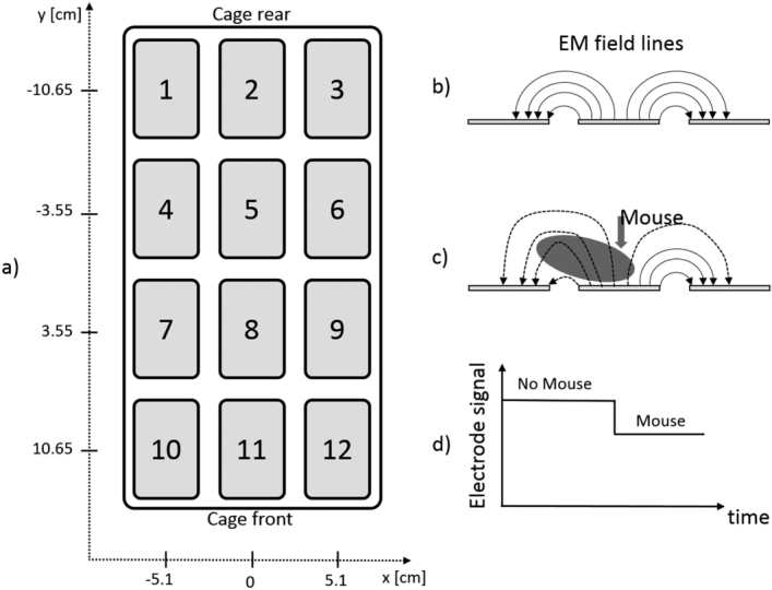
Figure 2.

Panel a) shows the CST board with electrode numbering and the coordinates (x, y) of each electrode. Panel b) shows a side view of three electrodes together with a pictorial representation of the electromagnetic (EM) field lines (representing actual EM field lines is out of scope for this paper). Panel c) shows the effect of the presence of a mouse over an electrode that modifies the EM field lines distribution, thus causing a drop of the electrode signal (related to a change in electrical capacitance) as shown in panel d).
