Abstract
Most of the current closed-loop DBS devices use a single biomarker in their feedback loop which may limit their performance and applications. This paper presents design, fabrication, and validation of a programmable multi-biomarker neural sensor which can be integrated into closed-loop DBS devices. The device is capable of sensing a combination of low-frequency (7-45 Hz), and high-frequency (200-1000 Hz) neural signals. The signals can be amplified with a digitally programmable gain within the range 50-100 dB. The neural signals can be stored into a local memory for processing and validation. The sensing and storage functions are implemented via a combination of analog and digital circuits involving preamplifiers, filters, programmable post-amplifiers, microcontroller, digital potentiometer, and flash memory. The device is fabricated, and its performance is validated through: (i) bench tests using sinusoidal and pre-recorded neural signals, (ii) in-vitro tests using pre-recorded neural signals in saline solution, and (iii) in-vivo tests by recording neural signals from freely-moving laboratory mice. The animals were implanted with a PlasticsOne electrode, and recording was conducted after recovery from the electrode implantation surgery. The experimental results are presented and discussed confirming the successful operation of the device. The size and weight of the device enable tetherless back-mountable use in pre-clinical trials.
Keywords: Circuits, Closed-loop, Multiple Biomarkers, Neural sensor, Programmable
I. Introduction
A recent review of the literature reveals that numerous efforts have been made to implement a feedback loop into conventional open-loop deep brain stimulation (DBS) platforms to produce closed-loop DBS devices [1]. Closed-loop DBS devices utilize neural recording circuitry that enables adaptive DBS via monitoring of neural signals as biomarkers of neurological disorders. Among different biomarkers, electrophysiological biomarkers are believed to convey desirable information for closing the feedback loop in DBS systems [2].
Alpha band (8-14 Hz) activity of local field potentials (LFPs) is one of the potential electrophysiological biomarkers. The study by Neumann et al. [3] suggests that alpha-band activity in the limbic system could be a potential biomarker for the severity of symptoms in major depressive disorder. In this case, the closed-loop DBS device should suppress aberrant alpha-band activity [3]. Also, alpha-band activity is biomarker of Parkinson’s disease (PD). In PD, alpha-band power is maximal in the pedunculopontine nucleus (PPN) region, correlating with improved gait performance in PD [4].
Beta band (13-30 Hz) activity of LFPs is also a biomarker of PD. It is decreased either by dopaminergic medication [5] or during electrical stimulation [6]. This reduction in the beta-band oscillations is shown to be correlated with improvement of rigidity, akinesia and bradykinesia [7], as well as freezing of gait [8] symptoms of PD. The correlation between beta-band activity and PD shows that closed-loop DBS should monitor beta-band activity from the sub-thalamic nucleus (STN) region as an effective biomarker [9-11].
Slow-gamma band (sG: 30-45 Hz) activity of LFPs is a potential electrophysiological biomarker that a generic closed-loop DBS device should monitor. Maling et al. [12] showed that increased thalamic sG activity correlates with symptom relief following DBS in humans with Tourette’s syndrome. In addition, suppression of the sG activity is shown to be linked with DBS-induced tremor symptom reduction in PD patients [13]. These findings have led to the hypothesis that sG-band activity of LFPs in the STN brain region should be monitored as an effective biomarker in closed-loop DBS devices.
The slow and fast high-frequency oscillation (HFO) bands (200-300 Hz and 300-400 Hz, respectively) of LFPs need to be monitored in closed-loop DBS devices. In humans, the HFO-band activity was observed in epilepsy [14]. In the epileptic brain, HFO-band activity is generated locally and appears frequently [15, 16]. Zijlmans et al. [17] suggested HFO-band activity as a biomarker of epilepsy. In PD, the HFO-band activity was reported by Foffani et al. [18]. They showed that the 300-Hz rhythm is boosted either in dopaminergic medication or voluntary movements. They [18, 19] concluded that DBS of the STN region could be enhanced by inducing HFO-band activity, which is absent in PD. López-Azcárate et al. [20] recorded LFPs from PD patients treated with STNDBS. They observed that HFO-band amplitude was coupled with the beta phase in off-motor state. Apart from epilepsy and PD, the existence of HFO-band activity was also shown in the STN-LFPs of patients suffering from essential tremor and dystonia [21]. Özkurt et al. [22] identified a slow HFO (sHFO) and a fast HFO (fHFO) component in the range of 200-300 Hz and 300-400 Hz, respectively. They observed that the ratio of fHFO- and sHFO-band activity increases after levodopa intake, suggesting the STN-HFO-band activity could be a neurophysiological biomarker of the dopaminergic and motor state in PD. Wang et al. [23] suggest that the correlation between HFO-band activity and akinesia could be used as a biomarker in closed-loop DBS. Also, HFO-band activity allows a faster triggering of closed-loop DBS compared to beta-band activity [22]. These findings show the role of sHFO- and fHFO-band activity in control of several disorders.
Neural spike signals, may be also considered as a potential biomarker for use in closed-loop DBS devices. Neural spikes are pulsatile signals in the range of 100 Hz to 10 kHz, with most of the spike rates less than 1 kHz [24]. Specific changes in single unit neural spike firing rate may be representative of seizure occurrence in epilepsy patients [25]. Thus, treatment of epilepsy based on neural spikes as a biomarker may be achieved by closed-loop DBS devices.
Most of the current closed-loop DBS devices [24, 26-35] use a single biomarker in their feedback loop which results in several issues: (i) the device may be used to detect only a limited number of symptoms of a neurological disorder. With one biomarker, on the other hand, some of the symptoms of a disorder may still remain undetected [9, 36, 37]; (ii) the device may be used to detect only a limited number of neurological disorders that are characterized by the biomarker. Disorder that are not identified by the biomarker would not be detected; (iii) the device may not accurately detect a disease because the biomarker may be affected by the patient’s dynamic physiological or psychological states [38-40]; (iv) the detection accuracy of the biomarker may be reduced due to the device being affected by unexpected internal or external factors [41-43]. The use of multiple biomarkers may therefore increase the efficiency of the of the closed-loop DBS device. To tackle the stated issues, multi-biomarker neural sensors would be required.
In this paper, a digitally programmable multi-biomarker neural sensor is presented. This device is capable of recording alpha, beta, sG, sHFO, fHFO band activity from LFPs and neural spike signals within two channels. Its internal gain can be adjusted from 50 dB to 100 dB to measure neural signals ranging from 1 μV to over 1 mV. The device is low-cost, miniature in size and has a low weight suitable for back-mountable use in pre-clinical trials with small laboratory animals. The device can be used in a closed-loop DBS setting, and offers some advantages over a number of existing neural sensors: (i) it can concurrently measure LFPs and spikes from shared microelectrode, (ii) the recording configuration is user-selectable as single-ended and differential modes, and (iii) it has a wide range of programmable gain making it suitable for detection of a wide range of neural signals with varying amplitudes.
II. Methodology
A. Biomarkers
The neural biomarkers exploration has mainly focused on spectral power extraction from oscillatory activity in physiologically significant frequency bands [29]. This oscillatory activity correlate with several diseases’ symptoms. In this paper, a combination of several electrophysiological biomarkers from within LFPs and APs are sensed. These biomarkers include oscillatory activity in alpha, beta, sG, sHFO, and fHFO bands as well as neural spike signals, which are measured in two parallel channels from two shared electrode contacts. The oscillatory activity in alpha, beta, and sG bands are recorded in the first channel. The oscillatory activity in sHFO and fHFO bands, and neural spikes are measured in the second channel. Fig. 1 gives the details of channels and measured biomarkers. The reason for Post- suppressing the signals in the range of 45-200 Hz is due to specific DBS requirements [44], where the 130 Hz DBS artefact is rejected in the hardware instead of post-filtering in the software [44]. filtering techniques [45] degrade the signal quality because neural signal amplitudes are five to six times smaller than those of the stimulation artefact [44].
Fig. 1.
Frequency specifications of the biomarkers recorded using the neural sensor. A: Alpha, B: Beta, sG: slow gamma, sHFO: slow high-frequency oscillations, fHFO: fast high-frequency oscillations, Ch1: channel 1, Ch2: channel 2, F: Frequency.
B. System Overview
Fig. 2 shows the overall architecture for the two-channel neural sensor. The device comprises of analog and digital units. In the analog unit, there exist two parallel recording paths for signal conditioning of both low and high frequency signals. The neural signals at the electrodes are first preamplified to reach to a sufficient level before filtration. Then, the unwanted frequency components are suppressed through high- and low-pass analog filters. Subsequently, the neural signals are boosted with a programmable gain before digitization in the digital unit. In order to provide single-supply operation of amplifiers and filters, the negative components of the neural signals are shifted above the ground by means of a reference voltage generator. In the digital unit, there exists a microcontroller as the core of the device, which adjusts the gain of the analog unit, samples the neural data and writes them into a serial flash-memory, controls the LEDs, and also interacts with the user through push-buttons.
Fig. 2.
Overview of the programmable multi-biomarker neural sensor.
1). Electrode and Electrode-Device Interface:
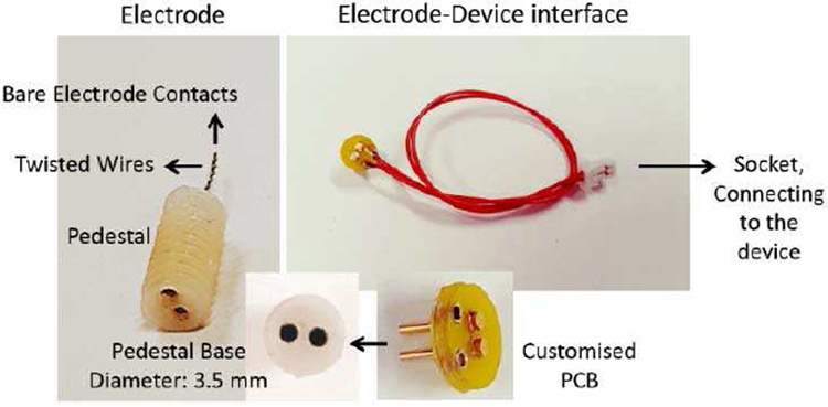
An electrode by PlasticsOne Inc (Roanoke, VA-USA) (Fig. 3), model MS303/2-B/SPC, is used in our in-vitro and in-vivo experiments. The electrode consists of two twisted and insulated stainless steel wires (0.2 mm bare electrode diameter, 0.23 mm insulated electrode diameter) connected to a pedestal.
Fig. 3.
PlasticsOne electrode, and customized electrode-device interface.
To provide access from the electrode pedestal to the input of the device, a customized circular printed circuit board (PCB) was designed (see Fig. 3). It has two pins for inserting into the electrode pedestal base. The customized PCB is then connected to the main device via two lead wires and a connector. The length of the lead wires is set to 10 cm for back-mountable electrode-device connection.
2). Analog Circuit:
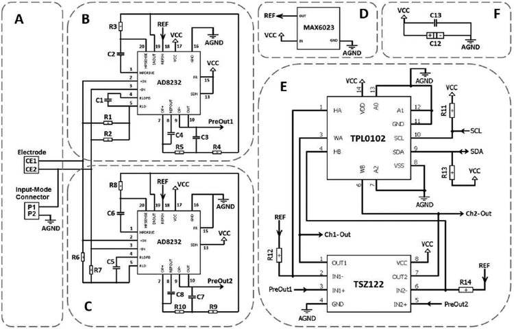
The neural signals are first obtained from the target brain region using the electrode (Fig. 4 (A)). The device can record the neural signals in two different configurations: differential, and single-ended. The selection of the differential or the single-ended recording is done through an input-mode jumper connector (Fig. 4 (A)). Leaving the connector open results in differential signal recording. In contrary, closing the connector using a jumper connector results in single-ended recording by grounding one of the electrode contacts.
Fig. 4.
Schematic diagram of the analog circuit. (A) Electrode and Input-mode connector mechanism. (B) Pre-amplifier, low-pass and high-pass filters for Channel 1. (C) Pre-amplifier, low-pass and high-pass filters for Channel 2. (D) Voltage reference generator. (E) Programmable amplifier for both Channels 1 and 2. (F) By-pass noise-reduction capacitors.
The analog circuit includes two channels: Ch1 as low-frequency channel, and Ch2 as high-frequency channel. In this design, AD8232 chip manufactured by Analog Devices is used in the first stage of both channels, see Fig. 4 (B-C). The AD8232 chip is a good option for extraction, amplification, and filtration of small bio-potential signals in the presence of noisy conditions. This is because it consists of an instrumentation amplifier (IA), an operational amplifier (OA), a right leg drive amplifier (RLD), and a reference buffer, all together inside the chip that can reduce the PCB space and power consumption compared with traditional implementations. Each input of the PlasticsOne electrode is coupled with the internal IA (of AD8232) which is set to provide pre-amplification with a gain of 100 V/V while simultaneously implementing a single-pole high-pass filter (HPF) for filtering out the unwanted lower frequencies. The HPF cut-off frequency of Ch1 is implemented at 7 Hz though C2 and R3 components (this value is at 200 Hz for Ch2 though C6 and R8 components). The cutoff frequency of the HPF is given equation (1).
| (1) |
In the current configuration, the RLD amplifier has been used to improve the common-mode rejection by maintaining the midscale voltage through R1 and R2 bias resistors (R6 and R7 in Ch2). The capacitor C1 (C5 in Ch2) between the RLDFB and RLD terminals creates an integrator. It has been included for common-mode line rejection of 50 Hz and its harmonies. The internal independent OA of AD8232 has been used to implement a two-pole low-pass filter (LPF) to remove additional high-frequency noise. For this purpose, the output of the IA from IAOUT terminal is connected to the input of the OA by means of a unity-gain Sallen-Key filter topology. The LPF cut-off frequency of Ch1 is at 45 Hz though R4, R5, C3, and C4 components (1 kHz for Ch2 through R9, R10, C7, and C8 components). As a common design procedure, we have set R4 = R5 and C3 = C4 (Ch2: R9 = R10 and C7 = C8), which results in the following relationship for LPF cutoff frequency:
| (2) |
AD8232 has a shutdown (SDN) control input terminal. In this application, we have permanently tied SDN to supply voltage (VCC) in order for circuit to always remain in the active mode. In addition, there is a fast restore (FR) control input terminal which reduces the duration of long settling tails for lower cut-off frequencies in the HPF. Because of the low cut-off frequency used in the HPF of CH1, neural signals may require several seconds to settle. This settling time can result in an unwanted delay after the electrode is connected. In order to avoid this long settling time, RF needs to be activated for Ch1 by permanently connecting the RF terminal to VCC. Because of the higher cut-off frequency used in the HPF of CH2, there is no need to use this mode and the RF terminal has been permanently tied to analog ground (AGND).
The last feature of the AD8232 chip is an embedded reference buffer, between the REFIN and REFOUT terminals, which simplifies the design of single-supply applications. This internal buffer is intended to create a virtual ground between the VCC and AGND. The signals present at the output of the IA are referenced to this voltage. Apart from creating an internal reference for IA, the buffer output voltage (accessed at REFOUT pin) is used as a reference in filtering. The reference voltage level is set at the buffer input terminal (REFIN pin) through a separate chip (Fig. 4 (D)), MAX6023EBT12, which is a reference voltage generator. MAX6023EBT12 manufactured by MAXIM is a precision, low-dropout, micro-power voltage reference chip that converts the 3V VCC input voltage to the 1.25 V reference output voltage. This chip is very small in size and does not require any external compensation capacitor. The generated reference voltage (REF) derives the REFIN pin of AD8232 in both Ch1 and Ch2 circuits.
After pre-amplification and filtration, the signals at the output of AD8232 chip (defined as PreOut 1 and PreOut 2 for Ch1 and Ch2, respectively; see Fig. 4 (B) and (C)) are directed to the next stage (Fig. 4 (E)) which is a programmable gain amplifier. In this stage, the programmability is attained by a combination of an OA with a digital potentiometer through a non-inverting amplifier topology. The generated reference voltage (REF) from the MAX6023 chip is consider to be a virtual ground for this stage. TSZ122, a dual version high precision zero drift micro-power chip, is used as OAs for both Ch1 and Ch2 signals. For each channel, a variable resistor is connected between the negative input and the output pins of the OA. A TPL0102 chip is employed as the digital potentiometer. It has two linear-taper digital potentiometers (A and B) with 256 wiper positions. Each variable resistor is used as a two-terminal rheostat between high and wiper terminals. The resistor values can change from 300Ω to 100 kΩ. The gain achieved is given by equation (3).
| (3) |
where Rv is the variable resistor and Rf is the fixed resistor between the reference voltage and the negative input of OA (R12 in Ch1, and R14 in Ch2). The fixed resistor is set to 100Ω. Therefore, by substituting the low and high values of the variable resistor into the formula, it can be seen that the gain in this stage can be adjusted between 4 to 1001 V/V. Assuming the pre-amplifier stage gain to be fixed 100 V/V, the total variable gain of 400 – 100100 V/V (∼ 50 – 100 dB) is accessible using the current design.
The digital potentiometer chip is controlled via the micro-controller in the digital part and is programmed using a physical bidirectional I2C interface involving the serial clock (SCL) and serial data (SDA) lines. Both SDA and SCL lines have been connected to VCC through pull-up resistors (R11 and R13). The unique device address given to the TPL0102 chip is 000 configured through A0 – A2 pins connected to AGND.
The amplified outputs of the final stage (identified as Ch1-Out and Ch2-Out) are directed to the microcontroller for digitization (see the next section). Two parallel capacitors (Fig. 4 (F)) are used as bypass between the VCC and AGND lines in order to minimize the noise on the power supply traces. The capacitor network includes a 100 nF ceramic capacitor (C13) in parallel to a 470 μF tantalum capacitor (C12). The former is intended for decoupling the power supplies. The latter is necessary to maintain stability. Although the analog circuit is designed to consume micro-power current range, the digital part including the microcontroller and the flash-memory drain reasonable amount of current from the battery when active. Therefore, to maintain stability of the circuit when sudden demand of current is needed, the use of C12 is unavoidable.
3). Digital Circuit:
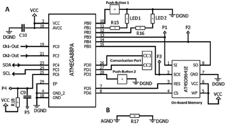
The main components of the digital circuit incudes a microcontroller (ATMEGA88PA), a serial flash-memory (AT45DB641E), LEDs, push-buttons, and communication port (see Fig. 5 (A)).
Fig. 5.
Schematic diagram of the digital circuit. (A) Digital circuit. (B) Analog and digital ground separation.
ATMEGA88PA is a high performance, low power 8-bit microcontroller. Its power consumption versus processing speed is optimizable via throughputs approaching 1 MIPS per MHz. In addition, it offers 16 KB of flash, 512 bytes of EEPROM, and 1 KB of internal SRAM. The chip supports C language compilers. The microcontroller does sampling and digitization of analog inputs (PC0 and PC2 pins) of Ch1 and Ch2 signals though the internal 10-bit ADC. The microcontroller also implements the programing of the digital potentiometer in the analog circuit using a physical bidirectional I2C interface involving the serial clock (SCL) and serial data (SDA) lines. Two LEDs are included into the device for recording (LED 1) and communication (LED 2) purposes. Each LED current is set via an external resistor (R15 and R16). In addition, two push-buttons are included in the device for user-device interaction purpose (Push-Button 1 for entering into the recording mode and Push-Button 2 for entering into the communication mode). In the recording mode, the device receives the analog data, digitizes and samples them, and then stores them on the serial flash-memory. In the communication mode, the device sends out data from the flash-memory using the embedded communication port. The microcontroller is programmed using P1 - P5 pads.
AT45DB641E is a 64-Mbit serial-interface sequential access flash-memory ideally suited for data storage applications. It operates from a single 1.7 - 3.6 V VCC for the erase, program, and read operations. It is enabled through the Chip Select pin (CS) and accessed via a 3-wire interface consisting of the Serial Input (SI), Serial Output (SO), and the Serial Clock (SCK). All programming and erase cycles are self-timed in the AT45DB641E chip.
The AGND and digital ground (DGND) parts have been separated from each other via a very low ohm resistor (Fig. 5 (B)). This method helps keep the possible digital noise out of the analog circuit.
4). Power Source:
The proposed device is a battery-operated system that can have its full functionality using a 2.5-3.5 V power source. A CR2032 coin battery (3V) has been used to supply power to both analog and digital circuits.
C. Fabrication
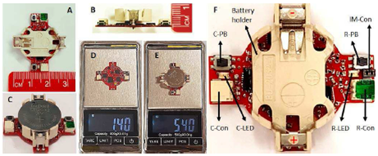
Fig. 6 shows the fabricated neural sensor, manufactured on a two-layer PCB. As shown in Fig. 6 (A-B), all the components are designed to sit on the top layer of the PCB. In addition, the device benefits from a circular configuration with 11 mm in radius and 8 mm in height (Fig. 6 (C-D)), allowing the PCB to be hidden under a 3V CR2032 coin battery holder (Fig. 6 (E)). As shown in Fig. 6 (F-G), the total weight of the device including CR2032 coin battery and battery holder is 5.4 g, in which only 1.4 g is for the neural sensor itself. Being small and light-weight allow back-mountable configuration for use with large or small laboratory animals.
Fig. 6.
(A) & (B) Device dimensions. (C) Complete device. (D) Weight of the device without the battery and battery holder. (E) Total weight of the complete device. (F) Operation features. C-PB: communication pushbutton, R-PB: recording push-button, C-Con: communication connector, RCon: recording connector, C-LED: communication LED, R-LED: recording LED, IM-Con: input-mode connector.
As indicated in Fig. 6 (H), there are two connector ports on the device, recording connector (R-Con) and communication connector (C-Con). The R-Con is for the electrode interface connection, and the C-Con is for connection to a computer. Moreover, two push-buttons are included on the device which are recording push-button (R-PB) and communication push-button (C-PB). The former is for starting/stopping the data writing into the flash-memory, and the latter is for starting/stopping of the data serial communication with an external computer. The recording LED (R-LED) and communication LED (C-LED) on each side of the device shows the operation function of the device to the user. The input-mode connector (IM-Con) allows the user to define whether the recording is single-ended or differential. Leaving IM-Con open will cause the device to record in differential mode. The input mode is switched from differential to single-ended via putting a small jumper connector that connects one electrode contacts to analog ground.
D. Software
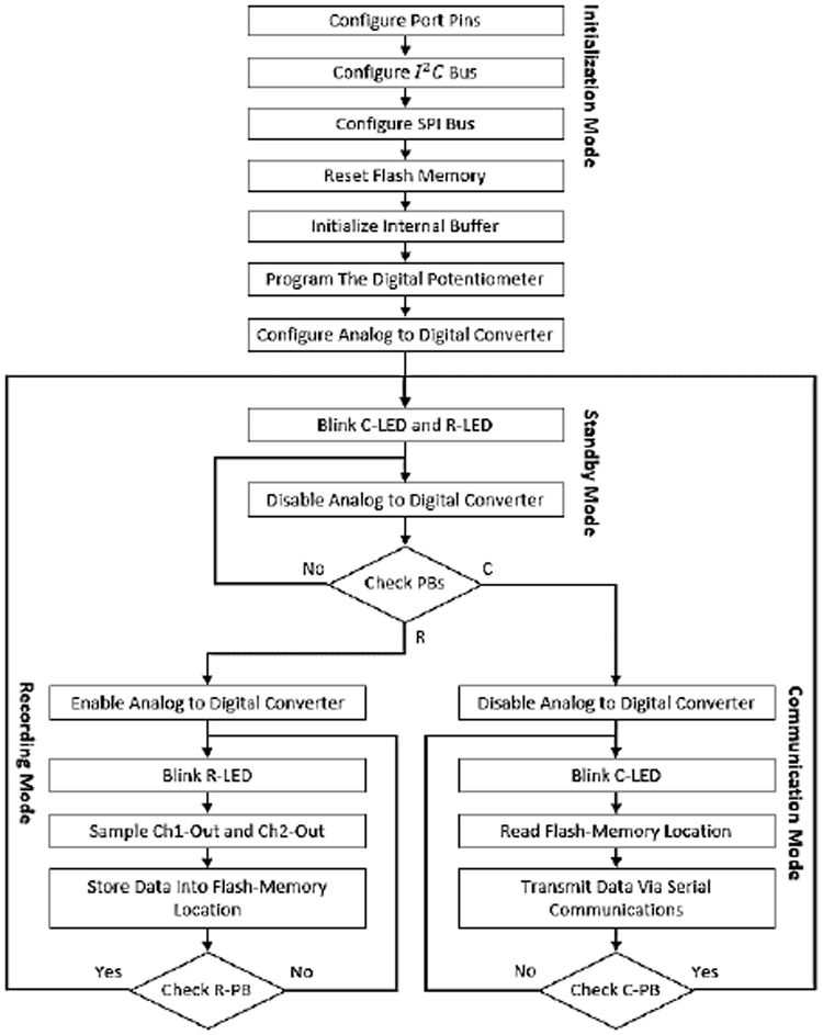
Fig. 7 depicts the flowchart diagram of the software module of the neural sensor. There are four different modes for the device which include: (1) Initialization mode, (2) Standby mode, (3) Recording Mode, and (4) Communication mode. Once the battery is placed into the device, the device enters the initialization mode in which the port pins, I^2 C and SPI buses, and the ADC are configured and the serial flash-memory is reset. In addition, the internal buffer is initialized and the digital potentiometer is programmed to a pre-specified gain of 78 dB.
Fig. 7.
Schematic diagram of the digital circuit. (A) Digital circuit. (B) Analog and digital ground separation.
Upon completion of the Initialization mode, both the LEDs blink to show that the device has entered into the Standby mode. In this mode, the ADC is disabled and both the push-buttons (R-PB and C-PB) are iteratively checked until any push-button (PB) is pressed. Whichever the PB is pressed, the device enters the associated mode: R for Recording and C for Communication.
In the Recording mode, the ADC is enabled and the neural data is sensed, and then sampled from the Ch1 and Ch2 outputs. This data is continuously stored in the serial flash-memory locations. The indication of this mode is fast blinks of R-LED. The device remains in this mode until the R-PB is pressed for the second time. If R-PB is pressed, the device enters the Standby mode and waits for the next user command.
In the Communication mode, the ADC is disabled and the flash-memory locations are continuously read. In addition, the data is transmitted to an external computer via the C-Con port. The indication of this mode is fast blinking of C-LED. The device stays in this mode until the data is fully transferred or the user has pressed C-PB for the second time. In this case, the device returns to the Standby mode and for the next recording/communication command.
E. Validations
The functionality of the proposed device has been validated through: (i) bench tests, (ii) in-vitro tests, and (iii) in-vivo tests. In the bench test validation, (i) sinusoidal and (ii) a pre-recorded neural signals are injected directly into the device inputs, and the outputs are compared with the original input signals. The in-vitro experiment has been conducted in saline solution which can simulate a neuron-electrode interface [46]. For this purpose, pre-recorded neural signals were injected into the saline solution and signals are then received by the electrode. The in-vivo test has been conducted on three 4 months old female mice. For this purpose, a single bipolar PlasticsOne electrode was implanted and subsequent, freelymoving recordings performed after recovery from surgery.
III. Experimental Results
A. Bench Tests and Results
The bench tests include: (i) measurements of the device frequency response, (ii) application of sinusoidal, and (iii) application of pre-recorded neural signals to the input of the neural sensor (in a single-ended configuration) and analysing the device output.
1). Frequency Response:
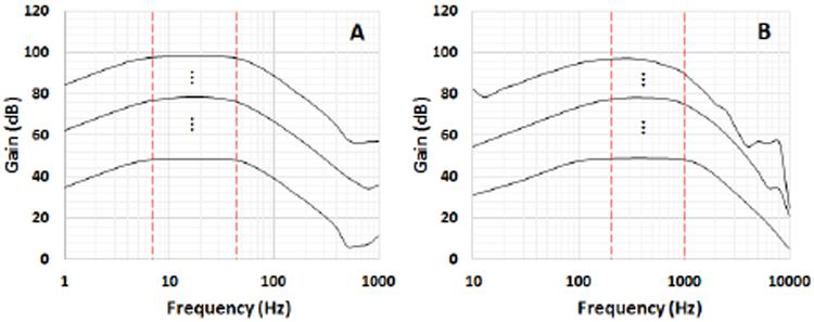
Fig. 8 illustrates the frequency response of both low-frequency (Ch1, Fig. 8 (A)) and high-frequency (Ch2, Fig. 8 (B)) channels obtained by using the NI myDAQ system and it’s bode plot software. The extracted data has been plotted in MATLAB software. The figure shows the minimum (∼50 dB), central (∼80 dB) and maximum (∼100 dB) gains accessible with the proposed device. It is worth mentioning that there are other 254 different programmable gain levels (linearly increasing) in between the minimum and maximum gain levels. The designed pass-band target is 7-45 Hz and 200-1000 Hz for Ch1 and Ch2, respectively (the red vertical lines show the target low and high cut-off frequencies). Due to the 0.1-10% tolerance of the resistors and capacitors used in the device, the real cut-off frequencies (−3 dB decrease from the maximum gain), have minor negligible deviations from their desired values.
Fig. 8.
Frequency response of the low-frequency (A) and high- frequency (B) channels.
2). Bench Test With Sinusoidal Signals:
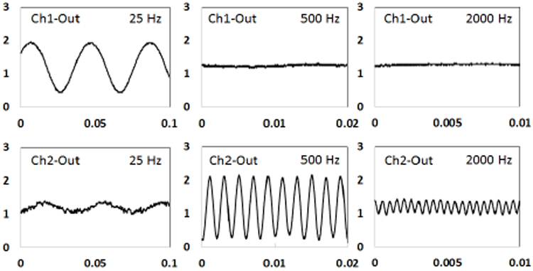
Three sinusoidal signals (200 μVpp) with three different frequencies (25 Hz, 500 Hz, and 2000 Hz) were directly injected into the input of the neural sensor (programmed with a gain of 78 dB). The resulted analog outputs at low and high-frequency channels (Ch1 and Ch2) are presented in Fig. 9. Because the 500 Hz and 2000 Hz frequencies are quite out of the Ch1 pass-band (> 40 dB), they have been totally filtered out in the outputs. Similarly, the 25 Hz and 2000 Hz signals have been reasonably attenuated in Ch2 due to being out of the Ch2 bandwidth. The reason for not being totally rejected is that these frequencies are approximately 15 dB lower than the maximum gain of Ch2. Therefore, they appear as an attenuated signal in the output.
Fig. 9.
Analog outputs resulted from a sinusoidal input signal (200 μVpp) with three different frequencies (25 Hz, 500 Hz, and 2000 Hz). The gain of was set to 78 dB. Values on the vertical axis represent the output amplitude in volt. Values on the horizontal axis resent time in in seconds.
Bench Test With Pre-Recorded Neural Signals:
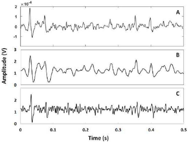
The final bench test involved the application of pre-recorded neural signals to the input of the device. The pre-recorded neural signals have been supplied by Prof. Benoit Gosselin of Laval University, Canada. They were captured from hippocampus of a 23 g mouse. The data includes a range of low- and high-frequency components up to 6 kHz and pick-to pick amplitude of 400 μV, recorded with a sampling frequency of 20 kS/s. This signal was sent out to the device by the arbitrary waveform generator (ARB) software of the NI myDAQ system through its analog output AO-0 with an update rate of 2 kHz. The bench test results, including the pre- (input to the device) and post- (output from the device) amplification signals, have been shown in Fig. 10 (A) for the input, and Fig. 10 (B-C) for Ch1 and Ch2 outputs, respectively. The gain of the device in both Ch1 and Ch2 have been programmed at around 78 dB (central gain). The results shown in Fig. 10 are related to the first 500 ms (out of 450 s) of the data. Since the input signal contains a range of low and high-frequency components over the pass-band range of both Ch1 and Ch2, the filters have attenuated the undesirable components, and the outputs have correctly mimicked the input signal in both Ch1 and Ch2
Fig. 10.
(A) Pre-recorded neural signal applied directly to the device in a single-ended configuration. (B) Ch1 output. (C) Ch2 output.
B. In-vitro Test and Results
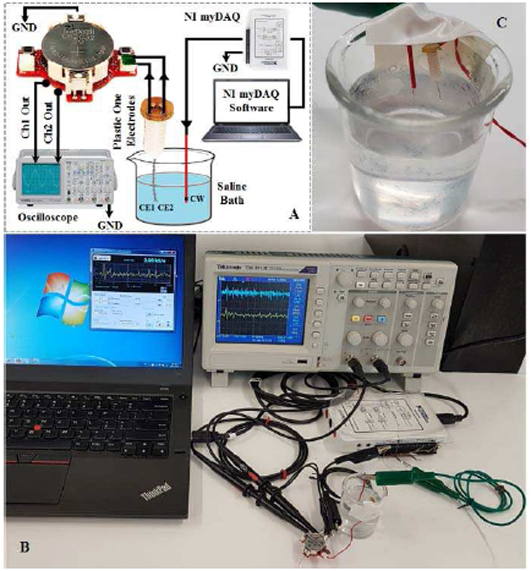
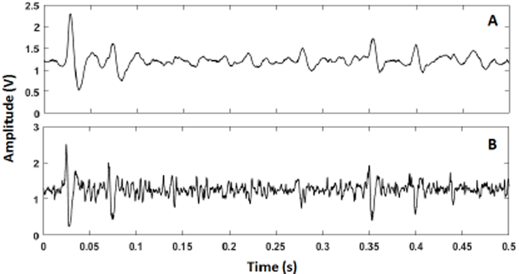
The in-vitro experiment has been conducted in saline solution that emulates the neuron-electrode interface [46]. The saline bath contains 0.9% NaCl per litter of distilled water. The setup used for the in-vitro saline-based experiment is presented in Fig. 11. A copper wire (CW) is employed to deliver the pre-recorded neural signals into the saline bath. The PlasticsOne electrode contacts (EC1 and EC2) collects the signal propagated in the solution, and delivers it to the device for conditioning. The recording is done in the single-ended configuration using the IM-CON option. The pre-recorded neural signal is injected into the saline solution with an update rate of 2 kS/s. The device collected the signal, digitized it, and stored it on its internal flash-memory. Next, the data is extracted from the flash-memory, sent to an external computer via the C-CON, and then plotted in MATLAB software. Fig. 12 shows the plotted Ch1-Out and Ch2-Out signals.
Fig. 11.
(A) Saline-based in-vitro setup model used to verify the Device. Ch1 and Ch2 outputs are connected to the analog output on the bottom layer of the PCB. (B) Experimental setting. (C) Electrode placement in saline solution. The red wire delivers the neural signal into the saline solution and the electrodes collects the signal in a single-ended configuration.
Fig. 12.
(A) Ch1 digital output sampled and stored in the memory from the in-vitro saline test. (B) Ch2 digital output sampled and stored in the memory from the in-vitro saline test.
The digital circuit implements the sampling frequency of about 16 kHz. However, because the ADC takes one sample from each channel sequentially at a time, each channel is thus sampled with a sampling frequency of about 8 kHz. As shown in Fig. 12, the Ch1 output follows the low-frequency variations of the input neural signal, while the Ch2 outputs retains the high- frequency variations of the signal. By comparison of these results (Fig. 12 (A) and (B)) with their counterparts obtained from the bench test with pre-recorded neural signals (Fig. 10), they seem to be compatible. The justification of the amplitude reduction is due to be the additional impedance in the signal path induced by the saline solution. This causes the attenuation of the signal before reaching the electrode. Nonetheless, it can be seen from Fig. 12 that the Ch1 and Ch2 outputs follow the low and high frequency fluctuations of the input signal.
C. In-vivo Test and Results
For in-vivo validation, three 4 months old C57Bl/6 female mice were implanted with electrodes and subsequently, freely-moving recordings were performed after recovery from surgery. The general procedure for surgery has been previously described in ref. [47]. Briefly, the mice were anesthetized with 2% isoflurane and placed in a supine position on a heating pad within a stereotaxic frame. A constant 2% isoflurane level was delivered throughout the surgery and adjusted according to each mouse’s breathing rate. Depilatory cream was applied to the head to remove all hair at the surgical site. After sterilizing the skin with alcohol and betadine, a single incision was made from just behind the eyes to the most posterior part of the occipital bone (all tools, including scissors FST#14082-09, #55 forceps FST #11255-20, Dumont AA forceps FST #11210-10, drill head for Ideal Micro-Drill™Surgical Drills #726065, drill bit FST#19007-05, were sterilized in a hot bead sterilizer before use). A small hole in the skull was drilled slightly posterior to the cranial suture. Carefully, a small skull screw (303 00-90 × 1/16 flat point stainless steel machine screw, B002SG89QQ) was screwed a few turns into the skull to serve as an anchor. The stereotaxic coordinates of Bregma were then used as a reference to locate three brain regions that are currently used as therapeutic targets for DBS: the dentate nucleus (cerebellum), medial globus pallidus (basal ganglia), and thalamus (ventral posterolateral nucleus). The coordinates as they relate to Bregma were shown in Table 1.
TABLE I.
The coordinates as they relate to bregma
| Cerebellum | Basal Ganglia |
Thalamus | |
|---|---|---|---|
| Anterior/Posterior | −6.0mm | −1.25mm | −1.7mm |
| Medial/Lateral | 2.25mm | 1.7mm | 1.8mm |
| Dorsal/Ventral (from the surface of the brain) | 2.15mm | 3.95mm | 3.25mm |
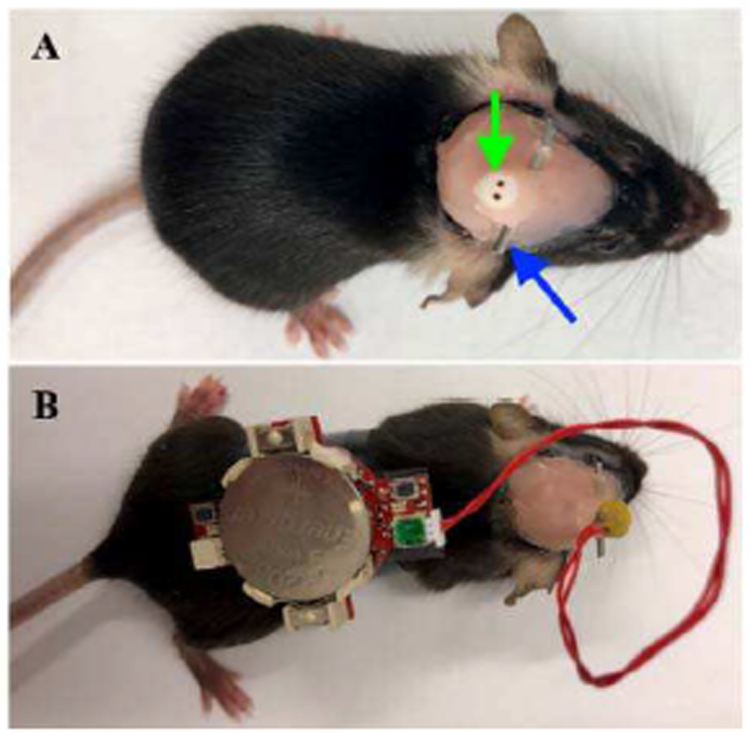
Next, a small 0.5 mm craniotomy was made and a single bipolar PlasticsOne electrode (#8IMS303T3B01, cut 3.5 mm below the pedestal; green arrow Fig. 13 (A)) was lowered to the appropriate depth according to the target desired. After carefully drying the area with a sterile cotton swab, one round of Metabond (4 drops of B Quick Base For C&B METABOND®mixed with 1 drop of "C" Universal TBB Catalyst, mixed with Metabond Clear L-Powder) followed by a layer of dental cement was used to secure the scalp screw and the electrode in its position and to cover all exposed skull. A ½-1 inch long cannula (stainless steel tube) was glued onto the protruding electrode to later serve as a head mount (blue arrow Fig. 13 (A)). This was secured with UV light epoxy and sealed with additional dental cement. Finally, 3M Vetbond (#NC0304169) was carefully applied around the border of dental cement and the mouse’s fur to better ensure the implant’s stability. The mice were provided with 0.75 mg/kg of buprenorphine (also provided pre-operatively) subcutaneously once a day for three days and allowed to recover post-surgery in a warmed incubator (V500, Peco Services Ltd., Cumbria, UK).
Fig. 13.
Tetherless recording in adult mouse.
In preparation for recording, the tetherless device was secured onto the back of a mouse (Fig. 13 (B)), making certain to leave the recording button accessible. The electrode-device interface was carefully plugged into the PlasticsOne electrode port by grasping the head mounted cannula for stability. After engaging the “record” button, the mouse was returned to its home cage and monitored for the entire duration of the neural recording session. All animal studies were performed under an approved IACUC protocol at Baylor College of Medicine.
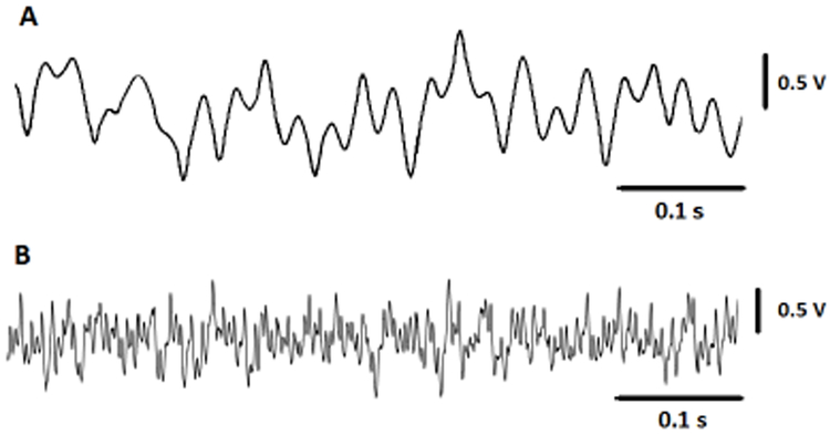
Fig. 14 shows the in-vivo results outputs from cerebellum, stored in the flash-memory of the neural sensor programmed with a gain of 70 dB. The presented signal in this figure represent a small portion of 8-minute recording of data.
Fig. 14.
(A) Small portion of neural signal recorded from the cerebellum region of a mouse, sampled at Ch1, and stored into the flash-memory. (B) Small portion of neural signal recorded from the cerebellum region of a mouse, sampled at Ch2 and stored into the flash-memory.
D. DBS Interference
One of the major limitations of the closed-loop DBS approach is the appearance of a large stimulation artefact (typically 100–120 dB larger than the neural activity [26]) on the neural recording path, making the simultaneous sensing and stimulation a challenge [48]. The neural recording circuit must be able to eliminate this large artefact from the weak neural signal in real-time for true biomarker measurements.
One of the techniques used to reject the stimulation artefact is the electrode configuration approach [48]. In this technique, the neural signals are sensed in a differential manner and the anode stimulation electrode is symmetrically placed between the recording electrodes [26, 48]. As a result, the stimulation pulse interference acts as a common-mode signal which can be cancelled in the first stage instrumentation amplifier.
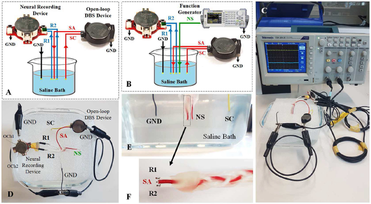
The performance of our neural sensor in cancelling the DBS has been tested in saline solution in two stages: (i) in the absence of neural source (Fig. 15 (A)), and (ii) in the presence of neural source (Fig. 15 (B)). The purpose of the first experiment is to examine the ability of the common-mode artefact cancellation of the neural sensor in reaction to the DBS pulses and in the absence of any neural signal source. The purpose of the second experiment is to examine the ability of the neural sensor in LFP source amplification in presence of a common-mode DBS artefact.
Fig. 15.
DBS schematic test setup in (A) the presence of stimulation pulse and (B) the presence of neural signal and stimulation pulse. (C) Real DBS test setup. (D) Top view of the saline bath connections. (E) Cross section of the saline bath electrode placements. (F) Close view of the recording and stimulation copper electrodes The SA electrode is adjusted to be placed in the center of the R1 and R2 electrodes with equal distances. R1 and R2: recording electrodes, SA: stimulation anode electrode, SC: stimulation cathode electrode, GND: common ground electrode, NS: neural source signal.
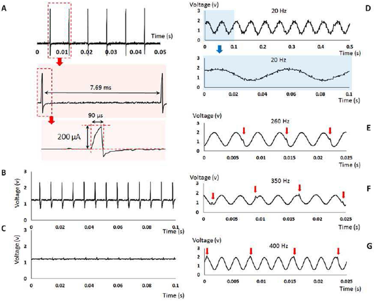
Fig. 15 (C-F) shows the physical saline-based setup used to evaluate the DBS interference. A three-contact symmetric wire copper electrode (Fig. 15 (F)) was used to represent the DBS lead. An open-loop DBS device was employed to generate the stimulation pulses with 200 μA current pulse amplitude, 130 Hz pulse frequency, and 90 μs pulse duration (as Fig. 16 (A)).
Fig. 16.
(A) The specifications of the stimulation pulses generated from an open-loop DBS device to test the neural sensor performance in terms of the reaction to the DBS interference. (B) The neural sensor analog output response to the stimulation pulses in absence of the neural source in the single-ended recording configuration. (C) The neural sensor analog output response to the stimulation pulses in absence of the neural source in the differential recording configuration. (D) The neural sensor analog output in response to the DBS 130 Hz interference and a 20 Hz sinusoidal input. (E) The neural sensor analog output in response to the DBS 130 Hz interference and a 260 Hz sinusoidal input. (F) The neural sensor analog output in response to the DBS 130 Hz interference and a 350 Hz sinusoidal input. (F) The neural sensor analog output in response to the DBS 130 Hz interference and a 400 Hz sinusoidal input.
The results obtained in the first experiment are shown in Fig. 16 (B) and (C) for the single-ended and differential recording configurations, respectively. In the single-ended recording configuration (measuring through one active electrode against the ground), the DBS pulses are not rejected, and appear as an amplified signal in the analog output of the neural sensor. However, using the differential recording configuration (measuring through two active electrodes), the DBS interference is attenuated around 24 dB in the output of the neural sensor compared to the single-ended recordings. The residual content of the stimulation pulse (as seen in Fig 16 (C)) is related to the potential tolerance in the distance of the middle stimulation anode electrode from the two recording electrodes manufactured manually. A small difference in the distance between the recording and stimulation electrodes causes the common-mode signal to have a slightly higher amplitude in one recording electrode compared to the second one. This amplitude difference is then amplified in the differential recording circuits, hence producing the slight disturbance in the signal. The use of commercial DBS lead will alleviate this issue.
The results obtained by the second setup in response to the several neural sources are shown in Fig. 16 (D-G). A sinusoidal signal with an amplitude of 1 mV is used to represent the neural signal source. The device is tested in response to four different frequencies 20 Hz, 260 Hz, 350 Hz, and 400 Hz as shown in Fig 16 (D)-(G). For the 20 Hz neural source, in which the frequency is lower than the 130 Hz stimulation pulse, the low-frequency analog output shows the attenuated DBS interference appearing as a very small artefact summed with the amplified 20 Hz neural signal source. Despite this small disturbance, it is seen that the device can reasonably amplify the neural signal in presence of a large common-mode stimulation artefact. For the 260 Hz, 350 Hz and 400 Hz neural sources, where the frequencies are higher than the 130 Hz stimulation pulse, the high-frequency analog output shows the attenuated DBS interference appearing as a very small artefact in only specific periods (specified with red arrows in Fig 16 (E-G)). For the 260 Hz input (twice of the 130 Hz DBS artefact), the stimulation disturbance appears once in every two periods, while for the 400 Hz input (∼three times of the 130 Hz DBS artefact) the stimulation disturbance appears once in every three periods. It should be noted that the amplitude of this artefact is very small compared to the amplified signal, and thus cannot affect the biomarker extraction and control process in a closed-loop DBS device. In addition, the use of a real DBS lead may help to reduce this residual content because of the precise symmetry between the recording and stimulation electrodes.
IV. Discussions
In our previous studies, we designed single [35] and multibiomarker-based [49] neural sensors that have a fixed gain amplifier. However, this paper presents the design of a multibiomarker (LFP and spikes) gain-programmable neural sensor, as well as its in-vivo validation. A comparison of the features of our device against those of some recent neural sensors [50-53] (within the last 3 years) is presented in Table II [50-54].
TABLE II.
Features of the developed device and some existing neural sensors.
| Specifications | Proposed device | Mitra et al.[50], 2015 | Irwin et al. [51], 2016 | IM et al. [52], 2016 | Kim et al. [53], 2017 | H.S. Kim and H.K. Cha [54], 2018 |
|---|---|---|---|---|---|---|
| Channels | 2 | 30 | 16 | 8 | 4×32 | 1 |
| GP | Yes | Yes | Yes | No | Yes | No |
| Gain Range | 50 – 100 dB | LFP: 35 – 50 dB, AP: 47 – 75 dB | 54 – 96 dB | 46 dB | 55 – 65 dB | 39.2 dB |
| Signal Band-width | 7 – 45 Hz and 200 – 1000 Hz | 0.5 – 500 Hz and 500 – 6000 Hz | Configurable cut-off frequencies in software (LPF: 0.1 – 500 Hz) – (HPF: 0.1–20kHz) | Programmable bandwidth (upper: 10 Hz – 20 kHz, lower: 0.02 Hz – 1 kHz) | HPF cut-off frequency: 18 – 154 Hz, LPF cut-off frequency: 5.8 kHz | 0.25 Hz to 28 kHz for a mixed of LFP and AP |
| Recording Method | US, single-ended or differential | Single-ended | Differential | Differential | Single-ended | Single-ended |
| DOPS | 3 V | NS | 3.7 V | 3.3 V | NS | 1.2 V |
| Battery Type, and Capacity | Li-ion, 240 mAh | Li-ion, 90 mAh | NS | Li-ion (wireless rechargeable), NS | NS | NS |
| Power Consumption | SM and CM: 3.3 mA, RM: 14.35 mA | Total: 2020 μW | 10.9 mW (681 μW per Ch) | NS | 62.5 μW/ch (8000 μW for 128 Ch) | 2.4 μW |
| Operation Time | Average: 24 h | 3 h | NS | NS | NS | NS |
| Dimension | 4.08 cm3 | 3.7 cm3 | NS, imaged as size of a dollar coin | 7.55 cm3 | NS, estimated: 17.9 mm2, based on die photograph | 0.09 mm2 |
| Weight | Total: 5.4 g | 7g | NS | 13.4 g | NS | NS |
| Sampling Frequency | 8 kHz | 1 kHz for LFP, 20 kHz for AP | 5 kHz – 40 kHz, subject to number of used channels | 200 Hz | 2.5 MHz | NS |
| On-board Memory | Yes | No, (has wireless transmission) | No | No (has wireless transmission) | No (has USB interface) | No |
| Application for DBS | Yes | No | No | No | Yes | No |
| Animal Test | Yes (mice) | No | Yes (monkey) | Yes (rat) | Yes (rat) | No |
| Electrode Type or Brand | PlasticsOne | NA | Percutaneous fine-wire electrodes | 8-Ch microarray electrode | NS | NA |
| Design Method | DC | ASIC | ASIC | DC | ASIC | ASIC |
GP: Gain Programmability, US: User Selectable, DOPS: Device Operating Power Supply, SM: Standby Mode, RM: Recording Mode, CM: Communication Mode, Ch: Channel, NS: not specified; NA: not applicable, DC: Discrete Components.
This device has a wide programmable gain range compared to other examined devices [50, 52, 53] (having fixed or limited gain variability) that offers the following advantage. In LFPs, the magnitude of the potentials can vary from as low as 10 μV to over 1 mV [55-57]. This wide range depends on several factors including: (i) proportional contribution of the multiple current sources within the brain [58], (ii) distance of the recording electrode from the current sources [58], (iii) sign of the individual current sources [58], (iv) different properties of the target brain tissue (e.g. resistivity and capacitance) [58, 59], (v) recording depth (cell type and the spatial distribution of synapses) [60], (vi) electrode characteristics (type, effective surface area, and conductivity) [61], (vii) subjects [58-60], and (viii) disease occurrence or a change on the brain state (e.g. LFP level change by seizure occurrence in Epileptic patients [62]). The LFP amplitude changing from 10 μV to 1 mV demands a neural sensor with a programmable gain that can change from at least 60 dB to 100 dB in order to amplify the varying potentials to at least 1 V. Therefore, the application of a fixed gain or limited-range programmable-gain neural sensor (see Table II) will be quite limited. Our device has a programmable gain from 50 dB to 100 dB over the required range, which makes it a general-purpose neural sensor.
The proposed neural sensor is a battery-operated device working with voltages within the range 2.5 V to 3.5 V. These requirements led us to choose a 3V CR2032 coin battery (capacity: 240 mAh) for the operation of the device. The device can operate in four different modes (Initialization, Standby, Recording, and Communication) each consuming different current levels from the operated battery. The current consumption of the device in the Initialization, Standby, and Communication modes is about 3.3 mA. The current consumption increases to 14.35 mA in the Recording mode. While the device benefits from an onboard 64 Mbit flash-memory, the memory is included to store in-vivo brain signals for offline processing and validation of the sensing function of the device. The memory feature might not however be required when the device is integrated into a closed-loop DBS system and on-line processings is required. Accordingly, the average operation time of the device on a CR2032 coin battery would be approximately 75 hours.
This device has been designed using discrete components instead of the application-specific integrated circuits (ASIC) approach. While an ASIC is more compact in size, its design and development is very time consuming and expensive. Thus, the ASIC design approach is more suitable for human-based applications rather than animal-based trials when lower costs and faster design process are important [63] Although our device has been designed based on discrete components, it benefits from a miniature physical size, and low weight. The board has a surface area of 5.1 cm2, volume: 4.08 cm3, and weight of 5.4 g including the coin battery and battery holder. The device can easily fit in a rat jacket to conduct back-mountable free-moving pre-clinical experiments with laboratory animals such as rats, pigs, etc. Although our device might not be the smallest available neural sensing system, it is very low-cost, and can sense both at single-ended and differential modes, has a wide-range programmable gain. The proposed device dioe snot offer a wireless data transfer feature. Adding a wireless module, such as a bluetooth low energy (BLE) device, will increase the power consumption, weight, and size of the device.
Finally, the performance of the proposed device was validated via: (i) bench tests though direct connection of sinusoidal and pre-recorded signals to the input of the device, (ii) in-vitro testl in saline solution, and (iii) in-vivo test on three 4 months old female mice. In addition, the performance of the neural sensor in cancelling the DBS artefact is also tested in saline solution in two stages: (i) in the absence of neural source, and (ii) in the presence of neural source. The device successfully passed these experiments, and it is ready to be used in a closed-loop DBS platform. This device senses, amplifies and filters two specific frequency bands comprising six biomarkers (alpha, beta, slow gamma, slow high-frequency oscillations, fast high-frequency oscillations, and spikes). A feature extraction algorithm and a control strategy will be deployed into the microcontroller to create closed-loop operation. The computing capability of the microcontroller is suitable for implementation of simple feature extraction and control algorithms in an iterative manner in the closed-loop DBS setting. However, the use of a more advanced microcontroller is suggested if more complex processing is required where the overall power consumption of the device in not a concern.
V. CONCLUSION
In this paper, a neural sensor was presented which is capable of simultaneously measuring LFPs and spikes, digitizing the measured signals, storing them into an on-board flash-memory, and transferring them to an external computer. The device is a programmable, miniature (radius: 11 mm), lightweight (5.6 g including battery), tetherless, and self-contained. The performance of the device was validated through bench tests (using sinusoidal and pre-recorded neural signals), in-vitro test (using saline solution as a simulator of brain environment), and in-vivo test (brain of three female mice) tests. The results obtained through these tests indicate the successful neural sensing performance. Two further experimens were conducted to study the role of the DBS intereference. The results show the attenuation of the DBS artefact to around 24 dB through the differential compared to the single-ended recording configuration. The results confirm the device suitability for the future integration into a closed-loop DBS system.
Acknowledgments
This work was supported by funds from Baylor College of Medicine (BCM) and Texas Children’s Hospital, BCM IDDRC Grant U54HD083092 from the Eunice Kennedy Shriver National Institute of Child Health and Human Development (Neuropathology Sub-Cores), and by National Institutes of Neurological Disorders and Stroke (NINDS) R01NS089664 and R01NS100874.
Biographies

Mahboubeh Parastarfeizabadi received the B.Sc. and M.Sc. degrees in biomedical engineering from Azad University and University of Isfahan, Iran, in 2010 and 2013, respectively. She is currently a final year Ph.D. student with the School of Engineering at Deakin University, Australia. Her research interests include medical microsystems, deep brain stimulation, biomedical signal processing in particular EEG, LFP and spikes, bio-instruments and implants, neurofeedback and biofeedback trainings. She was awarded the Deakin University Postgraduate Research Scholarship in 2015.

Abbas Z. Kouzani (M’95) received the B.Sc. degree in computer engineering from Sharif University of Technology, Iran, the M.Sc. degree in electrical and electronics engineering from the University of Adelaide, and the Ph.D. degree in electrical and electronics engineering from Flinders University, Australia. He was a Lecturer with the School of Engineering, Deakin University, and a Senior Lecturer with the School of Electrical Engineering and Computer Sci-ence, University of Newcastle, Australia. Currently, he is a Professor with the School of Engineering at Deakin University. He has been involved in about $15 million research grants, and has published over 330 papers. He served as the Associate Head of School (Research) with the School of Engineering, Deakin University, for several years. He is an OzReader with the Australian Research Council. He has carried out applied research and consultancy for over 25 Australian and international companies. His current research interests include medical/biological microsystems, microfluidic lab-on-a-chip devices, bioinstruments, biosensors, and implants. He is the director of Deakin University’s Advanced Integrated Microsystems (AIM) Research Group.

Jaclyn Beckinghausen received a B.Sc. degree in biology from The College at Brockport, Brockport, New York in 2014. Currently, she is a second year Neuroscience Ph.D. student at Baylor College of Medicine in Houston, Texas. Her graduate research involves molecular biology and anatomy, optogenetic manipulation, deep brain stimulation, and in vivo single unit extracellular recordings in mouse models of dystonia.

Tao Lin received B.Sc. and M.Sc. degrees in biology from Xiamen University, China, and a Ph.D. degree in biomedical science from Texas A&M University, USA. He is a research associate at Baylor College of Medicine and Texas Children’s Hospital. His research interests involve cerebellar function and disease.

Roy V. Sillitoe received a B.Sc. in Kinesiology from Simon Fraser University, Burnaby, British Columbia, Canada and a Ph.D. in Neuroscience from the University of Calgary, Calgary, Alberta, Canada. He is an Associate Professor in the Departments of Pathology & Immunology and Neuroscience at Baylor College of Medicine (BCM). He is the Co-Director of the Graduate Program in Developmental Biology at BCM and he is the Director of the BCM IDDRC Neurovisualization Core, which is part of an NIH funded facility. His research interests include neural development, genetics, optogenetics, in vivo electrophysiology, and behavioral paradigms. He uses the mouse cerebellum as a model system for studying motor and non-motor diseases. His research is supported by multiple NIH grants.
Footnotes
We thank Prof. Benoit Gosselin and Dr. Masoud Rezaei from Laval University, Canada, for providing us with pre-recorded neural signals for bench and in-vitro saline tests.
REFERENCES
- [1].Parastarfeizabadi M and Kouzani AZ, "Advances in closed-loop deep brain stimulation devices," Journal of NeuroEngineering and Rehabilitation, vol. 14, p. 79, August 11 2017. [DOI] [PMC free article] [PubMed] [Google Scholar]
- [2].Arlotti M, Rosa M, Marceglia S, Barbieri S, and Priori A, "The adaptive deep brain stimulation challenge," Parkinsonism & Related Disorders, vol. 28, pp. 12–17, 2016. [DOI] [PubMed] [Google Scholar]
- [3].Neumann WJ, Huebl J, Brucke C, Gabriels L, Bajbouj M, Merkl A, et al. , "Different patterns of local field potentials from limbic DBS targets in patients with major depressive and obsessive compulsive disorder," Mol Psychiatry, vol. 19, pp. 1186–1192, 2014. [DOI] [PMC free article] [PubMed] [Google Scholar]
- [4].Thevathasan W, Pogosyan A, Hyam JA, Jenkinson N, Foltynie T, Limousin P, et al. , "Alpha oscillations in the pedunculopontine nucleus correlate with gait performance in parkinsonism," Brain, vol. 135, pp. 148–160, 2012. [DOI] [PMC free article] [PubMed] [Google Scholar]
- [5].Priori A, Foffani G, Pesenti A, Tamma F, Bianchi AM, Pellegrini M, et al. , "Rhythm-specific pharmacological modulation of subthalamic activity in Parkinson’s disease," Exp Neurol, vol. 189, pp. 369–79, October 2004. [DOI] [PubMed] [Google Scholar]
- [6].Eusebio A, Thevathasan W, Doyle Gaynor L, Pogosyan A, Bye E, Foltynie T, et al. , "Deep brain stimulation can suppress pathological synchronisation in parkinsonian patients," Journal of Neurology, Neuro-surgery & Psychiatry, vol. 82, pp. 569–573, 2011. [DOI] [PMC free article] [PubMed] [Google Scholar]
- [7].Kühn AA, Tsui A, Aziz T, Ray N, Brücke C, Kupsch A, et al. , "Pathological synchronisation in the subthalamic nucleus of patients with Parkinson’s disease relates to both bradykinesia and rigidity," Experimental Neurology, vol. 215, pp. 380–387, 2009. [DOI] [PubMed] [Google Scholar]
- [8].Toledo JB, López-Azcárate J, Garcia-Garcia D, Guridi J, Valen-cia M, Artieda J, et al. , "High beta activity in the subthalamic nucleus and freezing of gait in Parkinson’s disease," Neurobiology of Disease, vol. 64, pp. 60–65, 2014. [DOI] [PubMed] [Google Scholar]
- [9].Little S and Brown P, "What brain signals are suitable for feedback control of deep brain stimulation in Parkinson’s disease?," Ann N Y Acad Sci, vol. 1265, pp. 9–24, 2012. [DOI] [PMC free article] [PubMed] [Google Scholar]
- [10].Little S, Pogosyan A, Neal S, Zavala B, Zrinzo L, Hariz M, et al. , "Adaptive deep brain stimulation in advanced Parkinson disease," Annals Of Neurology, vol. 74, pp. 449–457, 2013. [DOI] [PMC free article] [PubMed] [Google Scholar]
- [11].Rosa M, Arlotti M, Ardolino G, Cogiamanian F, Marceglia S, Di Fonzo A, et al. , "Adaptive deep brain stimulation in a freely moving Parkinsonian patient," Mov Disord, vol. 30, pp. 1003–5, June 2015. [DOI] [PMC free article] [PubMed] [Google Scholar]
- [12].Maling N, Hashemiyoon R, Foote KD, Okun MS, and Sanchez JC, "Increased Thalamic Gamma Band Activity Correlates with Symptom Relief following Deep Brain Stimulation in Humans with Tourette’s Syndrome," PLOS ONE, vol. 7, p. e44215, 2012. [DOI] [PMC free article] [PubMed] [Google Scholar]
- [13].Beudel M, Little S, Pogosyan A, Ashkan K, Foltynie T, Limousin P, et al. , "Tremor Reduction by Deep Brain Stimulation Is Associated With Gamma Power Suppression in Parkinson’s Disease," Neuromodulation, vol. 18, pp. 349–354, 2015. [DOI] [PMC free article] [PubMed] [Google Scholar]
- [14].Bragin A, Engel J Jr., Wilson CL, Fried I, and Buzsaki G, "High-frequency oscillations in human brain," Hippocampus, vol. 9, pp. 137–42, 1999. [DOI] [PubMed] [Google Scholar]
- [15].Worrell G and Gotman J, "High-frequency oscillations and other electrophysiological biomarkers of epilepsy: clinical studies," Biomark Med, vol. 5, pp. 557–66, October 2011. [DOI] [PMC free article] [PubMed] [Google Scholar]
- [16].Assenza G, Capone F, di Biase L, Ferreri F, Florio L, Guerra A, et al. , "Oscillatory Activities in Neurological Disorders of Elderly: Biomarkers to Target for Neuromodulation," Frontiers in Aging Neuroscience, vol. 9, 2017-June-13 2017. [DOI] [PMC free article] [PubMed] [Google Scholar]
- [17].Zijlmans M, Jiruska P, Zelmann R, Leijten FS, Jefferys JG, and Gotman J, "High-frequency oscillations as a new biomarker in epilepsy," Ann Neurol, vol. 71, pp. 169–78, February 2012. [DOI] [PMC free article] [PubMed] [Google Scholar]
- [18].Foffani G, Priori A, Egidi M, Rampini P, Tamma F, Caputo E, et al. , "300-Hz subthalamic oscillations in Parkinson’s disease," Brain, vol. 126, pp. 2153–63, October 2003. [DOI] [PubMed] [Google Scholar]
- [19].Foffani G and Priori A, "Deep brain stimulation in Parkinson’s disease can mimic the 300 Hz subthalamic rhythm," Brain, vol. 129, p. e59; author reply e60, December 2006. [DOI] [PubMed] [Google Scholar]
- [20].Lopez-Azcarate J, Tainta M, Rodriguez-Oroz MC, Valencia M, Gonzalez R, Guridi J, et al. , "Coupling between beta and high-frequency activity in the human subthalamic nucleus may be a pathophysiological mechanism in Parkinson’s disease," J Neurosci, vol. 30, pp. 6667–77, May 12 2010. [DOI] [PMC free article] [PubMed] [Google Scholar]
- [21].Danish SF, Moyer JT, Finkel LH, Baltuch GH, Jaggi JL, Priori A, et al. , "High-frequency oscillations (>200 Hz) in the human non-parkinsonian subthalamic nucleus," Brain Res Bull, vol. 74, pp. 84–90, September 14 2007. [DOI] [PubMed] [Google Scholar]
- [22].Özkurt TE, Butz M, Homburger M, Elben S, Vesper J, Wojtecki L, et al. , "High frequency oscillations in the subthalamic nucleus: A neurophysiological marker of the motor state in Parkinson’s disease," Experimental Neurology, vol. 229, pp. 324–331, 2011. [DOI] [PubMed] [Google Scholar]
- [23].Wang J, Hirschmann J, Elben S, Hartmann CJ, Vesper J, Wojtecki L, et al. , "High-frequency oscillations in Parkinson’s disease: Spatial distribution and clinical relevance," Movement Disorders, vol. 29, pp. 1265–1272, 2014. [DOI] [PubMed] [Google Scholar]
- [24].Jongwoo L, Hyo-Gyuem R, Kipke DR, and Flynn MP, "A 64 Channel Programmable Closed-Loop Neurostimulator With 8 Channel Neural Amplifier and Logarithmic ADC," Solid-State Circuits, IEEE Journal of, vol. 45, pp. 1935–1945, 2010. [Google Scholar]
- [25].Weiss SA, Alvarado-Rojas C, Bragin A, Behnke E, Fields T, Fried I, et al. , "Ictal onset patterns of local field potentials, high frequency oscillations, and unit activity in human mesial temporal lobe epilepsy," Epilepsia, vol. 57, pp. 111–21, January 2016. [DOI] [PMC free article] [PubMed] [Google Scholar]
- [26].Stanslaski S, Afshar P, Peng C, Giftakis J, Stypulkowski P, Carlson D, et al. , "Design and Validation of a Fully Implantable, Chronic, Closed-Loop Neuromodulation Device With Concurrent Sensing and Stimulation," Neural Systems and Rehabilitation Engineering, IEEE Transactions on, vol. 20, pp. 410–421, 2012. [DOI] [PubMed] [Google Scholar]
- [27].Azin M, Guggenmos DJ, Barbay S, Nudo RJ, and Mohseni P, "A Battery-Powered Activity-Dependent Intracortical Microstimulation IC for Brain-Machine-Brain Interface," Solid-State Circuits, IEEE Journal of, vol. 46, pp. 731–745, 2011. [Google Scholar]
- [28].Pinnell RC, Dempster J, and Pratt J, "Miniature wireless recording and stimulation system for rodent behavioural testing," J Neural Eng, vol. 12, p. 066015, October 15 2015. [DOI] [PubMed] [Google Scholar]
- [29].Arlotti M, Rossi L, Rosa M, Marceglia S, and Priori A, "An external portable device for adaptive deep brain stimulation (aDBS) clinical research in advanced Parkinson’s Disease," Med Eng Phys, vol. 38, pp. 498–505, May 2016. [DOI] [PubMed] [Google Scholar]
- [30].Hyo-Gyuem R, Jaehun J, Fredenburg JA, Dodani S, Patil PG, and Flynn MP, "A Fully Self-Contained Logarithmic Closed-Loop Deep Brain Stimulation SoC With Wireless Telemetry and Wireless Power Management," Solid-State Circuits, IEEE Journal of, vol. 49, pp. 2213–2227, 2014. [Google Scholar]
- [31].Chang SY, Kimble CJ, Kim I, Paek SB, Kressin KR, Boesche JB, et al. , "Development of the Mayo Investigational Neuromodulation Control System: toward a closed-loop electrochemical feedback system for deep brain stimulation," J Neurosurg, vol. 119, pp. 1556–65, 2013. [DOI] [PMC free article] [PubMed] [Google Scholar]
- [32].Bledsoe Jonathan M., Kimble Christopher J., Covey Daniel P., Blaha Charles D., Agnesi Filippo, Mohseni Pedram, et al. , "Development of the Wireless Instantaneous Neurotransmitter Concentration System for intraoperative neurochemical monitoring using fast-scan cyclic voltammetry," Journal of Neurosurgery, vol. 111, pp. 712–723, 2009. [DOI] [PMC free article] [PubMed] [Google Scholar]
- [33].Abdelhalim K, Jafari HM, Kokarovtseva L, Perez Velazquez JL, and Genov R, "64-Channel UWB Wireless Neural Vector Analyzer SOC With a Closed-Loop Phase Synchrony-Triggered Neurostimulator," Solid-State Circuits, IEEE Journal of, vol. 48, pp. 2494–2510, 2013. [Google Scholar]
- [34].Abdelhalim K, Jafari HM, Kokarovtseva L, Velazquez JLP, and Genov R, "64-Channel UWB wireless neural vector analyzer and phase synchrony-triggered stimulator SoC," in ESSCIRC (ESSCIRC), 2012 Proceedings of the, 2012, pp. 281–284. [Google Scholar]
- [35].Parastarfeizabadi M, Kouzani AZ, Gibson I, and Tye SJ, "A miniature closed-loop deep brain stimulation device," in 2016 38th Annual International Conference of the IEEE Engineering in Medicine and Biology Society (EMBC), 2016, pp. 1786–1789. [DOI] [PubMed] [Google Scholar]
- [36].Jankovic J, "Parkinson’s disease: clinical features and diagnosis," Journal of Neurology, Neurosurgery & Psychiatry, vol. 79, pp. 368–376, 2008. [DOI] [PubMed] [Google Scholar]
- [37].Rivlin-Etzion M, Marmor O, Heimer G, Raz A, Nini A, and Bergman H, "Basal ganglia oscillations and pathophysiology of movement disorders," Curr Opin Neurobiol, vol. 16, pp. 629–37, December 2006. [DOI] [PubMed] [Google Scholar]
- [38].Johnson LA, Nebeck SD, Muralidharan A, Johnson MD, Baker KB, and Vitek JL, "Closed-Loop Deep Brain Stimulation Effects on Parkinsonian Motor Symptoms in a Non-Human Primate - Is Beta Enough?," Brain Stimul, vol. 9, pp. 892–896, Nov-Dec 2016. [DOI] [PMC free article] [PubMed] [Google Scholar]
- [39].Morishita T and Inoue T, "Need for multiple biomarkers to adjust parameters of closed-loop deep brain stimulation for Parkinson’s disease," Neural Regeneration Research, vol. 12, pp. 747–748, May/15/accepted 2017. [DOI] [PMC free article] [PubMed] [Google Scholar]
- [40].Engel AK and Fries P, "Beta-band oscillations—signalling the status quo?," Current Opinion in Neurobiology, vol. 20, pp. 156–165, 2010/April/01/ 2010. [DOI] [PubMed] [Google Scholar]
- [41].Gleason CA, Kaula NF, Hricak H, Schmidt RA, and Tanagho EA, "The effect of magnetic resonance imagers on implanted neurostimulators," Pacing Clin Electrophysiol, vol. 15, pp. 81–94, January 1992. [DOI] [PubMed] [Google Scholar]
- [42].Shellock FG, Magnetic resonance safety update 2002: Implants and devices. [DOI] [PubMed] [Google Scholar]
- [43].Kuncel AM and Grill WM, "Selection of stimulus parameters for deep brain stimulation," Clinical Neurophysiology, vol. 115, pp. 2431–2441, 2004. [DOI] [PubMed] [Google Scholar]
- [44].Rossi L, Foffani G, Marceglia S, Bracchi F, Barbieri S, and Priori A, "An electronic device for artefact suppression in human local field potential recordings during deep brain stimulation," J Neural Eng, vol. 4, pp. 96–106, 2007. [DOI] [PubMed] [Google Scholar]
- [45].Al-ani T, Cazettes F, Palfi S, and Lefaucheur JP, "Automatic removal of high-amplitude stimulus artefact from neuronal signal recorded in the subthalamic nucleus," J Neurosci Methods, vol. 198, pp. 135–46, May 15 2011. [DOI] [PubMed] [Google Scholar]
- [46].Chaturvedi V and Amrutur B, "An Area-Efficient Noise-Adaptive Neural Amplifier in 130 nm CMOS Technology," IEEE Journal on Emerging and Selected Topics in Circuits and Systems, vol. 1, pp. 536–545, 2011. [Google Scholar]
- [47].White JJ, Lin T, Brown AM, Arancillo M, Lackey EP, Stay TL, et al. , "An optimized surgical approach for obtaining stable extracellular single-unit recordings from the cerebellum of head-fixed behaving mice," Journal of Neuroscience Methods, vol. 262, pp. 21–31, 2016. [DOI] [PMC free article] [PubMed] [Google Scholar]
- [48].Zhou A, Johnson BC, and Muller R, "Toward true closed-loop neuromodulation: artifact-free recording during stimulation," Current Opinion in Neurobiology, vol. 50, pp. 119–127, 2018/June/01/ 2018. [DOI] [PubMed] [Google Scholar]
- [49].Parastarfeizabadi M and Kouzani AZ, "A Miniature Low-Power Multi-Biomarker-Based Brain Sensor for Closed-Loop DBS," IEEE Sensors Journal, vol. 17, pp. 3109–3115, 2017. [Google Scholar]
- [50].Mitra S, Putzeys J, Lopez CM, Pennartz CMA, and Yazicioglu RF, "24 Channel dual-band wireless neural recorder with activitydependent power consumption," Analog Integrated Circuits and Signal Processing, vol. 83, pp. 317–329, 2015. [Google Scholar]
- [51].Irwin ZT, Thompson DE, Schroeder KE, Tat DM, Hassani A, Bullard AJ, et al. , "Enabling Low-Power, Multi-Modal Neural Interfaces Through a Common, Low-Bandwidth Feature Space," IEEE Transactions on Neural Systems and Rehabilitation Engineering, vol. 24, pp. 521–531, 2016. [DOI] [PubMed] [Google Scholar]
- [52].Im C, Koh CS, Park HY, Shin J, Jun S, Jung HH, et al. , "Development of wireless neural interface system," Biomedical Engineering Letters, vol. 6, pp. 164–171, 2016. [Google Scholar]
- [53].Kim S, Na S-I, Yang Y, Kim H, Kim T, Cho JS, et al. , "A 4×32-Channel Neural Recording System for Deep Brain Stimulation Systems," JOURNAL OF SEMICONDUCTOR TECHNOLOGY AND SCIENCE, vol. 17, pp. 129–140, 2017. [Google Scholar]
- [54].Kim HS and Cha H-K, "A Low-Noise Biopotential CMOS Amplifier IC Using Low-Power Two-Stage OTA for Neural Recording Applications," Journal of Circuits, Systems and Computers, vol. 27, p. 1850068, 2018. [Google Scholar]
- [55].Hoof C. v. and Yoo H-J, Bio-medical CMOS ICs: New York: : Springer Verlag, 2011, 2011. [Google Scholar]
- [56].Bagheri A, Salam MT, Perez Velazquez JL, and Genov R, "Low-Frequency Noise and Offset Rejection in DC-Coupled Neural Amplifiers: A Review and Digitally-Assisted Design Tutorial," IEEE Trans Biomed Circuits Syst,June 10 2016. [DOI] [PubMed] [Google Scholar]
- [57].Ng KA, Greenwald E, Xu YP, and Thakor NV, "Implantable neurotechnologies: a review of integrated circuit neural amplifiers," Medical & Biological Engineering & Computing, vol. 54, pp. 45–62, 2016. [DOI] [PMC free article] [PubMed] [Google Scholar]
- [58].Buzsaki G, Anastassiou CA, and Koch C, "The origin of extracellular fields and currents–EEG, ECoG, LFP and spikes," Nat Rev Neurosci, vol. 13, pp. 407–20, 2012. [DOI] [PMC free article] [PubMed] [Google Scholar]
- [59].Pettersen KH and Einevoll GT, "Amplitude Variability and Extracellular Low-Pass Filtering of Neuronal Spikes," Biophysical Journal, vol. 94, pp. 784–802, 2008. [DOI] [PMC free article] [PubMed] [Google Scholar]
- [60].Lindén H, Tetzlaff T, Potjans Tobias C., Pettersen Klas H., Grün S, Diesmann M, et al. , "Modeling the Spatial Reach of the LFP," Neuron, vol. 72, pp. 859–872, 2011. [DOI] [PubMed] [Google Scholar]
- [61].Obien MEJ, Deligkaris K, Bullmann T, Bakkum DJ, and Frey U, "Revealing neuronal function through microelectrode array recordings," Frontiers in Neuroscience, vol. 8, p. 423, 2014. [DOI] [PMC free article] [PubMed] [Google Scholar]
- [62].Pais-Vieira M, Yadav AP, Moreira D, Guggenmos D, Santos A, Lebedev M, et al. , "A Closed Loop Brain-machine Interface for Epilepsy Control Using Dorsal Column Electrical Stimulation," Scientific Reports, vol. 6, p. 32814, 2016. [DOI] [PMC free article] [PubMed] [Google Scholar]
- [63].Angotzi GN, Boi F, Zordan S, Bonfanti A, and Vato A, "A programmable closed-loop recording and stimulating wireless system for behaving small laboratory animals," Sci. Rep, vol. 4, 2014. [DOI] [PMC free article] [PubMed] [Google Scholar]


