Abstract
The shape of a concentric tube robot depends not only on the relative rotations and translations of its constituent tubes, but also on the history of relative tube displacements. Existing mechanics-based models neglect all history-dependent phenomena with the result that when calibrated on experimental data collected over a robot’s workspace, the maximum tip position error can exceed 8 mm for a 200-mm-long robot. In this paper, we develop a model that computes the bounding kinematic solutions in which Coulomb friction is acting either to maximize or minimize the relative twisting between each pair of contacting tubes. The path histories associated with these limiting cases correspond to first performing all tube translations and then performing relative tube rotations of sufficient angle so that the maximum Coulomb friction force is obtained along the interface of each contacting tube pair. The robot tip configurations produced by these path histories are shown experimentally to bound position error with respect to the estimated frictionless model compared to path histories comprised of translation or mixed translation and rotation. Intertube friction forces and torques are computed as proportional to the intertube contact forces. To compute these contact forces, the standard zero-clearance assumption that constrains the concentrically combined tubes to possess the same centerline is relaxed. The effects of clearance and friction are explored through numerical and physical experiments and it is shown that friction can explain much of the prediction error observed in existing models. This model is not intended for real-time control, but rather for path planning—to provide error bounds and to inform how the ordering of tube rotations and translations can be used to reduce the effect of friction.
Keywords: Concentric tube robots, friction, model calibration, tube clearance
I. Introduction
CONCENTRIC tube robots are being applied to many types of medical interventions including surgery inside the heart [1]–[4], the brain [5], [6], and the lungs [7]–[9]. Many of these implementations have employed a mechanics-based kinematic model derived from the Cosserat rod model [10], [11] or a potential energy formulation [12], [13]. While the resulting kinematic model is more complex than standard robot models, real-time implementations have been successfully demonstrated [5]. The model does neglect some physical phenomena, however, resulting in larger kinematic model errors than is desirable for medical applications. For example, the reported mean and maximum tip position errors were 4.2 and 8.3 mm for a 207-mm-long robot [10] and 2.89 and 8.49 mm for a 200-mm-long robot [11]. Since targeting errors of 1–2 mm can be significant in surgeries performed near critical structures, these are large modeling errors. To compensate, image-based feedback is often needed, necessitating a higher skill level on the part of the operator.
A particular shortcoming of current models is that they do not include the effect of path history on robot shape, as shown in Fig. 1. To investigate how much of the unmodeled behavior may be due to friction, this paper formulates a mechanics-based model of tube-on-tube Coulomb friction by deriving expressions for the distributed contact forces between the tubes. The goal of this paper is develop bounds on the effect of friction on the kinematic solution. Such a model can be used in path planning and can motivate potential future work incorporating path history in real-time control. To reduce model complexity, a number of simplifications are made as described in the paragraphs below.
Fig. 1.
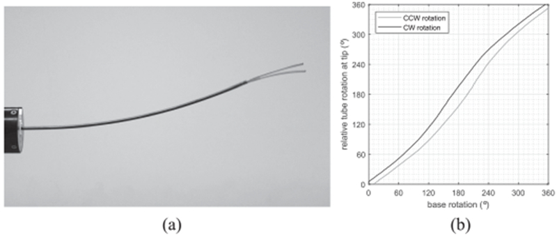
Path dependence of concentric tube pair. (a) Superimposed photographs of robot shapes achieved by clockwise and counterclockwise rotation for a base angle of 120°. (b) Relative tube rotation angle at tip versus base.
Small nonzero clearances between tubes:
The frictionless model assumes that all overlapping tubes conform to a single centerline curve, which implies that there is no clearance between tubes. In reality, however, a finite clearance must be used, i.e., a small gap must exist between the outer diameter of the inner tube and the inner diameter of the outer tube. If this clearance is too small, the tubes bind up and cannot be rotated and translated. It is necessary to include clearance in the model in order to compute the distribution and magnitude of the intertube contact forces. Prior work on friction modeling did not include intertube clearance and consequently only provided an approximate solution [14]. As formulated in this paper, however, clearances are assumed to be small (empirically, up to 2% of the minimum radius of tube curvature is acceptable).
Coulomb friction is assumed:
We assume that torsional and translational friction between the tubes is purely due to Coulomb friction. The Coulomb friction force FC for unidirectional sliding at velocity v is given by [15]
| (1) |
in which FN is the normal force of contact and μ is the friction coefficient. This model assumes that at zero velocity (i.e., the case considered in this paper), friction produces the minimum force sufficient to resist motion up to the limit of ±μFN. For tube-on-tube friction, the clearance model is used to compute the normal contact force.
Only tube twisting due to friction is modeled:
We neglect any effect of friction through relative tube translation on tube bending, longitudinal compression, and tube buckling. Neglect of bending is justified based on experimental observation as shown in Section V-B. Longitudinal rigidity is an assumption of the frictionless model.
We solve for limiting solutions in which Coulomb friction either maximizes or minimizes the relative twist between contacting tube pairs:
An actual robot path is comprised of tube rotations and translations that can vary in direction and magnitude. For these arbitrary path histories, the intertube friction force acting at any particular arc length along a tube pair may lie “inside the friction cone” since Coulomb friction generates the minimum force necessary to prevent motion. In the most general case, one would need to model the propagation of slip with arc length as pairs of tubes are rotated. Furthermore, even if tubes are considered longitudinally rigid, tube translation will reduce frictional torsion since a component of the friction force will be directed longitudinally. To reduce overall modeling complexity, these effects are neglected.
The contribution of this paper is to derive a model that provides estimates of the maximum error introduced by friction at any point in joint space. The model assumes that a configuration in joint space is reached by first translating all tubes and then performing relative tube rotations of sufficient magnitude prior to reaching the goal configuration that the maximum Coulomb torque is applied along the entire arc length of each contacting tube pair. This approach provides a set of solutions corresponding to positive and negative rotations for each contacting tube pair. We show experimentally that these solutions provide estimates of the maximum error introduced by friction.
The model is derived using a convex optimization approach that solves for intertube contact and friction forces by considering the clearance between tubes. Additional assumptions used are that tube cross sections are circular and no external forces are applied. The formulation for the intertube contact minimizes elastic potential energy while allowing each tube’s centerline curve to vary within the clearances of its inner and outer neighbors. This paper extends the results of [16] by incorporating friction forces and torques in the derivations and numerical experiments and by reporting physical experiments supporting the clearance and friction models. In addition, this paper provides more rigorous mathematical formulations compared to [16] of the Jacobian matrices that transform curvature changes to centerlines changes and body frame rotations.
While not related to concentric tube robots, there is a literature on friction modeling that considers some of the same issues. For example, the mechanisms literature considers the modeling of joints with clearance and friction [17]. In the robotic steering of needles through soft tissue, friction between the needle and tissue can generate torsional twisting of the needle [18]. In the analysis of tendon-driven continuum robots, the modeling of tendon friction has received considerable attention [19]–[22].
The paper is organized as follows. The kinematics in the presence of tube clearances are derived in Section II as an optimization problem. The following section introduces Coulomb friction into the model. Section IV presents a set of numerical experiments to investigate the effect of the clearance and friction on robot shape and intertube contact forces. Next, a set of physical experiments validating the tube clearance and the friction models are described. Conclusions are presented in Section VI.
II. Incorporating Tube Clearance
This section derives a kinematic model for concentric tube robots that incorporates the tube-to-tube clearance. The standard zero-clearance model is first reviewed in which all the tubes conform to a single centerline curve. Then the kinematics in the presence of clearance are formulated as an energy minimization by relaxing the single centerline assumption. An energy minimization is solved through a vector space optimization and its dual problem formulation. Finally the computational algorithms to solve the dual problem are presented. The variables used in the paper are enumerated in the Nomenclature. We remark that vectors are expressed with bold lower case letters, matrices are denoted by bold uppercase letters, and functions and scalar variables are denoted by either lower or uppercase nonbold italic letters.
A. Standard Zero-Clearance Kinematics
Consider a concentric tube robot with n tubes. The robot is parameterized with an arc-length parameter s along the length. The tubes are numbered from the outermost one (tube 1) to the innermost one (tube n). Tube i has its own precurvature function and bending and torsional stiffness . The x- and y-components of ûi(s) represent the bending curvature and the z-component represents the twist rate of the tube (e.g., rad/mm).
The existing mechanics-based kinematic model provides an elastic equilibrium of the tubes. The kinematics can be mathematically summarized as a map from base rotations and translations to the bending curvatures and torsional curvatures (twist rates) of the tubes [10], [11]:
-
1)
input: (θb, lb)
-
2)
output: ui(s) for s ∈ [li,b, li,e] and i = 1, …, n
where and are the base rotations and translations of the tubes, respectively, and is the 3-D curvature function of tube i at the elastic equilibrium whose x- and y-components are the bending curvature, z-component is the torsional curvature, and s = li,e is the distal end of tube i. The body frames and the centerline curves of the tubes Ri(s) and pi(s) are then computed from ui(s) by
| (2) |
with the boundary conditions
| (3) |
where êz = [0 0 1]T and the upper dot represents the derivative with respect to s. Note that 〈·〉 is the 3 × 3 skew symmetric matrix representation of 3-D vector and is the rotation matrix of the frame rotated by θ about z-axis from I3×3. The solution of the kinematics satisfies pi(s) = pj(s) for any tube i and tube j since this is one of the simplifying assumptions used in [10]–[13]. The computation of ui(s) involves solving a set of differential equations, the details of which can be found in [10] and [11].
B. Kinematics in the Presence of Clearance
When there are clearances between tubes, the centerlines of the tubes can vary up to the limits prescribed by the clearances. Employing a potential energy formulation as in [12] and [13] and relaxing the assumption of a shared centerline, the mechanics of the tubes with nonzero clearances can be expressed as an infinite-dimensional optimization as follows:
| (4) |
where
| (5) |
subject to the contact constraints, i.e., each tube must remain inside its outer neighbor. Here, Ki is a 3 × 3 diagonal matrix with ki,xy, ki,xy, and ki,z in the diagonal components.
C. Formulation as Vector Space Optimization
The optimization in the previous section can be converted to a vector space optimization by discretizing the arc length s and all functions of s. First, let vector and vector denote the collection of discretized ui(s) and pi(s), i.e,
| (6) |
and define vectors and , the collections of and vector for all the tubes, as
| (7) |
Here, {sij}j=1,…,Ni is the set of all the discretized points on tube i and Ni is the number of the points. To define them, the entire robot length is discretized first and then {sij}j=1,…,Ni is formed as the collection of all discretized points where tube i exists. Defining Si = {sij}j=1,…,Ni as the set of points for tube i, we note that S1 ⊂ S2 ⊂ ⋯ ⊂ Sn since inner tubes are longer and so are defined over a larger range of arc length than outer tubes. N is defined as the sum of Ni over all tubes, i.e., . Then, by (2) and (3), is a function of , i.e.,
| (8) |
The contact constraint can also be expressed as a set of inequalities imposed on a function of the vector . For now, let us just write it by
| (9) |
The numerical integration of the objective in (4) is also rewritten with the vector of the form
| (10) |
where is the discretized precurvature vectorized from in the same way as and is a diagonal matrix whose ith diagonal component is the bending or torsional stiffness (× arc length step) associated with the ith component of the curvature vector u. For example, the first and the second diagonal components of K are k1,xyΔs and the third component is k1,zΔs, where Δs is the step size in the arc-length discretization. Note that the torsional stiffness of tube i, ki,z, is computed by ki,z = ki,xy/(1 + ν), where ki,xy and ν are the bending stiffness and the Poisson’s ratio, respectively. The energy function (10) thus is the potential energy of all the tubes induced by both bending and twist.
Despite the convex objective function, this problem is not convex because the contact constraint is nonconvex. By assuming small clearances and, accordingly, small differences in the tube curvatures from the solution of the zero-clearance model introduced at the beginning of Section II, the optimization reduces to a convex problem by linearizing (8).
Let denote an initial guess of the solution about which the system will be linearized. The solution of the zero-clearance model, for example, can be considered as the initial guess. Let , and denote the discretized version of this solution following the notation of (6) and (7). Define and as the small changes in the curvatures and the centerlines from the initial guess as follows:
| (11) |
Substituting (11) in the objective (10) and omitting the constant term yields
| (12) |
where g is defined by
| (13) |
Now let us focus on the contact constraint. Consider the cross section of the robot at pi(s) as shown in Fig. 2. The cross section intersects with pi+1(s + ϵ), not pi+1(s), since integrating along the different centerlines results in different arc lengths on the cross section. The quantity ϵ is this arc-length difference. While we assume the tubes have circular cross sections, the intersection of the inner tube with the cross-sectional plane of the outer tube in Fig. 2(b) would not be a circle since the the tubes are angles from each other. However, it is still possible to approximate it as a circle based on the small clearance assumption. The constraint can then be written as
| (14) |
where the clearance ci(i = 1, …, n) is given by
| (15) |
where ri,in and ri,out are the inner and outer radii of tube i, respectively.
Fig. 2.
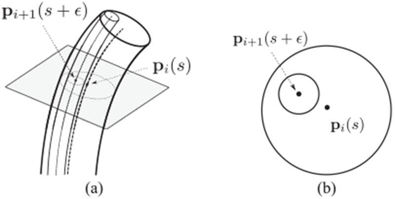
Intersection of inner tube with cross section of outer tube. (a) Centerlines. (b) Plane of cross section.
Assuming small ϵ, the first-order approximation of pi(s) − pi+1(s + ϵ) is given by
| (16) |
Since (16) is a vector on the cross-sectional plane, the projection of this vector onto the plane is the vector itself, shown as follows:
| (17) |
where the projection matrix is approximated with , i.e.,
| (18) |
Noting that is a small vector since for small clearances and is a null vector of Pi(s), the last term on the right side of (17) is a second-order term. Neglecting this term, the contact constraint (14) reduces to
| (19) |
This inequality needs to be evaluated on the discretized points where both tube i and tube i + 1 exist. This can be done by substituting s = sij into (19) and the resulting inequality can be now expressed with the vector of the form
| (20) |
for all i = 1, …, n − 1, j = 1, …, Ni where is a selection matrix to pick pi (sij) and −pi+1(sij) from such that
| (21) |
and is a projection matrix given by
| (22) |
Linearizing (8) in terms of and ,
| (23) |
where . The matrix Jp maps small changes in tube curvatures to the corresponding changes in the tube centerlines. The analytic form of Jp is presented in Appendix B. Finally, the constraint (20) can be expressed as a convex constraint with respect to by combining (20) with and from (11) and (23), as follows:
| (24) |
where Xij, xij, and qij are given by
| (25) |
Now the problem consists of a convex objective function and a set of convex constraints. This is, however, computationally difficult to solve using a standard iterative optimization involving gradient descent and projection onto the constraint manifold owing to the high dimensionality of and the large number of nonlinear constraints. For this reason, we recast the problem as its dual [23] to reduce its dimensionality and produce linear constraints.
D. Dual Problem Formulation
The dual problem involves optimizing over Lagrange multipliers associated with the constraints of the original problem. The dimensionality of the dual problem is thus equal to the number of constraints in the original problem. The dual problem is a maximization and its objective function is always concave while the constraints are linear since the multipliers are nonnegative. For example, the three-tube robot design appearing later in the paper is of dimension 630 and involves 133 nonlinear constraints when the innermost tube is fully extended. In its dual formulation, the dimensionality is reduced to 133 with 133 linear constraints. Furthermore, it has been shown that the dual problem attains the global solution of the original problem if the original problem was convex [23].
Following [23], the dual problem is given as the following maximization:
| (26) |
subject to
| (27) |
where λ = [λ1 λ2 …]T is an M-dimensional vector and M is the number of constraints, i.e., . Q(λ) and h(λ) are defined as
| (28) |
| (29) |
where Xk and xk are renumbered with the index k from Xij and xij, respectively. The gradient of Eλ is then analytically given by
| (30) |
where Gk is renumbered from Gij in (24) and is given by
| (31) |
This can be computed by solving the linear equation
| (32) |
for a given Q and h. An efficient way of solving this equation using the matrix inversion lemma is given in Appendix A.
Gradient ascent with constraint projection works nicely with this problem thanks to the linear constraints (27). The projection of λ onto the violated constraints can be done simply by setting all λk < 0 to be λk = 0
Physically, these multipliers are proportional to the contact forces concentrated at the corresponding points. The force can be derived as
| (33) |
based on a virtual displacement and energy analysis. Here, ci is the clearance of the tube pair associated with the kth contact constraint. Note that, since we have discretized the arc length, distributed contact forces are computed as sets of neighboring concentrated forces.
E. Computation of Clearance Model
The algorithm to solve the dual problem optimization is as follows. Given an initial guess , the initialization steps include:
-
1)
constructing matrix K based on the stiffnesses of the tubes,
-
2)
computing g from (13),
-
3)
computing Jp as given in Appendix B,
-
4)
computing qk(=qij), and from (25),
-
5)
initializing λ.
The optimization loop is as follows:
-
1)
Compute Q and h from (28) and (29) using the current values of λ
-
2)
Solve for .
-
3)
Compute in (30) using computed in 2).
-
4)
Update λ by λ ← λ + δd with a small positive scalar δ.
-
5)
For all k, set λk = 0 if λk < 0.
-
6)
Check convergence and terminate the loop if converged.
-
7)
Otherwise, go back to 1).
The convergence can be checked based on the change in λk between two consecutive iterations. Once converged, the latest can be added to to compute the new tube curvatures. A good initial guess can be given from the standard zero-clearance model. Recalling that the tube centerline change is assumed linear to by (23), the solution obtained through this optimization is an approximation. The solution can then be refined by substituting itself as a new initial guess and running the optimization loop again. This can be implemented as an outer loop that encloses the optimization loop as an inner loop. The computational steps of the outer loop are given below:
-
1)
Set as the solution of the standard zero-clearance model.
-
2)
Compute through the above optimization for given .
-
3)
Terminate the loop if is small, i.e., for a small positive γ.
-
4)
Update by for a positive real α.
- 5)
For the three-tube robot design used in the simulat ions and experiments, the values of δ, α, and γ are chosen to be δ = 10−3, α = 1.0, and γ = 10−6 for stable convergence. The inner loop usually runs for hundreds to thousands of iterations and the outer loop runs for tens of iterations. The initial λk was chosen as a positive constant, such as λ = [1, 1, 1, …]T, and then the final λ in the previous optimization loop is used as the initial λ in the following loop.
III. Modeling Maximum Torsional Friction
We now seek to model the configurations in which intertube friction either maximizes or minimizes the relative angular twist between tube pairs. To do so, we assume that the path history is such that Coulomb friction is producing its maximum force at each point of contact along the length of the tube pairs (i.e., the friction coefficient multiplied by the local normal force) and that this force is entirely directed so as to oppose tube twisting (i.e., there is no component in the direction of translation).
With friction, the system is no longer conservative and so its model cannot be formulated directly by energy minimization. We can, however, introduce friction into the model derived above. Consider that the dual problem in Section II-D can be interpreted as solving for equilibrium of a mechanical system of elastic rods under interaction forces between tubes. To see this, substitute (11), (13), (25), (28), and (29) into (32), which yields
| (34) |
where
| (35) |
| (36) |
Here fnormal,k is the normal force applied on the outer tube associated with the kth contact constraint, whose magnitude becomes fk in (33) once λ converges. Then in (35) applies this force on both the inner and outer tubes with the opposing directions. Note that fnormal is a vector comprised of the forces applied on all the discretized points of the tubes and the left side of (34) is a vector comprised of all the elastic moments on the same set of points. In a robotics context, (34) is an equation of static equilibrium between the elastic moments of the tubes and the normal forces on the tubes [24].
Our goal in this section is to reformulate the equilibrium (34) to include the tube-to-tube friction forces and torques in the form
| (37) |
so as to solve for the equilibrium in the presence of the friction. Here f is a vector comprised of forces that include both the normal contact forces and the friction forces, τ is a vector of the friction torques and Jω is a Jacobian matrix of Ri(s) with respect to derived in Appendix B. Physically the Jacobian matrix Jω is the linear map from small changes in tube curvatures to the corresponding angular displacements in the tube body frames. This formulation leads to new forms of Q(λ) and h(λ) different from (28) and (29).
Noting that Jp is the differentiation of F in (8), Jp transforms body-frame curvature changes to world-frame centerline changes. Thus, the force vector f is to be expressed in the world frame. The Jacobian matrix Jω is derived in Appendix B to convert body-frame curvature changes to body-frame rotations of the frames Ri(s). Consequently, the torque vector τ is to be expressed in the body frame.
Now, the force f and the torque τ will be derived accordingly. Focusing on the kth contact constraint, the friction force lies on the plane perpendicular to the normal force fnormal,k. Assuming that the entirety of the friction force is directed toward tube twisting, the friction force can be computed by the cross product of the tangent vector of the tube centerline and the normal force fnormal,k. Assuming that the path history is such that the maximum friction force magnitude is being applied at each point of contact, its magnitude is proportional to fnormal,k with the friction coefficient μk. Finally, the friction force is expressed as
| (38) |
where is an approximation of the tangent vector of the outer tube (tube i) given by the initial solution, sk (= sij) is where the kth contact constraint is defined, and ηk decides the direction of the friction force depending on the prior relative base rotation between the tubes associated with the kth contact constraint. Here, ηk is defined as
| (39) |
where counterclockwise (CCW) and clockwise (CW) rotations are defined by the inner tube rotation relative to the outer tube. Again, the bracket 〈·〉 in (38) indicates the 3 × 3 skew symmetric matrix.
Adding this friction force to (35) yields
| (40) |
Now the body-frame expression of the friction torques will be given. Since the friction torques are applied about the tube’s central axis, i.e., the z-axis of Ri(s), the body-frame expression of the torque is simply the z-vector êz = [0 0 1]T multiplied with a scalar that represents the magnitude of the torque. The torque magnitude is computed as a multiplication of the contact force magnitude, the friction coefficient, and the tube radius. Using the scalar representation of the contact force in (33), the friction torques on the outer and inner tubes are given respectively by
| (41) |
where fk is defined in (33) and ηk decides the direction again based on the relative tube rotation. The collection of τk,in and τk,out over all k = 1, …, M is given by
| (42) |
where Wk is given by
| (43) |
where the ith and i + 1st diagonal blocks are nonzero matrices, Wi,k = ηkri,inμkI3Ni×3Ni and Wi+1,k = ηkri+1,outμkI3Ni+1×3Ni+1 and all the others are zero matrices, i.e., Wj,k = 03Nj×Nj for j ≠ i, i + 1. Here, i and i + 1 are the indices of the tubes involved in the kth contact constraint.
By substituting (40) and (42) into (37) and after an algebraic manipulation, the moment equilibrium (37) reduces again to
| (44) |
for new Q(λ) and h(λ) given by
| (45) |
| (46) |
where
| (47) |
Equation (44) is the same form with (34) but Q(λ) and h(λ) are now in different forms. Replacing (28) and (29) with (45) and (46) in the algorithm of Section II-E results in the solution that incorporates friction. In the inner loop initialization, as a result, Jω as well as Jp needs to be computed and and are replaced with and , respectively.
IV. Numerical Experiments
To understand how clearance and friction influence robot kinematics and contact force distribution, two designs of concentric tube robots were investigated in a series of numerical experiments: 1) a balanced tube pair and 2) a three-tube robot. Tube parameters are given in Tables I and II.
TABLE I.
Parameters of Tube Pair
| Tube 1 | Tube 2 | ||
|---|---|---|---|
| Section 1 | Section 1 | Section 2 | |
| Length (mm) | 150 | 17 | 150 |
| Curvature (mm−1) | 1/150 | 0.0 | 1/150 |
| Bending Stiffness (Nm2) | 5.07 × 10⁻² | 5.07 × 10⁻² | |
| Poisson’s ratio | 0.3 | 0.3 | |
| OD \ ID (mm) | –\1.02 - 7.0 | 1.0\– | |
| Clearance (mm) | 0.01 - 3.0 | ||
| Friction coefficient | 0.0 - 0.5 | ||
TABLE II.
Parameters of Three-Tube Robot
| Tube 1 | Tube 2 | Tube 3 | |||
|---|---|---|---|---|---|
| Section 1 | Section 1 | Section 2 | Section 1 | Section 2 | |
| Length (mm) | 150 | 17 | 150 | 184 | 86.4 |
| Curvature (mm−1) | 1/265 | 0.0 | 1/265 | 0.0 | 1/55 |
| Bending Stiffness (Nm2) | 5.07 × 10⁻² | 5.07 × 10⁻² | 1.45 × 10⁻² | ||
| Poisson’s ratio | 0.3 | 0.3 | 0.3 | ||
| OD \ ID (mm) | –\2.39 | 2.305\1.95 | 1.825\– | ||
| Clearance (mm) | 0.0425 | 0.0625 | |||
| Friction Coefficient | 0.2 | 0.2 | |||
Note that the analysis is independent of the outer diameter (oD) of the outermost tube (tube 1) and the inner diameter (ID) of the innermost tube (tube n). These parameters are marked as “–” in the tables.
The tubes for each design are shown in Fig. 3. The collars shown at the proximal ends of the tubes are required to mount the tubes in the drive system and have a length of 17 mm. The constraints introduced by the collars are included in the analysis. While any integration method can be used, the results presented here were computed using Euler integration, which implies that the discretized values are interpolated as constant between adjacent discretized points.
Fig. 3.
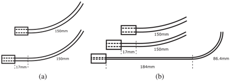
Robot designs comprised of (a) a tube pair and (b) three tubes. The dashed lines indicate boundaries between straight and curved tube sections.
A. Effect of Clearance and Friction on Tip Position
Using the tube pair, we first investigated the effect of clearance alone on robot tip position, where tip position is measured for the inner robot tube. Fig. 4 compares the tip position computed for five values of clearance with the position predicted by the standard zero-clearance model. The difference in tip position is plotted as a function of base rotation angle. Tip position difference tends to increase with increasing clearance and base rotation, with the maximum differences occurring for values less than 180°. This is a more accurate result than was reported in [16], where the linearization (23) was performed only once.
Fig. 4.
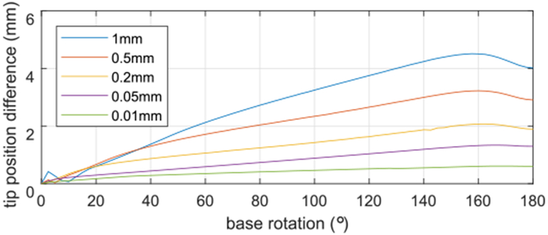
Difference in tip position compared to zero-clearance model. The curves are plotted for 5° increments of the base rotation.
We note that the nonsmooth portions of the curves at small base rotation angles, magnified in Fig. 5, are due to the mounting collars. This effect is explained below in Section IV-B.
Fig. 5.
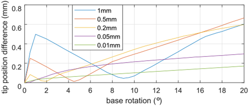
Difference in tip position compared to zero-clearance model for small values of base rotation angle. The curves are plotted for 0.5° increments of the base rotation.
While reducing clearance increases the accuracy of the zero-clearance model, it can be anticipated that the effect of friction between the tubes will be larger for smaller clearances. This is demonstrated in Fig. 6 which depicts tip position difference as a function of clearance for a tube pair base angle of 180° considering five values of friction coefficient.
Fig. 6.
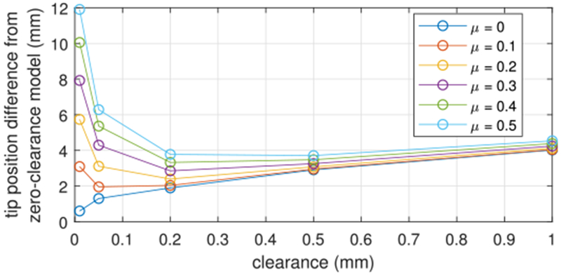
Difference in tip position compared to zero-clearance model for a tube pair base angle of 180° as a function of clearance and friction coefficient.
Fig. 7 graphically illustrates how tip position varies with clearance and friction coefficient. In the depicted configuration, the zero-clearance frictionless model would predict the tubes to be straight along their entire length. With clearance, however, the tip moves in the direction of the outer tube curvature as the clearance increases. This is due to the mounting collars as explained in the following section. Friction produces tip displacements in the perpendicular direction. This is due to the fact that friction reduces rotation of the tubes along their length. As expected, the small clearance case is more influenced by the friction.
Fig. 7.
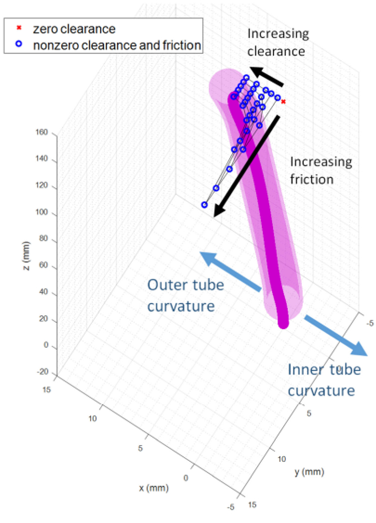
Tip position of a tube pair as a function of clearance and friction coefficient. Base rotation angle is 180°. The illustrated tube shapes are for a clearance of 1.0 mm and a friction coefficient of 0.5.
B. Effect of Clearance in Modeling the Effect of Collars and Straight Transmission Lengths
Fig. 8 compares constant-curvature tube pairs for a base rotation angle of 180° with and without a straight transmission length on the inner tube to accommodate a collar for drive system mounting. The clearance in this figure is 3 mm, which is selected for ease of visualization. When there is no transmission length, the centerlines of the tubes are symmetric with respect to the z-axis as shown in Fig. 8(a). In contrast, when the inner tube has a transmission length, the inner tube comes into the outer tube with a nonzero angle causing the centerline of the inner tube to be shifted in the direction of the outer tube’s precurvature as shown in Fig. 8(b). This results in the overall tube pair bending toward the positive x-direction.
Fig. 8.
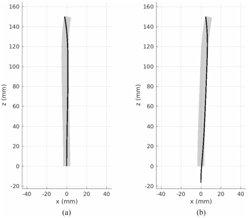
Inner (black) and outer (gray) tubes in the presence of 3 mm clearance with (a) no straight transmission length and (b) a 17-mm straight transmission length of the inner tube. The tube centerlines in (b) are not symmetric due to the transmission length.
To show how tip position varies with transmission length and clearance, tip position difference with respect to the zero clearance/zero transmission length model is plotted in Fig. 9 for varying transmission length and a discrete set of clearances. The plotting range for transmission length in the figure is limited to elastically stable lengths based on [13] and [25].
Fig. 9.
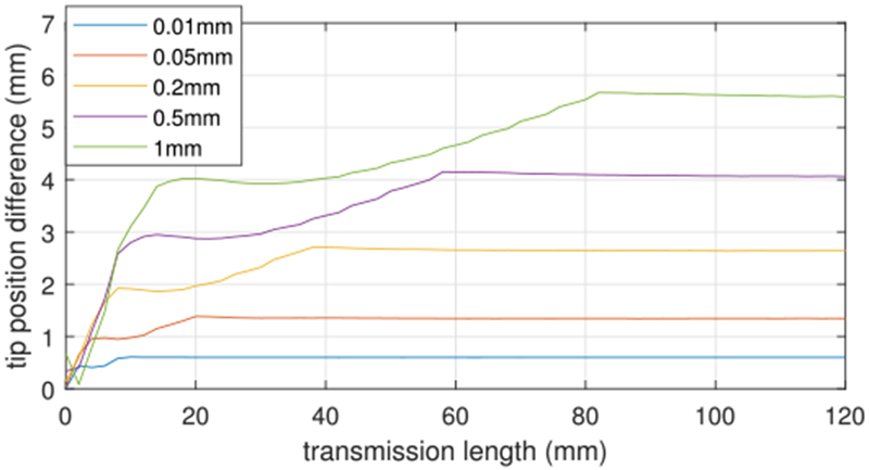
Difference in tip position compared to zero-clearance model as a function of transmission length for five values of clearance.
In Fig. 5, it was observed that for small rotation angles, the tip position difference first increases, then decreases, and then increases again. This can be explained as follows. Initially, the tips of both tubes diverge from the tip position predicted by zero-clearance model and are relatively symmetric with respect to the tip position predicted by the zero-clearance model. When the interaction between the tubes becomes significant, the outer starts pulling the inner tube toward itself and the tip of inner tube passes by through tip position predicted by the zero-clearance model. Then, as the base rotation goes to 180°, the tip position differences of both tubes increase as the overall shapes approach to the shapes of Fig. 8(b).
C. Effect of Clearance and Friction on Contact Force Distribution
When the base of a tube pair is rotated away from 0°, the standard zero-clearance model predicts a concentrated moment applied between the tubes at their tips. With the inclusion of tube clearance, this concentrated moment is produced by a point force at the tip acting in combination with an oppositely directed force distribution located close to, but not at, the tip. To see the effect of clearance on the magnitudes and the distances between the two forces comprising this moment, the forces in the frictionless case are plotted as a function of arc length for θ2,b = 180° in Fig. 10. Note that, due to discretization, distributed forces are modeled as concentrated forces applied at the discretization points. As the clearance decreases, the forces increase in magnitude and approach each other so as to produce approximately the same net moment around 0.338 Nm. This is the moment required to straighten each of the tubes, which can be computed as bending stiffness × curvature.
Fig. 10.
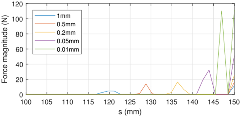
Contact force magnitude versus arc length near tube tips for five values of clearance.
The distribution of the contact forces and their magnitudes vary with the base rotation. As base rotation angle increases from zero to 180°, the contact forces increase in magnitude and move toward the ends of the tubes. This is shown in Fig. 11, where the contact forces are depicted as green circles with diameters indicating magnitude of force. The green circle at the tip grows as the base rotates. These force magnitudes are plotted versus arc length in Fig. 12 for a superset of base rotation angles. Note that a third contact region near the base is also shown. The clearance is 0.05 mm in both figures.
Fig. 11.
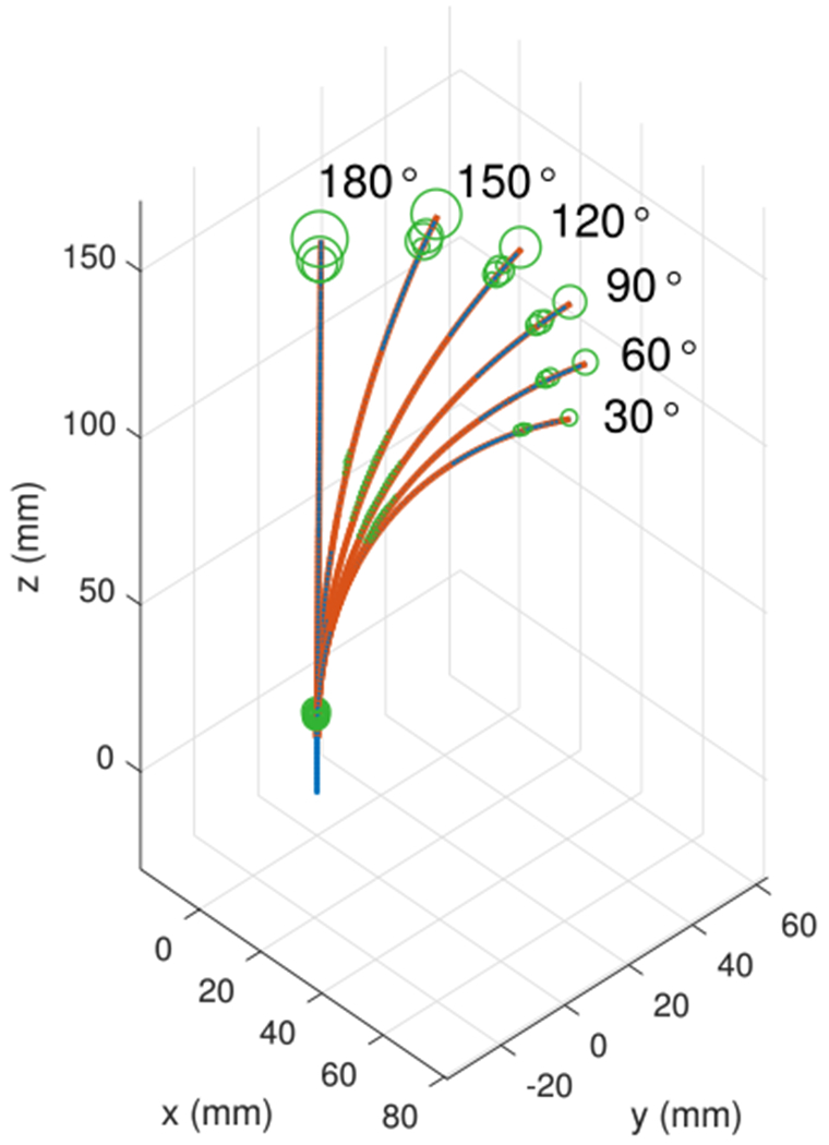
Force distribution and magnitude as a function of base rotation angle for a clearance of 0.05 mm. Contact forces are visualized as green circles with diameters proportional to force magnitude.
Fig. 12.
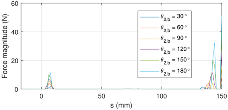
Contact force magnitude as a function of arc length for six values of base rotation angle and a clearance of 0.05 mm.
The effect of friction on the contact force distributions is shown in Fig. 13 for a base rotation angle of 180°. Here, the contact forces magnitudes include both the normal and friction components. Even so, the force magnitudes are slightly reduced. This is due to the fact that friction reduces tube rotation leading to less tube straightening near the tips. Since the tip forces are required to straighten the tubes, they are also reduced.
Fig. 13.
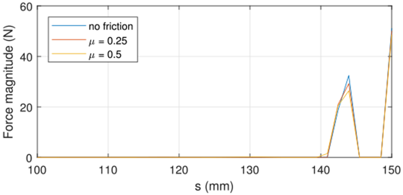
Contact force magnitude versus arc length near tube tips for three values of friction coefficient and a tube clearance of 0.05 mm.
D. Effect of Clearance and Friction on Tip Position of Three-Tube Robot
Consider the three-tube robot illustrated in Fig. 3(b) with parameters given in Table II. Assuming the base of the outermost tube is fixed and that the outer tube pair is constrained to rotate, but not translate with respect to each other (creating a section of varying curvature, but fixed length), the configuration space of the three-tube robot consists of the two rotations of tube 2 and tube 3 and one translation of tube 3. A set of configurations was sampled from a 4 × 4 × 4 uniform grid in the configuration space. The tip displacements induced by clearances (0.0425 mm between tubes 1 and 2; 0.0625 mm between tubes 2 and 4) and friction (friction coefficient of 0.2) were computed for these configurations. The mean and maximum differences in tip position and tangent angle for models with clearance and with clearance and friction are compared with the zero-clearance/frictionless model in Table III. one can see that the errors associated with friction are substantially larger than those associated with clearance alone. Fig. 14 depicts the configurations of maximum position difference. Note that there are four solutions of the friction model for each configuration depending on the directions of the relative tube rotations to reach the configuration. The tip positions differ significantly based on the relative rotation direction of tubes 2 and 3, but the difference is small with respect to the relative rotation direction of tubes 1 and 2.
TABLE III.
Differences in Tip Position Between Standard and Nonzero-Clearance Models
| Model | Mean pos. diff. (mm) | Max. pos. diff. (mm) | Mean tan. diff. (°) | Max. tan. diff. (°) |
|---|---|---|---|---|
| Clearance | 1.8(±1.0) | 4.2 | 2.7(±1.2) | 5.1 |
| Friction | 6.1(±5.7) | 23.8 | 10.7(±9.8) | 45.6 |
Fig. 14.
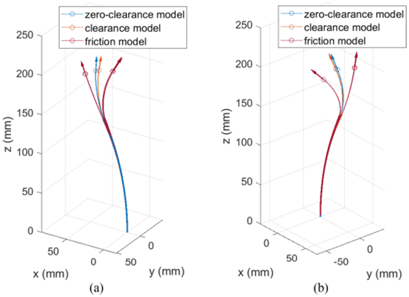
Comparison between zero- and nonzero-clearance models with and without friction at configurations of maximum tip position difference between zero- and nonzero-clearance models (a) without friction and (b) with friction. The circles and the arrows indicate the tip positions and tangent vectors, respectively.
V. Physical Experiments
To validate the model, three experiments are reported here. The first experiment is designed to evaluate the clearance model and uses a tube pair with an optically clear outer tube to enable direct visualization of the the contact regions. The second experiment investigates the effect of path history on robot configuration for a tube pair. These experiments demonstrate how large pure rotations, which are assumed by the friction model presented in Section III, produce bounding configurations. This is done by comparing solutions for path histories combining rotations and translations. The third experiment evaluates modeling error of the proposed clearance and friction models for path histories consisting of large pure rotations. A three-tube robot of a size and design suitable for surgery is used in these experiments. Details of each experiment are provided in the subsections below.
A. Validation of Frictionless Clearance Model
To enable visualization of contact regions, a clear tube made of fluorinated ethylene propylene (FEP) and NiTi wire were shape set [see Fig. 15(a)] and their precurvatures and normalized (dimensionless) stiffnesses as reported in Table IV were estimated based on images of the individual tubes and the combined tubes, respectively. Only normalized tube stiffnesses are listed since the clearance model depends only on the relative stiffness of the tubes. The values of Poisson’s ratio used were selected as the nominal material values. To measure the contacts with respect to arc length, the clear tube was scribed circumferentially every 3.175 mm (1/8 inches) [see Fig. 15(b)]. A line was also scribed longitudinally along the length of the tube to define a coordinate frame for each cross section. The angle of the contact region with respect to the coordinate frame was measured by sliding a paper protractor (see Fig. 16) along the tube to each contact region and measuring the angle between the longitudinal line and the contact line. The contact line between the NiTi wire and clear tube appeared as a dark line segment as shown in Fig. 15(b). The consistency of these measurements is empirically estimated to be ±1.5 mm in arc length and ±5° in circumferential angle.
Fig. 15.
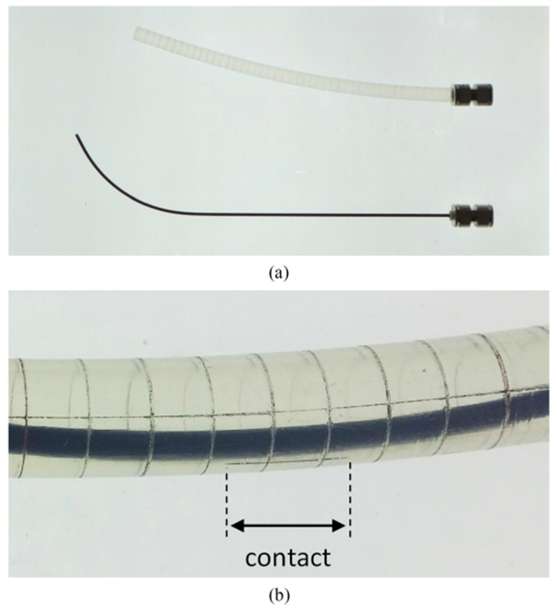
Two-tube robot comprised of a clear plastic (FEP) tube and NiTi wire. (a) Robot disassembled. (b) Closeup view showing contact as dark line segment. Circumferential and longitudinal scribe marks are also shown.
TABLE IV.
Parameters of Tube Pair
| Tube 1 | Tube 2 | ||
|---|---|---|---|
| Section 1 | Section 1 | Section 2 | |
| Length (mm) | 145 | 17 | 165 |
| Curvature (mm−1) | 1/365 | 0.0 | 1/56 |
| Bending Stiffness | 1 | 0.81 | |
| Poisson’s ratio | 0.48 | 0.3 | |
| Clearance (mm) | 1.625 | ||
Fig. 16.
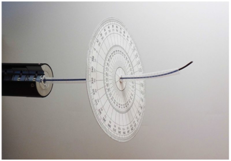
Two-tube robot shown in drive system with protractor for measuring contact angles.
To evaluate the clearance model by itself without considering friction or other history-dependent phenomena, an oscillatory path of decreasing amplitude was used to approach each rotational configuration [26]. The path consists of a sequence of 20 angular offsets from the desired angular configuration: {+40°, −38°, +36°, …, −2°, 0°}. The effect of this sequence of decreasing-amplitude oscillations is to release torsional twisting due to path history.
The contact regions for seven relative angles were measured and are reported in Fig. 17. Fig. 17(a) shows the minimum distance between the wire and tube. The maximum possible distance is the clearance which is shown as a dashed line and corresponds to the intersection of the two centerlines. The three regions of contact between the wire and tube occur over the intervals for which the distance is zero. Note that the distal contact region consists of a point at the tip of the tube.
Fig. 17.
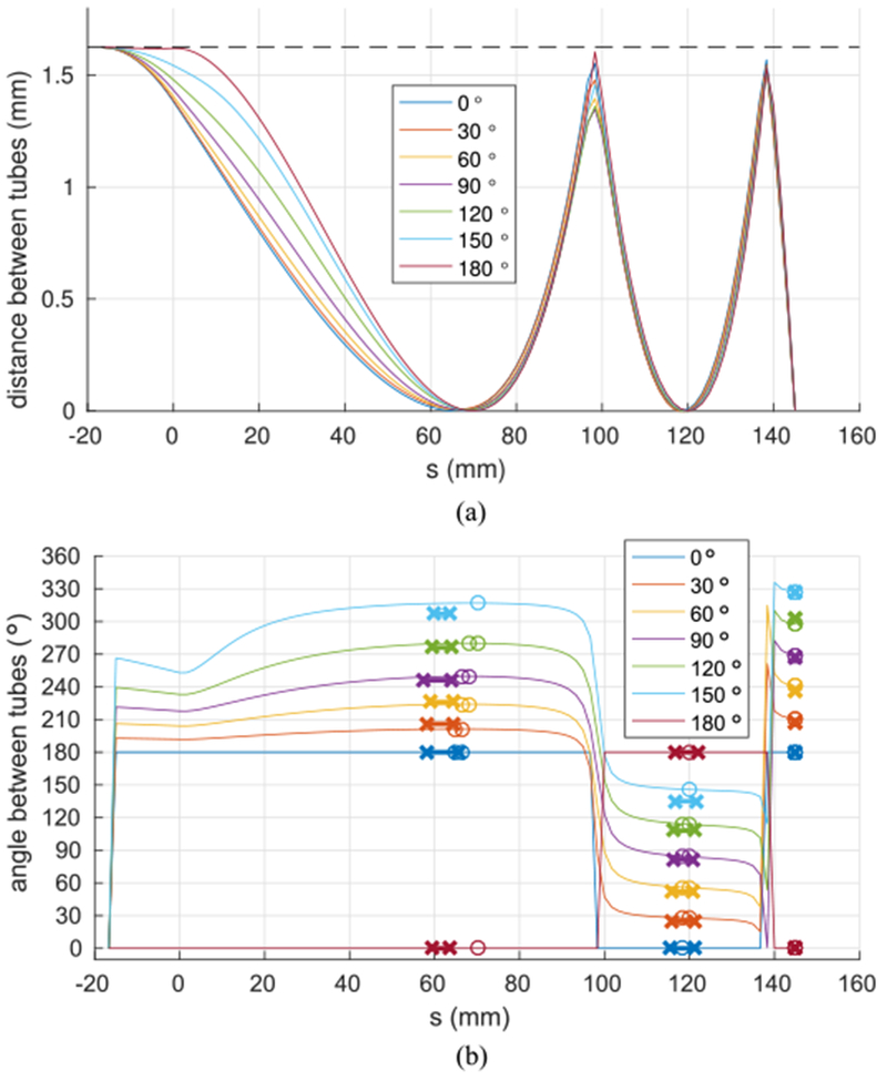
Minimum directed distance between clear tube and wire. (a) Minimum radial distance. (b) Angle with respect to clear tube cross section at which minimum distance occurs. Model-predicted contacts are shown with circles. Experimentally measured contacts are shown with Xs.
The angle of the direction of minimum distance between the tube and wire measured with respect to the tube cross section is plotted in Fig. 17(b). The predicted contact regions (zero distance) are marked by circles while the measured contact regions are denoted by line segments marked with Xs. There is good agreement between predicted and measured contact regions. For the proximal contact, the differences in contact centroid position and cross-section angle are given by 6.4 ± 1.7 mm and 3.5 ± 3.4°, respectively. For the middle contact, the differences in contact centroid position and cross-section angle are given by 0.6 ± 0.3 mm and 3.7 ± 3.8°, respectively. Since the third contact region is a point of contact at the tube tip, there is no difference in contact location and the difference in contact angle is given by 2.3 ± 2.3°.
Recall that the zero-clearance model requires a concentrated moment to be applied to the tip of the outer tube to produce equilibrium on this cross section. This experiment reveals that the moment is actually generated by the distal pair of forces acting over a moment arm of about 26 mm.
B. Effect of Path History on Kinematic Configuration
The friction model presented in Section III assumes sufficient prior motion between contacting tube pairs so that the maximum Coulomb friction force is acting at each point of contact. It also assumes that this friction force is entirely directed so as to produce a twisting intertube torque. This implies that the prior motion was a pure rotation. To investigate the effect of prior rotation and translation on a tube pair, experiments were performed using the tubes shown schematically in Fig. 18 with parameters given in Table V.
Fig. 18.

Schematic of tube pair used in path history experiment.
TABLE V.
Parameters of Tube Pair Used in Path History Experiment
| Tube 1 | Tube 2 | |||
|---|---|---|---|---|
| Section 1 | Section 2 | Section 1 | Section 2 | |
| Length (mm) | 17 | 150 | 184 | 86.4 |
| y-curvature (mm−1) | 0.0 | 1/288.1 (1/265) | 0.0 | 1/79.3 (1/55) |
| x-curvature (mm−1) | 0.0 | −1/24968.4 (0.0) | 0.0 | −1/2590.7 (0.0) |
| Bending Stiffness | 1 | 0.221 (0.286) | ||
| Poisson’s ratio | 0.3014 (0.3) | −0.2307 (0.3) | ||
| OD \ ID (mm) | 2.305\1.95 | 1.875\1.6 | ||
The goal of the experiments was to verify that configurations reached by sufficiently large pure rotations would maximize or minimize the relative twist between the tubes compared to paths comprised of combined rotations and translations. Furthermore, one can anticipate that sufficiently large pure translations could act to reduce frictional torsional twisting so that they approach the solution predicted by the frictionless model.
Thirty-seven configurations were considered consisting of relative rotations at 10° intervals from 0° to 360° and a relative translation of 43 mm such that the curved portion of the inner tube was extended halfway from the outer tube. For each configuration, eight path histories were generated and the tip twist angle and position coordinates were recorded using electromagnetic sensors. Path histories were comprised of pure rotations (two directions), pure translations (two directions), and combined translation and rotation (four directions). Path histories were constructed by first moving to an offset configuration (90° for rotations, 10 mm for translations) and then moving to the target configuration. Rotation and translation were done simultaneously at uniform rates to linearly interpolate the offset and target configurations.
We also estimated the frictionless solution with the standard kinematics model [10] calibrated using a least squares minimization over the model parameters to minimize the sum of tip position errors, expressed as
| (48) |
where ϕ and qi are the set of calibration parameters and the configuration of the ith measurement, respectively, and pi,m, pt(ϕ, qi) are the measured and theoretical tip positions. The model parameters were calibrated using data from all eight paths and the resulting values are also given in Table V. The bold numbers in the table are the calibrated parameters and the numbers in the parentheses are the initial values used in the calibration.
Note that the Poisson’s ratio is negative for the inner tube. Recalling that the ratio of bending to torsional stiffness is given by 1 + ν, a negative value indicates that the stiffness ratio is smaller than anticipated. While beyond the scope of this paper, this is likely due to the higher strain in this tube leading to nonlinear behavior. In particular, the maximum strains due to bending are 0.34% for the outer tube and 1.23% for the inner tube. Only the inner tube enters the nonlinear strain region (strain > 1%) and it is the only tube that experiences a negative Poisson’s ratio.
Fig. 19 depicts the relative angle at the tips of the tubes as a function of base rotation angle. As anticipated the maximum and minimum twist angles for all base rotations correspond to approaching the configuration using a pure rotation. Also as expected, the two solutions corresponding to pure translations yield practically identical values of tip angle which are very close to the estimated zero-friction solution. Furthermore, the pairs of solutions combining two directions of translation with a specific direction of rotation are very close to each other and lie between the corresponding pure rotation solution and pure translation solutions.
Fig. 19.
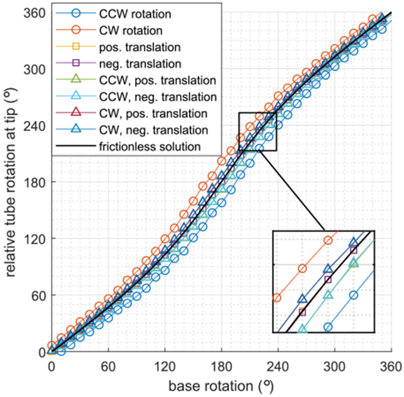
Relative tube rotation angle at the tip versus base rotation angle. Measurements for eight path histories are shown for each base angle.
As the tube pair is rotated through a complete revolution, the tip of the inner tube traces out an elliptical path as shown in Fig. 20. The tip paths all lie approximately on a plane rotated 23° from xy-plane about the y-axis. The maximum offset from this plane is less than 0.5 mm. The pure rotation solutions are shown as solid curves and the eight path-based configurations are depicted for a set of six base angles. The estimated frictionless solution is also shown.
Fig. 20.
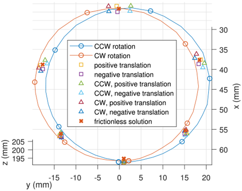
Tip positions of Fig. 19. Pure-rotation path-history measurements are plotted as solid curves. The eight individual path history solutions are plotted at 60° intervals for clarity.
It can be observed that for each solution set, the pure rotations are farthest apart. The pure translations are located centrally, close to each other and close to the estimated frictionless solution. As in Fig. 19, the pairs of combined rotations and translations lie between the pure rotations and pure translations.
The 3-D distances between the experimental measurements and the estimated frictionless solution are plotted as a function of base rotation angle in Fig. 21. The distances are largest near a relative rotation of 180° since this is where the contact and friction forces are largest due to the precurvatures of the tubes opposing each other. This plot illustrates how pure rotation path histories produce the largest tip errors for tube pairs. The friction model proposed in this paper is intended to compute these maximum-error configurations.
Fig. 21.
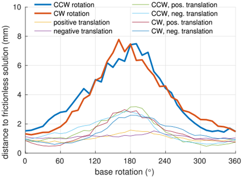
Average distance of tip position from predicted frictionless solution based on path history.
C. Validation of Friction Model
These experiments evaluate the prediction error of the friction model for path histories comprised of pure rotations. Its performance is compared to the standard frictionless model [10] as well as to the frictionless clearance model. The three-tube robot shown in Fig. 22 was used and a 6-DOF electromagnetic (EM) sensor (Model 180, Ascension Technologies) recorded tip position and orientation. Sensor position and orientation accuracies are 1.4 mm rms and 0.5° rms. We performed our experiments in the region with the best measurement quality indicated by the manufacturer’s software and averaged measurements over 2 s (about 200 measurements) to clear our high-frequency noise. Ignoring rigid-body motions, the robot degrees of freedom consist of the two relative rotations of the three tubes and the relative translation of the distal tube with respect to the proximal pair (the proximal pair of tubes are designed to translate together). The nominal tube parameters are given in Table II.
Fig. 22.
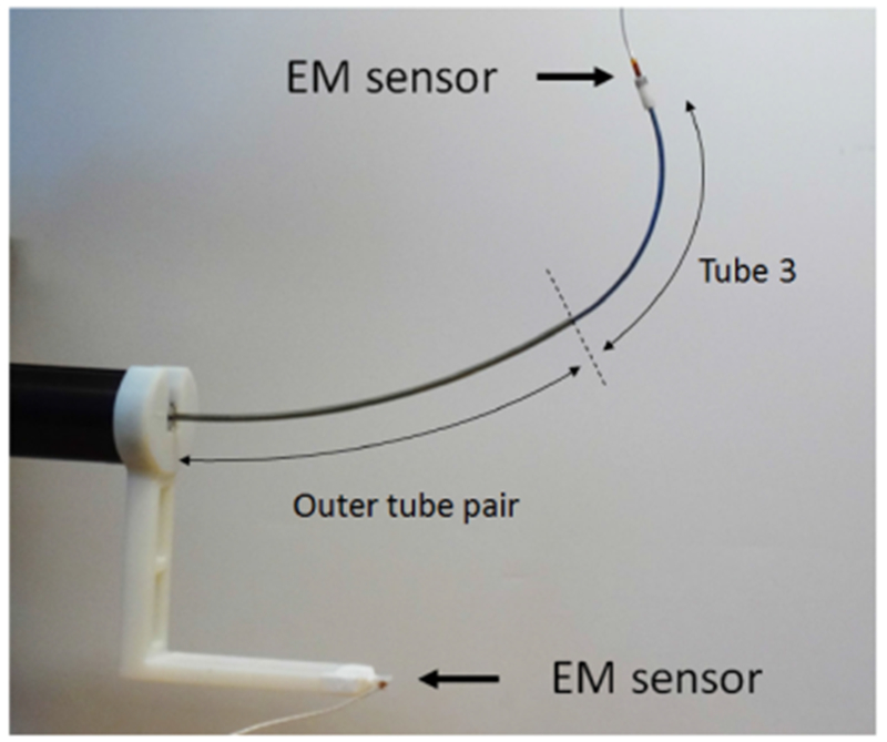
Three-tube robot. EM sensors are used to measure the relative transformation from the robot base to the robot tip.
Since each robot configuration is described by two relative angles, a specific configuration can be approached from four angular “directions.” The four angular directions correspond to the following rotation directions of the second and third tubes relative to the first and second tubes, respectively: (1) CCW, CCW, (2) CCW, CW, (3) CW, CCW, and (4) CW, CW. Each of the relative rotations is performed by 90° of tube base rotation, which was found to be sufficient to produce the maximum torsional friction effect. An example configuration is depicted in Fig. 23, in which path direction produced four different tip positions that differ from each other by up to 17 mm.
Fig. 23.
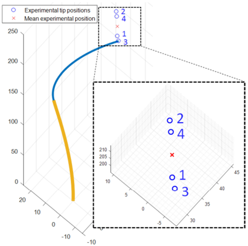
Example showing four experimentally measured robot tip positions corresponding to the four rotational paths of a single set of base angles.
Tip position and tangent direction were collected for each of the four approach directions at 8 × 8 × 8 configurations evenly distributed in joint space. This dataset was divided into two subsets. The first, comprising 62 configurations (×4 angular directions), was used for calibration while the remaining 450 configurations (×4 angular directions) were used for error computation. The 62 configurations were selected as 4 × 4 × 4 subset configurations evenly distributed in the joint space. Two configurations in the set of 4 × 4 × 4 were excluded since they were predicted to possess multiple solutions using the standard zero-clearance model with the nominal parameters.
Model calibration was performed as a least squares minimization over the model parameters. For these experiments, we minimized the weighted sum of tip position and tangent errors, expressed as
| (49) |
where ϕ and qi are the set of calibration parameters and the configuration of ith measurement, respectively, and pi,m, pt(ϕ, qi), ti,m and tt (ϕ, qi) are the measured and the theoretical tip positions and the measured and theoretical tip tangents, respectively. This choice of weighting function scales 1° of tangent error to be equal to 1mm of position error.
The calibrated tube parameters for the standard frictionless model are given in Table VI and those of the frictionless clearance model and the friction model are given in Table VII. Only the normalized tube stiffnesses are listed since the model depends only on the relative stiffness of the tubes. In the clearance model and the friction model, the tube-to-tube clearances are not calibrated but given by the nominal inner and outer diameters of the tubes. The bolded numbers in the tables are the parameters that have been calibrated while the others werefixed in the calibration. Parameters were calibrated through a gradient descent method. The friction coefficients were calibrated during a second pass using a 2-D grid search to avoid local minima. This approach allows the frictionless clearance model and the friction model to share the same tube parameters. Furthermore, calibration performed over all parameters simultaneously was performed and did not improve the model fit.
TABLE VI.
Standard Frictionless Model Parameters
| Tube 1 | Tube 2 | Tube 3 | |||
|---|---|---|---|---|---|
| Section 1 | Section 1 | Section 2 | Section 1 | Section 2 | |
| Length (mm) | 150 | 17 | 150 | 184 | 86.4 |
| y-curvature (mm−1) | 1/276.5 | 0.0 | 1/212.4 | 0.0 | 1/61.01 |
| x-curvature (m−1) | −1/1775.0 | 0.0 | −1/9.791 | 0.0 | −1/3.526 |
| Bending Stiffness | 1 | 1.006 | 0.2742 | ||
| Poisson’s ratio | 0.3208 | 0.3415 | −0.1750 | ||
Estimated parameters are bolded.
TABLE VII.
Parameters of Frictionless Clearance and Friction Models
| Tube 1 | Tube 2 | Tube 3 | |||
|---|---|---|---|---|---|
| Section 1 | Section 1 | Section 2 | Section 1 | Section 2 | |
| Length (mm) | 150 | 17 | 150 | 184 | 86.4 |
| y-curvature (mm−1) | 1/282.8 | 0.0 | 1/212.6 | 0.0 | 1/62.37 |
| x-curvature (m−1) | −1/291.3 | 0.0 | −1/9.879 | 0.0 | −1/3.313 |
| Bending Stiffness | 1 | 0.9929 | 0.1990 | ||
| Poisson’s ratio | 0.3000 | 0.3256 | −0.1543 | ||
| Outer diameter | 2.64 | 2.31 | 1.83 | ||
| Clearance (mm) | 0.0425 | 0.0625 | |||
| Friction coefficient | 0.22 | 0.12 | |||
Estimated parameters are bolded.
Note that while the tube precurvatures were in the y-direction, the calibration allowed nonzero curvatures in the x-direction. In other words, the y-curvature is the main tube precurvature and the x-curvature is off-plane curvature that can be produced unintentionally during the manufacturing process. The x-curvature is at least 46 times smaller than the y-curvature in Tables VI and VII.
Also, notice that the calibrated values for Poisson’s ratio of the innermost tube for all models are negative. As described in the tube pair example above, this is likely due to the higher strains in this tube leading to nonlinear behavior. In particular, the maximums strains due to tube bending are computed to be 0.73%, 0.65%, and 1.68% for tubes 1 to 3, respectively, using the tube parameters in Table VII. Only tube 3 enters the nonlinear strain region (strain > 1%) and it is the only tube that experiences a negative Poisson’s ratio.
The mean and maximum errors in tip position and tangent direction for the three models were computed using the 450 robot configurations (×4 angular directions) collected as described earlier. The results are reported in Table III along with the CPU evaluation time for each model. All models were coded in MATLAB and running on a PC equipped with Intel(R) Core(TM) i5–3470 CPU. Since the frictionless standard and clearance models produce a single solution for each robot configuration, the inclusion of all four angular-directions measurements in both the calibration and evaluation steps is similar to employing the “average” tip position and tangent direction for each configuration [26].
TABLE VIII.
Modeling Error of Calibrated Standard, Clearance, and Friction Models
| Model | Mean pos. error (mm) | Max. pos. error (mm) | Mean tan. error (°) | Max. tan. error (°) | Evaluation time (sec) |
|---|---|---|---|---|---|
| Standard | 4.1(± 2.3) | 11.5 | 4.9(± 2.7) | 14.3 | 0.23(± 0.10) |
| Clearance | 3.7(± 2.1) | 11.6 | 4.9(± 2.7) | 14.9 | 5.3(± 2.2) |
| Friction | 2.2(± 0.9) | 5.9 | 1.8(± 0.9) | 7.1 | 11.7(± 4.4) |
There is no statistically significant difference between the mean prediction errors of the frictionless standard and clearance models and the maximum errors are also similar. Note that the two models have the same number of parameters. While not included here, we also fit the clearance model while allowing the clearance parameters to vary. These additional parameters had little effect on the average and maximum errors.
In contrast, the friction model provides a significant improvement over the other two models. The error mean and standard deviation are reduced in both tip position and tangent direction. Perhaps the most important reduction is that the maximum errors in position and tangent direction are reduced by 48% and 50%, respectively. Note, however, that, as implemented, the friction model takes 51 times as long to evaluate.
A comparison of models at a typical configuration is shown in Fig. 24. The friction model produces four solutions according to the angular directions by which the configuration is approached. These solutions can be seen to approximate the four corresponding experimental measurements. The frictionless models each produce a single solution that, to some extent, models the “mean” of the four solutions.
Fig. 24.
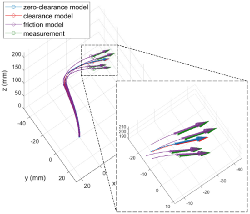
Example configuration comparing four experimental solutions with the single predictions of the standard and clearance models and the four solutions of the friction model. Circles denote tip positions and semitransparent arrows indicate tip tangent vectors.
VI. Conclusion
This paper has demonstrated how tube clearance and torsional Coulomb friction can be incorporated in the existing mechanics-based but approximate kinematic model. The clearance model by itself does not reduce modeling error, but is a necessary step for computing friction torques based on the contact forces between tubes. It also reveals some interesting details about tube interaction. For example, the concentrated moment that the standard model assumes at the end of each tube (except the most distal one) was found to be comprising a distributed force and point force acting as a force couple over a centimeter-scale distance.
The friction model, as formulated, assumes that the maximum Coulomb force is generated along the entire interface between each contacting pair of tubes and is directed circumferentially. This produces solutions in which friction either maximizes or minimizes the twisting between each pair of contacting tubes and corresponds to purely rotational path histories. It was demonstrated experimentally for a tube pair that purely rotational path histories produce the maximum tip error compared to translations or mixed translations and rotations. Consequently, the friction model provides worst case estimates of actual tip configurations for arbitrary path histories.
Additional experiments revealed that, for path histories of pure rotation, the friction model produced a significant reduction in average error. Maximum error was also reduced by half when compared to the standard kinematic model. The price paid for improved modeling accuracy was a substantial increase in model computation time.
While such a model is not appropriate for real-time feedback control, it is valuable for path planning since it can be used to estimate the maximum path-dependent errors for a specific robot configuration. Furthermore, knowledge of how path history (rotations versus translations) affects friction-induced tube twisting can also guide path planning. For example, set-point interpolation can be designed to favor performing translations after rotations in order to reduce torsional friction.
Acknowledgments
This work was supported by the National Institutes of Health under Grant R01HL124020.
Nomenclature
- n
Number of tubes
- i
Tube index, numbered from outer to inner
- j
Arc-length discretization index, numbered from base to tip
- k
Index renumbered from combined index ij
- s
Arc-length parameter
- pi(s)
Three-dimensional (3-D) centerline curve of tube i
- Ri(s)
3 × 3 rotation matrix of body frame of tube i
- êz
Unit z-axis vector, i.e., [0 0 1]T
- ui(s)
3-D curvature vector of tube i
- ûi(s)
3-D pre-curvature vector of tube i
- θi,b, θb
Base rotation of tube i and base rotation vector
- li,b, lb
Translation of tube i and translation vector
- ki,xy, ki,z
Bending and torsional stiffnesses of tube i
- Ki
3 × 3 stiffness matrix of tube i
- Rz(α)
3 × 3 rotation matrix of rotation of α about z-axis
- gi(s)
Elastic potential energy per length of tube i
Vector comprised of discretized ui (s)
Vector comprised of discretized ûi (s)
Vector comprised of discretized pi (s)
Vector comprised of of all tubes
Vector comprised of of all tubes
Vector comprised of of all tubes
- Ni
Number of discretized points on tube i
- N
Sum of Ni of all tubes
Function that returns tube centerlines given tube curvatures
Tube-contact constraint function
- E
Potential energy of all tubes
- K
Matrix comprised of stiffnesses corresponding to
- ν
Poisson’s ratio
Nominal value of for linearization of and
Value of corresponding to
Difference between and , i.e.,
Difference between and , i.e.,
- Pij
3 × 3 projection matrix of cross section of tube i at j-th discretized point
- Jp
Jacobian matrix of
- Jω
Jacobian matrix of Ri(s) w.r.t.
- Sij
Selection matrix to pick pi (sij) and −pi+1(sij) from
- ci
Clearance between tube i and tube i + 1
- ri,in, ri,out
Inner and outer radii of tube i
- g, Xk , xk, qk
Initialization variables of inner loops of clearance model and friction model
- Yk
Initialization variable of inner loop of friction model
- λ
Lagrange multiplier vector associated with tube contact constraint
- Q(λ), h(λ)
Variables computed in each iteration of inner loops of clearance model and friction model
- fnormal, k
Normal contact force on outer tube applied by inner tube at sk(= skij)
- fnormal
Vector comprised of fnormal, k for all k
- ffriction, k
Friction force on outer tube applied by inner tube at sk(= skij)
- τi,k
Torque on tube i induced by tube-to-tube friction at sk(= skij)
- τ
Vector comprised of τi,k for all k
- μk
Friction coefficient between tubes associated with k-th contact constraint
- ηk
Direction of prior rotation of inner tube w.r.t. outer tube at k-th contact constraint. Either 1 (CCW) or −1 (CW)
Biographies
Junhyoung Ha received the B.S. and Ph.D. degrees in mechanical engineering from Seoul National University, Seoul, South Korea, in 2008 and 2015, respectively.
He is currently a Postdoctoral Fellow with Boston Children’s Hospital, Harvard Medical School, Boston, MA, USA. His research interests include medical robotics, continuum robots, control, and optimization.

Georgios Fagogenis received the diploma in mechanical engineering from the National Technical University of Athens, Athens, Greece, in 2007, the M.S. degree in mechanical engineering from ETH Zurich, Zurich, Switzerland, in 2009, and the Ph.D. degree in electrical engineering from Heriot-Watt University, Edinburgh, Scotland, in 2016.
He is currently a Postdoctoral Fellow with Boston Children’s Hospital, Harvard Medical School, Boston, MA, USA. His research interests include medical robotics and autonomous surgery.

Pierre E. Dupont (M’99–SM’03–F’11) received the B.S., M.S., and Ph.D. degrees in mechanical engineering from Rensselaer Polytechnic Institute, Troy, NY, USA, in 1982, 1984, and 1988, respectively.
From 1988 to 1990, he was a Postdoctoral Fellow with the School of Engineering and Applied Sciences, Harvard University, Cambridge, MA, USA. He was a Professor of mechanical engineering and biomedical engineering with Boston University, Boston, MA, USA. He is currently the Chief of Pediatric Cardiac Bioengineering and Professor ofSurgery with Boston Children’s Hospital, Harvard Medical School, Boston, MA, USA where his group develops instrumentation and imaging technology for minimally invasive surgery.
Appendix A. Efficient Computation of
An efficient way of computing is presented here. Consider Q given in (28) for the frictionless case and in (45) for the case with friction. The derivation here focuses on (45) since (28) is a special case of (45) with zero friction coefficients, i.e., μk = 0. The matrix Q in (45) can be expressed without Σ as
| (50) |
with
| (51) |
| (52) |
| (53) |
where k1, k2, …, km are the indices of nonzero λk. Applying the Woodbury matrix identity [27], Q−1 h is given by
| (54) |
Here, the diagonal matrices K and Λ can be efficiently inverted by component-wise inversions. The other matrix to invert, Λ−1 + XK−1 YT, is a 3 m × 3 m matrix where m is the number of nonzero λk. The dimension of this matrix is smaller than that of . Thus, the computation involved in the matrix inversion is more efficient, especially when λ is nearly converged since λk in the converged solution are mostly zero, i.e., the contact forces are mostly zero along the length, as shown in Figs. 10, 12, and 17.
For more efficient computation, (Λ−1 + XK−1 YT )−1 XK−1 h can be set equal to v and computed through solving the linear equation below for the unknown v:
| (55) |
Then is computed by substituting v in
| (56) |
In summary, the equation can be efficiently solved for by first solving (55) for v and substituting the resulting v into (56).
Appendix B. Analytic Forms of Jp and Jω
The Jacobian matrix is the linear map between changes in tube curvatures and changes in tube centerlines around the initial solution . Similarly, maps the changes in tube curvatures to the angular displacements of the tube frames {Ri(s)}i=1,…,n. The analytic forms of theses matrices are derived here. The formulation of Jp is more accurate than (26) in [16] as it accurately incorporates tube curvature between discretized points.
As the tube lengths are discretized, the Jacobian matrices depend on the numerical integration of the centerlines and the frames along the tubes. While any numerical integration can be chosen, the analytic forms of Jp and Jω to be derived here are based on Euler integration in the exponential coordinate of SE(3), shown as follows:
| (57) |
where Δs is the arc length step, êz = [0 0 1]T is the unit vector along the z-axis, and Ti(s) ∈ SE(3) is the 4 × 4 transformation matrix that represents the body frame and the position of tube i at s, which is of the form
| (58) |
Defining and as the Jacobian matrices for tube i only, they align diagonally in Jp and Jω of the form
| (59) |
By decomposing Jp,i and Jω,i further into 3 × 3 blocks, their (j, k)th 3 × 3 blocks can be expressed, respectively, as
| (60) |
| (61) |
which represent the linear maps between small changes in the curvature at kth point on tube i and corresponding changes in pi(s) and ωi(s) at jth point on tube i. Here is the angular displacement of Ri(s) from , i.e., .
To derive Jp,i(j, k) and Jω,i(j, k), we will express the relations of pi(sij), ωi(sij), and ui(sik) as a matrix equation and expand this as the first-order Taylor series. This results in a set of linear equations that represent linear maps between small changes of (pi(sij), ωi(sij), ωi(sik)), where the linear maps correspond to the matrices Jp,i(j, k) and Jω,i(j, k). Note that Jp,i(j, k) and Jω,i(j, k) for j < k are zero matrices as the curvature change at a point doesn’t influence pi or ωi at more proximal points. The following derivations will thus focus on j ≥ k.
Let us begin with the following obvious equation:
| (62) |
To have ui(sjk) appear in the equation, will be substituted with an exponential map associated with ui(sjk), as follows:
| (63) |
where
| (64) |
Note that (63) relates pi(sij), ωi(sij), and ui(sik) as Ti(sij) is a function of pi(sij) and ωi(sij), i.e.,
| (65) |
The first-order Taylor expansion of (63) with respect to (pi(sij), ωi(sij), ui(sik)) about the initial solution (, , ) is given by
| (66) |
where V* is defined by substituting ui(sik) in (64) with . Here dexp(⋅) denotes the differential of the exponential map [28] and the variables with δ represent the small changes of the corresponding variables. After an algebraic manipulation, (66) reduces to the following linear equations:
| (67) |
| (68) |
where the matrices Jp,i(j, k) and Jω,i(j, k) can be expressed using the differential of the exponential map. Based on the formulations of the differential of the exponential map in [28], Jp,i(j, k) and Jω,i(j, k) are given by
| (69) |
| (70) |
with and defined as
| (71) |
| (72) |
where the 3 × 3 matrices dexp(⋅) and C(⋅) are given in [28] by
| (73) |
| (74) |
and α and β are given by
| (75) |
In summary, the overall computation is as follows:
-
1)
For tube i, compute Jp,i(j, k) and Jω,i(j, k) over j = 1, …, Ni and k = 1, …, Ni using (69)–(75). Remember that Jp,i(j, k) = Jω,i(j, k) = 03×3 for j < k.
-
2)
Build Jp,i and Jω,i by collecting Jp,i(j, k) and Jω,i(j, k) as (j, k)th 3 × 3 blocks.
-
3)
Repeat (1) and (2) for all tubes and build Jp and Jω using (59).
Footnotes
Color versions of one or more of the figures in this paper are available online at http://ieeexplore.ieee.org.
References
- [1].Vasilyev NV, Dupont PE, and Del Nido PJ, “Robotics and imaging in congenital heart surgery,” Future Cardiology, vol. 8, no. 2, pp. 285–296, 2012. [DOI] [PMC free article] [PubMed] [Google Scholar]
- [2].Gosline AH et al. , “Percutaneous intracardiac beating-heart surgery using metal MEMS tissue approximation tools,” Int. J. Robot. Res, vol. 31, no. 9, pp. 1081–1093, 2012. [DOI] [PMC free article] [PubMed] [Google Scholar]
- [3].Vasilyev NV et al. , “Percutaneous steerable robotic tool delivery platform and metal MEMS device for tissue manipulation and approximation: Initial experience with closure of patent foramen ovale,” Circulation: Cardiovascular Interventions, vol. 6, pp. 468–475, 2013. [DOI] [PMC free article] [PubMed] [Google Scholar]
- [4].Vasilyev NV et al. , “Tissue removal inside the beating heart using a robotically delivered metal MEMS tool,” Int. J. Robot. Res, vol. 34, no. 2, pp. 236–247, 2015. [Google Scholar]
- [5].Burgner J et al. , “A telerobotic system for transnasal surgery,” IEEE/ASME Trans. Mechatronics, vol. 19, no. 3, pp. 996–1006, Jun. 2014. [DOI] [PMC free article] [PubMed] [Google Scholar]
- [6].Anor T, Madsen JR, and Dupont P, “Algorithms for design of continuum robots using the concentric tubes approach: A neurosurgical example,” in Proc. IEEE Int. Conf. Robot. Automat., 2011, pp. 667–673. [DOI] [PMC free article] [PubMed] [Google Scholar]
- [7].Lyons LA, Webster RJ III, and Alterovitz R, “Motion planning for active cannulas,” Proc. IEEE/RSJ Int. Conf. Intell. Robots Syst., 2009, pp. 801–806. [Google Scholar]
- [8].Lyons L, III RW, and Alterovitz R, “Planning active cannula configurations through tubular anatomy,” Proc. IEEE Int. Conf. Robot. Automat., 2010, pp. 2082–2087. [Google Scholar]
- [9].Torres LG, Webster III RJ, and Alterovitz R, “Task-oriented design of concentric tube robots using mechanics-based models,” Proc. IEEE/RSJ Int. Conf. Intell. Robots Syst., 2012, pp. 4449–4455. [DOI] [PMC free article] [PubMed] [Google Scholar]
- [10].Dupont PE, Lock J, Itkowitz B, and Butler E, “Design and control of concentric tube robots,” IEEE Trans. Robot, vol. 26, no. 2, pp. 209–225, Apr. 2010. [DOI] [PMC free article] [PubMed] [Google Scholar]
- [11].Rucker DC, Jones BA, and Webster III RJ, “A geometrically exact model for externally-loaded concentric-tube continuum robots,” IEEE Trans. Robot, vol. 26, no. 5, pp. 769–780, Oct. 2010. [DOI] [PMC free article] [PubMed] [Google Scholar]
- [12].Rucker DC, Webster RJ, Chirikjian GS, and Cowan NJ, “Equilibrium conformations of concentric-tube continuum robots,” Int. J. Robot. Res, vol. 29, no. 10, pp. 1263–1280, 2010. [DOI] [PMC free article] [PubMed] [Google Scholar]
- [13].Ha J, Park FC, and Dupont PE, “Elastic stability of concentric tube robots subject to external loads,” IEEE Trans. Biomed. Eng, vol. 63, no. 6, pp. 1116–1128, Jun. 2016. [DOI] [PMC free article] [PubMed] [Google Scholar]
- [14].Lock J and Dupont PE, “Friction modeling in concentric tube robots,” in Proc. IEEE Int. Conf. Robot. Automat., 2011, pp. 1139–1146. [DOI] [PMC free article] [PubMed] [Google Scholar]
- [15].Armstrong-Helouvry B, Dupont PE, and De Wit CC, “A survey of models, analysis tools and compensation methods for the control of machines with friction,” Automatica, vol. 30, no. 7, pp. 1083–1138, 1994. [Google Scholar]
- [16].Ha J and Dupont PE, “Incorporating tube-to-tube clearances in the kinematics of concentric tube robots,” in Proc. IEEE Int. Conf. Robot. Automat., 2017, pp. 6730–6736. [Google Scholar]
- [17].Bauchau OA and Ju C, “Modeling friction phenomena in flexible multibody dynamics,” Comput. Methods Appl. Mech. Eng.,vol. 195, no. 50–51, pp. 6909–6924, 2006. [Google Scholar]
- [18].Reed KB, Okamura AM, and Cowan NJ, “Modeling and control of needles with torsional friction,” IEEE Trans. Biomed. Eng, vol. 56, no. 12, pp. 2905–2916, Dec. 2009. [DOI] [PMC free article] [PubMed] [Google Scholar]
- [19].Phee SJ, Low S, Dario P, and Menciassi A, “Tendon sheath analysis for estimation of distal end force and elongation for sensorless distal end,” Robotica, vol. 28, no. 7, pp. 1073–1082, 2010. [Google Scholar]
- [20].Agrawal V, Peine WJ, and Yao B, “Modeling of transmission characteristics across a cable-conduit system,” IEEE Trans. Robot, vol. 26, no. 5, pp. 914–924, Oct. 2010. [Google Scholar]
- [21].Kato T, Okumura I, Song S-E, Golby AJ, and Hata N, “Tendon-driven continuumrobotfor endoscopic surgery: preclinical development and validation of a tension Propagation model,” IEEE/ASME Trans. Mechatronics, vol. 20, no. 5, pp. 2252–2263, Oct. 2015. [DOI] [PMC free article] [PubMed] [Google Scholar]
- [22].Roy R, Wang L, and Simaan N, “Modeling and estimation of friction, extension, and coupling effects in multisegment continuum robots,” IEEE/ASME Trans. Mechatronics, vol. 22, no. 2, pp. 909–920, Apr. 2017. [Google Scholar]
- [23].Boyd S and Vandenberghe L, Convex Optimization . Cambridge, U.K.: Cambridge Univ. Press, 2004. [Google Scholar]
- [24].Siciliano B, Sciavicco L, Villani L, and Oriolo G, Robotics: Modelling, Planning and Control . London, U.K.: Springer-Verlag, 2010. [Google Scholar]
- [25].Ha J, Park FC, and Dupont PE, “Optimizing tube precurvature to enhance elastic stability of concentric tube robots,” IEEE Trans. Robot, vol. 33, no. 1, pp. 22–37, Feb. 2017. [DOI] [PMC free article] [PubMed] [Google Scholar]
- [26].Ha J, Fagogenis G, and Dupont PE, “Effect of path history on concentric tube robot model calibration,” in Proc. 10th Hamlyn Symp. Med. Robot., 2017, pp. 77–78. [Google Scholar]
- [27].Woodbury MA, “Inverting modified matrices,” Memorandum Rep, vol. 42, no. 106, p. 336, 1950. [Google Scholar]
- [28].Park J and Chung W-K, “Geometric integration on Euclidean group with application to articulated multibody systems,” IEEE Trans. Robot, vol. 21, no. 5, pp. 850–863, 2005. [Google Scholar]


