Abstract
In this work we present a novel, inductance-based system to measure and control the motion of bellows-driven continuum joints in soft robots. The sensing system relies on coils of wire wrapped around the minor diameters of each bellows on the joint. As the bellows extend, these coils of wire become more distant, decreasing their mutual inductance. Measuring this change in mutual inductance allows us to measure the motion of the joint. By dividing the sensing of the joint into two sections and measuring the motion of each section independently, we are able to measure the overall deformation of the joint with a piece-wise constant-curvature approximation. This technique allows us to measure lateral displacements that would be otherwise unobservable. When measuring bending, the inductance sensors measured the joint orientation with an RMS error of 1.1 °. The inductance sensors were also successfully used as feedback to control the orientation of the joint. The sensors proposed and tested in this work provided accurate motion feedback that would be difficult to achieve robustly with other sensors. This sensing system enables the creation of robust, self-sensing soft robots based on bellows-driven continuum joints.
Keywords: Inductance Sensing, Soft Robotics, Continuum Robots
1. Introduction
The emerging field of soft robotics is enabling fundamentally new ways to design, build and control robotic systems. Such soft robots exhibit complex behaviors that emerge from deliberate compliance in the actuators and structure. By incorporating passive degrees of freedom into their structure, soft robots can passively conform to the constraints of their environment and to the objects they are manipulating. Many soft robots are actuated by the flexible expansion of hermetically sealed volumes which drive compliant joints. Systems based on these principles are lightweight, flexible and have low reflected inertia. This makes them inherently safe in physical human-robot interaction. Moreover, the sealed actuators and flexible joints are well-suited to work in harsh environments where external contaminates could breach the dynamic seals of rotating or sliding shafts.
In this paper, we focus on sensing and controlling the motion of bellows-driven continuum joints. The sensing system relies on coils of insulated conductive wire wrapped around the minor diameters of the bellows. These coils form circuits with inductance values that change with the length of the bellows. The measured inductance values can be calibrated to measure the motion of the joint. We demonstrate experimentally how sensors such as these can measure and control the motion of bellows-driven continuum joints.
We utilize a joint made from four pneumatically driven bellows that are positioned around a central steel cable (Fig. 1). This joint was developed by the authors affiliated with Pneubotics. The bellows create bending torques about two axes while keeping the joint stiff in torsion. By pressurizing pairs of antagonized bellows simultaneously, the passive bending stiffness of the joint is also controllable. Joints with similar features have been developed for applications in industry and academia. These have relied on bellows [13, 2, 18,15, 14] and other soft, fluid-powered actuators [5, 21, 19].
Fig. 1.
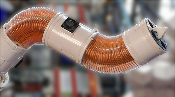
Bellows-driven continuum joints are used to create robots without finite degrees of freedom. Sensing the motion of such robots is a challenge. The inductance-based sensors presented in this work will bring estimation and control to robots like the one pictured here (created by Pneubotics).
The advantages of soft continuum joints come with the new challenge of sensing and controlling their distributed motion. While traditional robotic systems provide discrete mechanical joints on which to couple rotational or translational sensors, soft continuum joints, by their nature, do not have such convenient coupling points. Instead, the deformation of soft joints is typically measured with an external localization system, inertial measurement units (IMUs), or a set of internal sensors.
External localization systems include visual “3D motion capture,” electromagnetic tracking and radio frequency indoor positioning systems. Visual localization systems typically rely on retro-reflective markers or laser beacons [34, 25]. These systems require a line-of-sight to operate. Accordingly, they have limited utility in visually occluded workspaces. Electromagnetic tracking systems [32, 26] avoid these occlusion problems but have smaller workspaces. Radio Frequency systems may have vast workspaces but limited accuracy [33]. Moreover, high-frequency signals rapidly attenuate underwater.
In some situations, Inertial Measurement Units can be used to estimate the motion of difficult-to-sense joints in robots and humans [16, 3]. Orientation estimates from IMUs, however, are not always accurate. IMUs rely on the fusion of measurements from gyroscopes, accelerometers and a magnetometer to estimate the orientation of the sensor. The orientation is calculated by combining numerically integrated angular accelerations with drift-free measurements of the gravity vector and Earth’s magnetic field. The local magnetic field, however, can be distorted by large metal objects and electric motors [6, 4] causing errors in heading estimates. Without reliable magnetic field information, IMU heading estimates are susceptible to drift.
Naturally, orientation estimates can only measure robot motion that changes orientation. Not all joint motions change this orientation. Continuum joints can deflect laterally without changing the relative orientation of the joint ends such as when the joint is supporting a heavy load in a horizontal orientation. The two faces of the joint can be parallel to gravity but the distal end may be forced lower by the load. To estimate these deformations, intermediate orientations would need to be recorded along the length of the continuum structure.
Internal sensors measure the deformation in the system directly. The deformation can be measured by recording changes in length along well-defined paths. These length changes can be measured through the recoil of strings or tendons under tension [19, 13]. Strain can also be measured using elastomers with elements that exhibit changes in resistance or capacitance [1, 27, 29]. Elastomeric capacitive strain sensors have been integrated into fabric sleeves to measure the motion of an inflatable bellows-driven joint [35]. Optical fibers can measure strain (and thus bending) via Fiber Bragg Gratings [20] or deformation-induced attenuation [28]. Elastomeric waveguides can also be used [36, 31]. The shape of cable-like sensors can be measured through the changing distance between pairs of LEDs and phototransistors [17]. This technique was recently demonstrated on a bellows-driven continuum arm created by FESTO [14]. Inductance-based sensors have been developed by the authors Felt and Remy for use in soft actuators such as bending bellows [10], McKibben muscles [9, 11, 8] and other fiber-reinforced soft actuators [12].
Among these internal sensing technologies, inductance-based sensors provide unique advantages. String recoil systems are often bulky and fragile. Elastomeric and optical fiber systems can fail under repeated strain and may require specialized equipment to fabricate. Moreover, elastomeric strain sensing is often sensitive to both strain and lateral pressure. This can confound measurements [7, 36]. Inductance-based systems, on the other hand, only require off-the-shelf, high-flex-life wire to create inexpensive and low-profile sensors.
The primary contribution of this work is the introduction of inductance sensors that measure the motion of bellows-driven continuum joints. We develop the the-ory, models and design principles for these sensors. The experimental sensing system measures the motion of the joint independently in two halves along the joint length. This allows us to measure lateral displacement even when there is no change in orientation between the ends. The performance of the sensing system is tested in both quasi-static conditions and as feedback for the control of a bellows-driven joint.
The hardware of our experimental system is described in Section 2. Section 3 discusses theory, including the kinematics of the joint (3.1), models for the inductance sensor (3.2) and design principles relating to the same (3.3). Section 3.4 investigates the use of “split-joint” sensing to measure lateral displacement. Our experimental methods and results are described in Section 4. This includes the calibration and verification of the sensing system (4.1), the estimation of the joint position under lateral loads (4.2) and the feedback control of the joint orientation (4.3). This is followed by a general discussion in Section 5.
2. Hardware
Our inductance-based sensing system was implemented on a commercial, bellows-driven continuum joint. To create a self-sensing joint based on inductance, the minor diameters of the bellows were wrapped with flexible wire (Fig. 2). This created circuits of circular coils spaced along the length of the bellows. As a bellows expanded in length, the circular coils moved farther apart, reducing the inductance of the corresponding circuit. The joint was instrumented and controlled to calibrate and test the inductance-based sensing system.
Fig. 2.
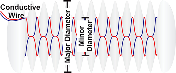
The minor diameters of the plastic bellows were wrapped with insulated conductive wire (red and blue). The inductance of the circuit measures the bellows’ length.
The joint was provided by Pneubotics (an Otherlab company, San Fransico, CA, USA, Fig. 1). The joint consists of two plates connected to four bellows spaced around a central steel cable. The centers of the bellows are kept at a fixed distance, designated b, of 4.9 cm from the central cable. The steel cable has a length h of 19.7 cm between the plates of the joint. It provides a “fulcrum” to convert the extension forces of the bellows into bending moments. The bellows have 26 major diameters between the plates of the joint. The major and minor diameters of the bellows are 6.7 cm and 4.9 cm, respectively. The joint is actuated by pressurizing the bellows with compressed air. The antagonized configuration of the four bellows creates a 2-DOF bending joint with independently controllable joint torque and passive stiffness. The unmodified joint has a range of motion of ±90 μ in each axis. In this work, the pressure in the bellows was maintained below 0.41 MPa.
The joint was outfitted with four distinct inductance circuits (Fig. 3). Pairs of adjacent circuits measured the bending in each half of the joint. The circuits were formed from “tinsel” wire with a high flex-fatigue life (TN3637, 1.14 mm outer diameter, resistance 538ohms/km, MN wire, St. Paul, MN, USA). The flexible wire was wrapped around 12 minor diameters of the bellows in the corresponding half. Each minor diameter had two turns of current (except at the ends of the circuits where there was only one turn). The inductance was measured with an LDC1614 chip (Excitation voltage: 1.2–1.8 V, Texas Instruments, Dallas, TX, USA). This chip measures the resonant frequency of four inductor-capacitor oscillating circuits in rapid succession. To this end, each inductive circuit was connected in parallel with a high-precision (1 %, NP0) 100 pF ceramic capacitor.
Fig. 3.
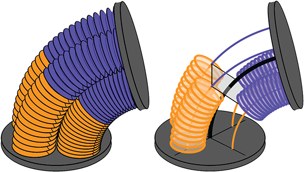
The deformation of the entire joint was approximated as the composition of two constant-curvature sections. Pairs of adjacent inductive sensor circuits (orange and blue circles) measured the bending of the each half independently. This “split-joint” configuration allows us to estimate the joint motion in non-uniform-curvature conditions.
To provide a ground truth reference for our sensor, the joint was mounted upside-down on a level mount such that the relative orientation of the ends could be measured with an IMU (Dynamic accuracy: ±1 μ, 3-Space Micro USB, magnetometer disabled, Yost Labs, Portsmouth, OH, USA). A 38cm arm was attached to the end of the joint for calibration and testing. Weights were added to the end of the arm to create different loading conditions. The pressure in the bellows was controlled with electronic pressure regulators (TR, Enfield Technologies, Shelton, GT, USA). The data acquisition and control was facilitated by LabVIEW.
3. Theory
3.1. Kinematic Model
The joint was modeled as the composition of two constant curvature sections (Fig. 3). This was designed to allow the deformation to be approximated even when the curvature across the length of the joint is not uniform.
For each constant-curvature section of the joint, the coordinate axes in the base frame originate at the center of the central cable and intersect with the bellows’ centers (Fig. 4). The x-axis points towards bellows 1, the y-axis towards bellows 2 and the z-axis along the central cable (when straight). The bellows’ centers are separated from the central cable by the constant distance b.
Fig. 4.
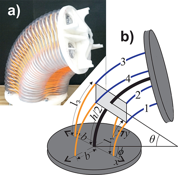
(a) Photo of a 2-DOF bellows-driven continuum joint. The orange fibers constrain the bellows around the central cable. (b) The kinematic model of the joint. Each half of the joint undergoes a bend angle 𝜃 with an orientation ϕ. The center of the joint is reinforced by a cable of length h (thick black line). The bellows are indexed from one to four. The center-lines of the half bellows (thin blue and orange lines) have lengths of l1, l2, l3 and l4. The centers of the bellows are spaced from the central cable by a distance b.
We describe the kinematics of each constant curvature section joint using a parametrization developed by author Thomas Allen. This parametrization has several desirable properties. It remains invertible in the straight configuration and has affine relationships between the rotation parameters and the lengths of the bellows. This parametrization is based on the two components, u and v, of a rotation vector ω=[u,v,0]T. The quantities u and v are the components of the rotation vector in the respective x and y directions. The z-component of the rotation vector is always zero. This rotation vector ω describes the orientation of the top of the plate relative to the base and is equivalent to rotating the top plate by an angle around the unit vector ω/||ω||. The rotation vector ω can also be described by the angles ϕ and θ
| (1) |
The homogeneous transformation from the base frame to a frame with distance h along the cable (assuming constant curvature across that distance) is given by the matrix g (u, v, h)
| (2) |
and the functions
| (3) |
These functions are defined even when 0 is zero. This is apparent from the Maclaurin series of sine and cosine.
The lengths l = f (u, v) of the half-bellows sections along their center-lines are expressed as follows:
| (4) |
Because h is fixed, the length l of each bellows section is a function of either only v or only u.
This model can also be derived from the enclosed bend angle θ and orientation of the bend ϕ.The length of a section of the central cable is a function of 0 and its radius of curvature p
| (5) |
Similarly, the length li of a bellows section is defined in terms of its radius of curvature ri and ɵ
| (6) |
The radii of the bellows sections are governed by the distance b from their centers to the central cable and the orientation of the bend (given by by the angle ϕ)
| (7) |
Multiplying Eq. (7) by θ yields Eq. (4).
The bending in the distal half of the joint was defined by ωα = [ua,va, 0]T and measured by the inductance values on the distal halves of bellows 1 and 2 (Fig. 3, blue). The proximal joint half was defined by ωb = [ub, vb, 0]T and measured with inductance sensors on bellows 3 and 4 (Fig. 3, orange).
3.2. Inductance Model
The inductive circuits are modeled as n circular coils of current connected electrically in series. Each circular coil is made up of N turns of wire. The total inductance L of the circuit is the sum of the self-inductance and mutual inductance Mi,j of the coils in the circuit. The total inductance is the sum of the elements in the inductance matrix L
| (8) |
The self-inductance of the individual coils does not change during actuation. A circular wire coil with N turns of current, a coil radius r and a wire radius a has a self-inductance that is approximated by
| (9) |
This approximation assumes that the current distribution is concentrated on the surface of the conductors. μ, is the magnetic permeability of the surrounding medium (approximately 4π × 10−7H/m for nonmagnetic materials such as plastic and air).
The sensitivity of the inductance to joint motion comes from the change in mutual inductance between coils on different minor diameters. For these current paths, the mutual inductance is calculated numerically by integrating the Neumann formula [22]. For two paths in 3D space
| (10) |
parameterized by si = [0,1], s2 = [0,1], the mutual inductance is given the double integral
| (11) |
The mutual inductance between two N-turn coils on separate convolutions was approximated as N2 times the mutual inductance between single-turn coils (circular loops) on the minor diameters of the bellows. This approximation is accurate when the distance between the turns in each coil is small relative to the distance between the two coils.
The inductance values of the circuits on the bellows change with the deformation of their corresponding joint section. For example, the inductance of a sensor on bellows 1 in the proximal half of the joint, L1a = f (ua,va), is a function of the curvature of the joint in that half. In order to measure the motion of the joint, we desire to invert this relationship (e.g. ua = f (L1a, L2a, L3a, L4a)). We used the kinematic and inductance models to investigate which combinations of inductance sensors are suitable for use in this inversion. To this end, Eq. (11) was used to calculate the inductance of the circuits at different joint orientations. A circular loop of current was first defined as a geometric path. This path was then transformed by Eq. (2) to the appropriate positions around the joint as it underwent constant-curvature bending. For each pair of circular loops in a circuit, Eq. (11) was integrated with the MATLAB integral2 function. To examine the effect of sensor placement, the sensors were modeled to be on the same section of the joint (i.e. with geometries dependent on ua and va). In this configuration, the length change of the sensor modeled on bellows 1 was equal and opposite of that on bellows 3. The same relationship holds for bellows 2 and 4.
The geometry and corresponding inductance values were calculated at each combination of a series of 22 values of ϕ and 12 values of θ. The values of ϕ were equally spaced between 0 ° and 343.64 ° and the values of θ where equally spaced between 0 ° and 90 °. The inductance values were calculated only once for θ = 0 (instead of 22 times for the 22 identical configurations of various ϕ values with θ = 0).
The modeled inductance values were used to evaluate four different sensor combinations. The first was a single-variable fourth-order polynomial regression of the length-changing rotation component against the modeled inductance of the sensor on bellows 1 (va = f (L1a)). The second regression was against the difference of the modeled inductance of the sensors on the antagonized pair, bellows 1 and 3 (va = f (L1a — L3a)). The third combination was a two-variable polynomial regression against the adjacent sensors on bellows 1 and 2 (va = f (L1a, L2a)). The final combination was a two-variable regression on the differences of each antagonized pair (va = f (L1a — L3a, L2a — L4a)). The residual error of these regression types is listed in Table 1.
Table 1.
Model Estimates of va with Sensor Combinations
| Polynomial Type (4th Order) | RMSE (°) | R2 |
|---|---|---|
| va = f (L1a) | 0.323 | 0.9997286 |
| va = f (L1a − L3a) | 0.149 | 0.9999421 |
| va = f (L1a, L2a) | 0.029 | 0.9999979 |
| va = f (L1a − L3a, L2a − L4a) | 0.020 | 0.9999990 |
The single-variable regression (va = f (L1a)) explained 99.97% of the variation in the corresponding rotation component (Fig. 5). The bulk of the remaining error comes from the variance introduced by the orthogonal rotation component (e.g. ua ). The second combination looked at the difference between the inductance values L1a and L3a. If ua were to effect L1a and L3a identically, the effect of ua would be canceled in the difference. Though the effect of ua on the two sensors is not identical, the regression against L1a —L3a did lower the RMSE by 54 % (va = f (L1a — L3a)). Including measurements from a sensor that primarily measures ua (va = f (L1a,L2a)) reduced the RMSE by an order of magnitude (compared to the single variable regression). A regression against the differences of both antagonized pairs only reduced the RMSE by an additional 30 %. The strategy of using two adjacent sensors on the same joint section (e.g. va = f (L1a,L2a)) is adopted experimentally in this work.
Fig. 5.
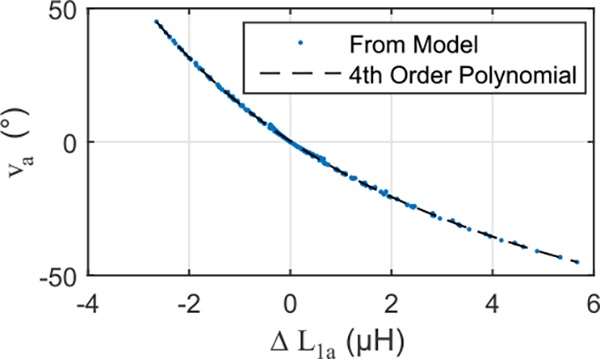
The results of the inductance model for the joint used in this work. Much of the variation in the rotational compnents (e.g. va) is explained by a simple polynomial regression against the inductance of a coil on the length-changing bellows (e.g. L1a).
3.3. Design Principles for Inductance Sensors on Bellows
Bellows-based inductance sensors exhibit the greatest sensitivity to motion when the minor diameters of the bellows are close together relative to the size of the diameters. Consider two coaxial circular wire coils of a single turn separated by a distance h’ along their mutual axis. If the coils are moved closer together, the mutual inductance between them increases.
The change in mutual inductance per distance traveled is also affected by the distance between the coils. The sensitivity of the mutual inductance to a change in distance is . Its magnitude is greatest when the coils are close together and declines rapidly as they move farther apart. For example, from an axial distance of h’ = .05 diameters to h’ = 1 diameter, the sensitivity decreases by approximately two orders of magnitude (Fig. 6).
Fig. 6.
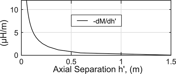
Shown is the mutual inductance sensitivity to the separation of two coaxial circles of equal diameter (1m) separated by a distance h’. The change in mutual inductance per distance traveled declines rapidly as the coils move farther apart.
Thus inductance sensors are best-suited to work on bellows with minor diameters that are spaced much more closely than the size of the diameters themselves. The bellows used in this work, for example, have h’ values of approximately 0.014 diameters when the joint is straight.
Another consideration is how many turns of wire to use in each coil. This consideration has trade-offs in sensor quality and actuation range. One measure of inductance sensor quality is the “Quality Factor” Q
| (12) |
where R is the resistance, L the inductance and fexcite the excitation frequency. The maximum excitation frequency is often limited by the sensing circuitry or parasitic capacitance [24]. Thus, for a given frequency, it is desirable to maximize the ratio of inductance to resistance. The inductance scales with the radius r of the coils and with the square of the number of turns N2 in each coil
| (13) |
The resistance is proportional to the number of turns N and the radius r of the circular coils and inversely proportional to the cross-sectional area of the conductor Awire
| (14) |
Accordingly, the inductance to resistance ratio scales linearly with the number of turns N and the crosssectional area of the conductors Awire
| (15) |
Thus, increasing the number of turns in each coil or increasing the cross-sectional area of the conductors increases the sensor quality. However, there are trade-offs to increasing these quantities. Increasing the number of turns can increase the parasitic capacitance which, if it becomes too high, can lower the feasible excitation frequency [24]. Furthermore, the wires take up physical space on the minor diameters. The cross-sectional area Acoil of the circular coils scales in the same way as
| (16) |
This bulk of material in the convolutions could limit contraction of the bellows. This also suggests that, for a fixed excitation frequency, a high quality factor is more easily achieved with a physically larger system. In this work, the number of turns of wire in each of the circular coils was kept at a minimum.
3.4. Measuring Non-uniform Curvature
When actuated against external loads, the joint may be subject to non-uniform internal bending moments. These may lead to non-uniform curvature along the length of the joint. Measuring the curvature of the joint in multiple sections can improve the ability of the joint to sense certain non-uniform-curvature deformations. To demonstrate how multiple sensing sections can improve the estimation of the joint motion, we simulated the lateral displacement of the joint end with no change in orientation of the plates (Fig. 7). The chosen displacement was selected to highlight the opportunity of using multiple sensors along the joint length.
Fig. 7.
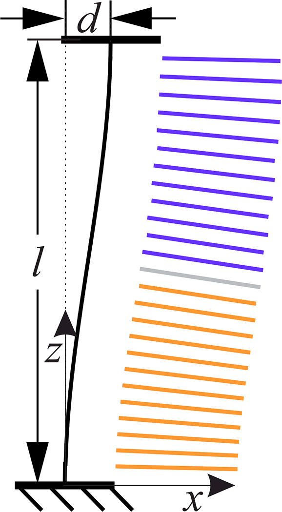
The geometry of the joint was simulated with a level displacement d. Our models predict that using two circuits along the length of the joint improves the estimation of deformations like these.
For this simulation, the profile of the central cable was approximated with the simple planar equations of a thin cantilever. The cantilever we considered has a fixed end and is free but guided at the other end. A force and moment at the free end deflect it a distance d without rotation at the tip. The profile of the cantilever with this deflection is given by the following expression [23]
| (17) |
where z is measured from the support along the length of the unloaded beam. l is the distance in z between the ends. l is selected to conserve the length of the central cable.
The geometry of the central cable and coils was calculated for a a lateral displacement of d =2 cm in the xz-plane along the x-axis towards bellows 1. The profile of the central cable was defined by Eq. (17). The geometric paths describing the circular loops of current were transformed via Eq. (17) to their positions in the displaced configuration (Fig. 7). The mutual inductance between the loops on bellows 1 was then calculated with Eq. (11) and the MATLAB integral2 function. Three different circuit configurations were modeled: one circuit spanning the entire bellows length (25 coils), two circuits (12 coils in each half) and three circuits (8–9-8, in each approximate third). The bending in each section was estimated by using the inductance values predicted for the lateral displacement in equations calibrated to constant-curvature bending. A single-variable, 4th-order polynomial (e.g. va = f (L1a)) was used for each circuit. The deformation of the total joint was then estimated by composing the curvatures predicted by the calibration equations in each section.
For this type of lateral displacement, using two circuits per length of the joint (compared to one) was predicted to lead to smaller error in the estimates of d, l and θ (Table 2). Three circuits was predicted to further reduce the errors in d and l.
Table 2.
Model-Predicted Error in Inductance-Based Estimates for a Lateral Displacement of 2 cm with θ = 0
| Variable | Number of Circuits | ||
|---|---|---|---|
| 1 | 2 | 3 | |
| d (mm) | −21.01 | −4.88 | −2.16 |
| −105% | −24.4% | −10.8% | |
| 1 (mm) | 1.22 | 0.46 | 0.22 |
| 0.62% | 0.23% | 0.11% | |
| 𝜃 (°) | 0.59 | −0.31 | −0.42 |
4. Experimental Evaluation
4.1. Calibration and Verification
The pressure P in each bellows is given by a base pressure Phasesure pbase and a relative difference in pressure ΔP to its antagonized counterpart. The pressure differences ΔP3 and ΔP2 are used because they actuate v and u respectively with a positive sign.
| (18) |
In this formulation, increasing the base pressure increases the passive joint stiffness. Increasing ΔP increases the torque about the corresponding axis. For a given joint-loading, base pressure and set of pressure differences, the joint will move until the torque from the pressure differences is balanced by the internal elastic forces of the joint and the external load.
The actuators were calibrated using a continuous 11 minute sequence of ΔP combinations. This resulted in well-distributed combinations of ΔP values (Fig. 8b). Pbase was 0.2 MPa.
Fig. 8.
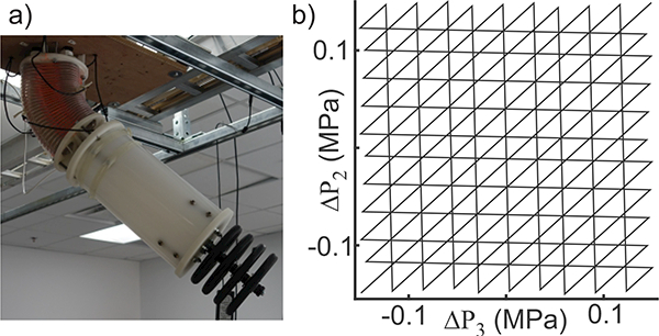
a) The joint was mounted upside-down on an elevated fixture. Mass was selectively added to the end of the arm for calibration and testing. Shown is a 9 kg of mass on the end of the arm. b) The combinations of ΔP were used to calibrate the joint.
The calibration data were concatenated from data collected with each of the following masses attached to the end of the arm (Fig. 8a): 0 kg, 2.3 kg, 4.5 kg, 6.8 kg, 9 kg. The purpose of the added mass was to create a variety of bending conditions for the calibration.
The IMU mounted on the distal plate of the joint provided ground truth measurements of the joint orientation. The IMU measurements were interpreted to find the components of a rotation vector by assuming the joint deformation to have constant curvature across its entire length. The inductance values from each joint half were regressed with two-variable, 4th order polynomials on and .
The pressure values in the bellows can be related to the steady-state angles of the joint with a given load (Fig. 9). Because the pressure in the calibration changed slowly, the dynamics of the joint can be neglected and the joint orientation data from the calibration can be considered steady-state for a given pressure value. The slope of a linear regression to the 0 kg pressure-orientation data was used to determine the gain for the feedback controller.
Fig. 9.
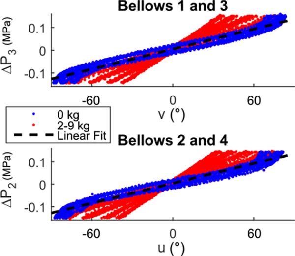
Shown are the pressure and orientation combinations recorded during the calibration. Because the pressure is being adjusted much slower than the joint dynamics, the relationship between the pressure and angle values shown here can be approximated as steady-state.
The calibration was verified against data taken in identical conditions that were not used in the calibration (Fig. 10). The inductance-predicted orientation of the joint was written as a unit vector in 3-space and compared to the orientation measured by the IMU. An inner product was used to determine the error (measured as a single angle) in the estimated orientation (Table 3). As predicted by our inductance models, including the data from the adjacent sensors improved the orientation estimates. Note that 3rd-order, two-variable polynomials resulted in an RMSE of 1.23 ° compared to 1.11 ° from the 4th-order polynomials.
Fig. 10.
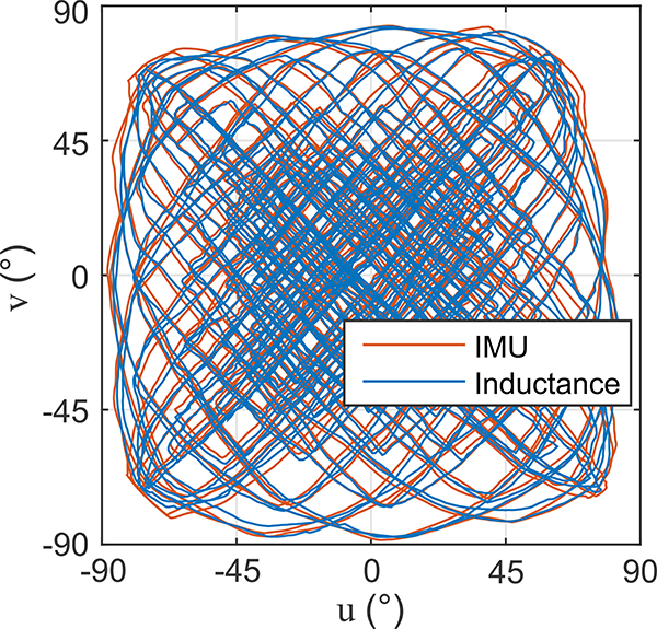
The rotation components from the verification data set of the joint calibration. The inductance sensors in each half of the joint were calibrated to predict the bending of the joint in that half. Combining the two halves resulted in an overall orientation estimate (blue). This closely matches the orientation measured by the IMU (red).
Table 3.
Experimental Verification of Calibration
| Polynomial Type (4th Order) | RMSE (°) | ||
|---|---|---|---|
| e.g. | va = f (L1a) | vb = f (L3b) | 1.76 |
| e.g. | va = f (L1a, L2a) | vb = f (L3b, L4b) | 1.11 |
4.2. Estimation of Lateral Displacement
The purpose of this experiment was to test the ability of the inductance sensors to estimate the end-position of the joint under pure lateral displacement. This type of deformation is unobservable by the IMU. The ground truth in position for this test came from optical markers tracked with an Optitrack VI20 Trio camera system (NaturalPoint, Corvalis, OR, USA). The ground truth in orientation came from the IMU. A string tied to the end of the joint was used to deflect the end of the joint towards bellows 1. The end of the joint was leveled by adjusting the bellows pressures until the IMU reported an approximately level configuration (Fig. 11). The resulting displacement between the ends of the joint was approximately 14 mm. Estimates of the joint displacement x and orientation v were calculated from the measured inductance values and the calibration identified in Section 4.1. The test was repeated three times.
Fig. 11.
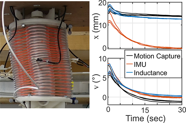
The photo shows the level joint with a forced, 14 mm displacement in the direction of bellows 1 (x). In this condition, the bending in one half of the joint is counteracted by bending in the other half. Also shown are the estimates of the lateral displacement x and the orientation v from the three lateral displacement tests. The lateral displacement predicted by the IMU (red) assumes the joint has a constant curvature across its entire length. As the angle of the joint approaches zero, the IMU displacement estimates (red) also approach zero. The inductance-predicted displacement (blue) remains close to the position recorded by the motion capture system (black). The inductance-predicted estimate of the orientation v also remains close to that measured by the IMU (most accurate).
Rom the onset of motion until the final level condition, the inductance provided accurate measures of the joint displacement and orientation (Table 4, Fig. 11). In the final condition, with the joint level and a displacement of 14 mm, the inductance estimate of v had an average error of 0.41 °. The inductance estimate of the displacement in x had an average error of −1.27 mm. The IMU estimate of x had an average error of −14.1 mm.
Table 4.
Average RMS of Estimation Error of Joint Deformation in the Lateral Displacement Tests
| Feedback Type | |||
|---|---|---|---|
| Estimate of | Period | IMU | Inductance |
| x(mm) | Entire Test | 12.10 (SD 0.38) | 1.05 (SD 0.19) |
| Final Condition | 14.1 (SD 0.25) | 1.27 (SD 0.15) | |
| v(°) | Entire Test | Ground Truth | 0.31 (SD 0.03) |
| Final Condition | Ground Truth | 0.41 (SD 0.07) | |
4.3. Feedback Control
The inductance sensors were tested in an orientation controller for the components of the rotation vector, u and v. The torque on the joint related to these respective orientation components comes from the pressure differences ΔΡ2 and ΔΡ3 (Eq. (18)). These torques are resisted by the bending stiffness of the joint materials and the external load. For the purposes of the feedback control, these resistive torques were considered unknown disturbances.
If the goal of this paper were to demonstrate the performance of the continuum joint, the pressure-orientation data from the calibration could have been used to generate a feedforward component in the control. However, our goal is to demonstrate the sensor performance. Accordingly, a control scheme was devised that relies only on feedback from the sensors without any feedforward compensation.
Our feedback controller adjusted the ΔΡ values based on the error between the measured and desired joint orientations. The architecture of our hardware relegates the low-level pressure control of ΔΡ to the proportional valves of the Electronic Pressure Regulators. Fundamentally, the joint-load system is similar to a second order system with an input torque (from the pressure difference) driving an inertial load. The response time of this pressure-load system is (depending on the loading of the joint) faster than or similar to the response time of the the low-level pressure control from the regulators. Accordingly, the step response of the system to a change in ΔΡ is often dominated by the dynamics of the pressure regulator and balanced by the resistive torques from the internal stresses and external loads. That is, when new pressure levels are prescribed, the system moves almost in tandem with the changing pressure levels to a new equilibrium position.
Accordingly, our feedback controller does not consider the ΔΡ values as torque inputs to the system but rather as equilibrium set points. These set points are adjusted with sensor feedback in an attempt to minimize the error e in each orientation component (u and v). This error is defined as the difference between the reference input (des) and the estimated values (est)
| (19) |
The dynamics of the prescribed pressure differences ΔΡ are controlled with proportional and derivative feedback gains. That is, the rate-of-change of the commanded pressure differences Δṗ depends on the scaled values of the error e and their time derivatives ė
| (20) |
The base pressure during the feedback control was the same as that used in the calibration (Pbase = .2 MPa) The controller gains were scaled by ap = 0.084 MPa/rad. ap is the slope of a line regressed on the calibration data (0 kg data only, Fig. 9) relating the outputs to the inputs (e.g. u to ΔΡ2). The complete control architecture is illustrated in Fig. 12.
Fig. 12.
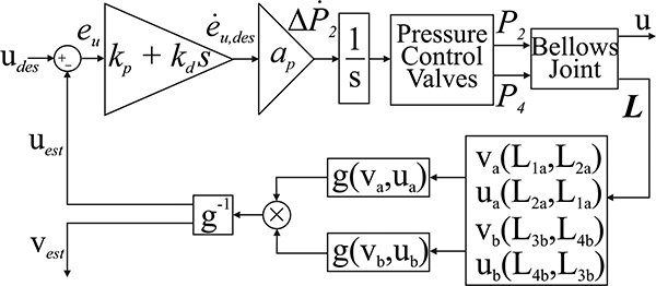
The feedback controller for the joint relied on the inductance-based estimates of the rotation components u and v. The performance of this controller was compared to one driven with feedback from the IMU.
The feedback was tested under two weight conditions 0 kg (kp = 2 sec−1, kd = 0 ) and 9 kg (kp = 2 sec−1, kd = 0.1 ). The gains were identified heuristically. The derivative gain used in the 9 kg case slowed the system response and was used to limit the reaction forces and ensure stability with the added inertia. The estimates of ė relied on a linear regression over the last 10 data points in time. The loop period of the LabVIEW-based controller was 15 ms. The reference input was a fixed, pseudo-random sequence of ten step changes in combinations of u and v. The levels of the steps were chosen to be feasible for the given weight condition (60 °, 30 ° and 0 ° for 0 kg; 25 °, 12.5 ° and 0 ° for 9 kg). The steps lasted for ten seconds each. The sequence of steps was repeated three times for each condition. The orientation recorded by the IMU was considered ground truth. For comparison, the controller was also tested with feedback from the IMU (instead of the inductance sensors). The same feedback gains and protocol were used in the IMU-controlled tests. The performance of the two feedback types was compared with a paired t-test (paired in each step).
There was a statistically significant difference in the tracking performance between the two types of feedback. The IMU feedback had, on average, 17 % less error in the steady-state with 0 kg and 22 % less error with 9 kg. The larger error with the inductance feedback (compared to IMU feedback) is expected because the IMU was used as the ground truth sensor. Overall, tracking performance with inductance feedback was comparable to that with IMU feedback (Fig. 13, Table 5).
Fig. 13.
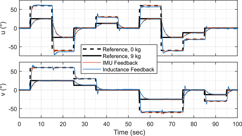
The data from the feedback control experiments. The dashed black line is the reference trajectory for the tests in the 0 kg weight condition. The solid black line corresponds to the 9 kg tests. The blue lines are the three inductance-feedback tests conducted in each weight condition. The tracking performance of the inductance feedback is comparable to that from the IMU (red lines).
Table 5.
Average RMS of Tracking Error (°) in Joint Orientation for Each Reference Step of Feedback Control Trials
| Feedbac k Type | t-test p |
|||
|---|---|---|---|---|
| Weight | Period | IMU | Inductance | |
| 0 kg | First 5 seconds | 13.53 (SD 5.99) | 13.79 (SD 6.02) | < 0.05 |
| Last 5 seconds | 2.48 (SD 1.55) | 2.98 (SD 1.46) | < 0.05 | |
| 9 kg | First 5 seconds | 8.18 (SD 3.70) | 8.10 (SD 3.55) | = 0.27 |
| Last 5 seconds | 1.02 (SD 0.61) | 1.30 (SD 0.55) | < 0.05 | |
5. Discussion
We developed a unique, inductance-based sensing system to measure and control the motion of bellows-driven continuum joints. This system is based on changes in mutual inductance between circular coils on the bellows. Verifying the calibration of our experimental sensing system on a separate data set resulted in an orientation error RMS of only 1.11 ° (Fig. 10). In contrast to an IMU, the inductance sensors can measure joint motion that does not change the relative orientation between the ends of a joint. A lateral displacement of 14 mm was measured by our system with only 1.3 mm of error. The rapid and accurate inductance measurements enabled a feedback controller to orient a 9 kg weight on a manipulator arm with a steady-state error of only 1.3 ° (3 ° with no weight). The performance of the inductance-based feedback controller was similar to an IMU-based controller which had a steady-state tracking error which was only 0.5 ° and 0.3 ° smaller in the respective 0 kg and 9 kg conditions.
Other sensing techniques have demonstrated more accuracy in similar systems. The “cable-like shape sensor” used in the 2017 FESTO “Bionic Motion Robot” reports a standard deviation of error in end-position estimation of 0.11cm for a 1 m long cable [17, 14]. Compared to the angle error of our calibration validation (RMS of 1.1 ° for an approximately 0.2 m sensor), their demonstrated accuracy is approximately an order of magnitude smaller. Moreover, their technique can measure curvatures that are much more complex than our two-sections of constant-curvature approximation.
Still, inductance sensing has advantages over other techniques. The sensor described in the previous paragraph relies on a helical flexible PCB populated with closely-packed LED and phototransistor pairs. Multiplexing the analog signals from all these pairs is complex and computationally expensive. Moreover, the physical bulk of this LED-based technique limits it to relatively large systems. The system used on the FESTO robot, for example, had a minimum bend radius of 10 cm [17]. The bend radius of Fiber-Bragg Grating curvature sensors is similarly limited. On the other hand, the inductance sensing technique proposed in this work scales with the size of the system. If the excitation frequency can be increased as the system size decreases, this scaling down can even be accomplished without a loss of sensor “quality” as measured by the quality. factor. This allows inductance sensing to measure the motion of continuum joints that would be difficult to measure by other methods.
This paper describes considerations for good sensor design. Inductance sensors for bellows will work best when the minor diameters of the bellows are relatively close together (compared to their diameters). Using many turns of low-resistance wire in the coils can boost the sensor quality factor. Boosting the quality factor in this way may come at the expense of a decreased range of motion in the system. Maintaining a high quality factor results in LC oscillators with a more “peaky” frequency response. This allows the sensors to better reject electromagnetic interference from, for example, sensors oscillating at different frequencies or electric motors in their proximity.
Future work could lead to additional understanding of inductance sensors for soft robots. The multisection, constant curvature technique developed in this work could be useful in applying inductance sensing to soft systems driven by bending bellows [10] or fiber-reinforced actuators [9, 11]. Future work could also consider the effect that internal twisting could have on the kinematics and estimation of the joint.
Based on the predictions of the inductance model, each half of our experimental joint relied on only two orthogonal sensors. However, using more sensors in a given joint section could improve the signal-to-noise-ratio and reduce the bias from external metals. Changes in the rotation component va, for example, create equal and opposite length changes in the corresponding sections of bellows 1 and 3. Accordingly, the sensitivity of a va sensor should approximately double when using the difference of L1a and L3a. Collecting data from redundant sensors on opposite sides of the joint could also allow the system to be accurate even if one side of the joint were in contact with a metal object (which can bias inductance measurements [10, 9]). If multiple inductance-sensing circuits were used in close proximity (e.g. on separate halves of the same bellows), active strategies could be necessary to prevent cross-talk [30].
The inductance-based sensors developed in this work bring sensing and control to otherwise difficult-to-sense continuum joints. Unlike discrete joints, continuum joints have no fixed center of rotation on which to affix an encoder. Alternative sensors proposed for continuum joints are often fragile, bulky or otherwise poorly-suited for diverse, real-world applications.
Self-sensing, bellows-driven continuum joints will enable e vulnerable. The sensing technology developed in thiss will provide inherently compliant actuation without backlash or stiction. Both the sensors and actuators can be made from lightweight and low-cost components. The flexible structure of the continuum joint will allow the robots to conform to external constraints. The absence of discrete mechanical joints in sensors or actuators will allow them to work in harsh environments where sliding surfaces would be vulnerable. The sensing technology developed in this work provides a critical step towards the full implementation of such robotic systems.
Acknowledgements
This material is based upon work supported by the National Science Foundation Graduate Research Fellowship under Grant No. DGE 1256260. Any opinion, findings, and conclusions or recommendations expressed in this material are those of the author(s) and do not necessarily reflect the views of the National Science Foundation. Funding for this project was provided by NIH (GRANT: 1-R01-EB019834–2014 Wearable eMbots to Induce Recovery of Function).
Biography
 Wyatt Felt is a Postdoctoral Fellow in at the Swiss Federal Institute of Technology in Lausanne (EPFL). He received a Ph.D. in Mechanical Engineering (August 2017) from the University of Michigan, Ann Arbor. There he was a National Science Foundation Graduate Research Fellow and worked under the direction of Prof. C. David Remy in the Robotics and Motion Laboratory (RAMlab). He received a B.S. in Mechanical Engineering in 2013 from Brigham Young University (BYU). Prior to his PhD, he worked as Head of Product Development at Owlet Baby Monitors (owletcare.com). More information is available at his personal website (wyattfelt.com). He has completed internships at the National Renewable Energy Laboratory and at iRobot Defense & Security (now Endeavor Robotics). Wyatt is a member of The Church of Jesus Christ of Latter-day Saints and served for 24 months (2008–2010) as a full-time volunteer for the church in the coastal regions of Ecuador.
 Maria J. Telleria is the CTO of Otherlab Pneubotics. She studied Mechanical Engineering at MIT where she received a B.S. (2008), M.S. (2010) and Ph.D. (2013).
 Thomas F. Allen is a Machine Vision Engineer at OpenSpace. During the time of this work, he was a Senior Robotics Engineer at Otherlab Pneubotics. He received a Ph.D. of Mechanical Engineering from Caltech (2016) and B.S. of Mechanical Engineering from the University of California, Berkeley (2005).
 Gabriel Hein is the VP of Automation at Otherlab Pneubotics. He has recieved B.S. (Auburn, 2007) and M.S. (University of California, Berkeley, 2010) degrees of Mechanical Engineering.
 Jonathan B. Pompa is a generalist at Otherlab Pneubotics. He holds degrees in Oceanography (M.S., University of California San Diego, 2005) and Mechanical Engineering (B.S., Carnegie Mellon, 1998).
 Kevin Albert is the founder and CEO of Pneubotics, an Otherlab company. Prior to his time at Otherlab, Kevin was an Advanced Robotics Engineer for Boston Dynamics where his responsibilities included creating control systems for “Big Dog” and “Alpha Dog.” He studied Mechanical Engineering at MIT (M.S., 2007) and Lehigh University (B.S., 2004).
 C. David Remy is an Assistant Professor of Mechanical Engineering at the University of Michigan, Ann Arbor. He received his Ph.D. from ETH Zurich, and holds both a M.Sc. in Mechanical Engineering from the University of Wisconsin and a Diploma in Engineering Cybernetics from the University of Stuttgart. Dr. Remy is the head of the Robotics and Motion Laboratory (ram-lab.engin.umich.edu). His research interests include the design, simulation, and control of legged robots, exoskeletons, and other nonlinear systems. Drawing inspiration from biology and biomechanics, he is particularly interested in the effects and exploitation of natural dynamic motions, the role of different gaits, and the possibility of force/torque controllable systems; both in conceptual models and in hardware realizations.
Footnotes
Disclosure of potential conflicts of interest.
Authors Wyatt Felt and C. David Remy are listed as inventors on a patent application for inductance sensing on bellows actuators. The other authors are (or were) employed by Pneubotics and/or its parent organization, Otherlab. Each of them has an investment interest with the company, and each is listed as an inventor in patents related to this work.
Compliance with Ethical Standards
This work was supported by the NSF and NIH.
Contributor Information
Wyatt Felt, Robotics and Motion Laboratory (RAMlab), University of Michigan, Ann Arbor, MI, wfelt@umich.edu, cdremy@umich.edu.
C. David Remy, Robotics and Motion Laboratory (RAMlab), University of Michigan, Ann Arbor, MI, wfelt@umich.edu, cdremy@umich.edu.
Maria J. Telleria, Pneubotics, an Otherlab Company, San Francisco, CA. info@pneubotics.com
Thomas F. Allen, Pneubotics, an Otherlab Company, San Francisco, CA. info@pneubotics.com
Gabriel Hein, Pneubotics, an Otherlab Company, San Francisco, CA. info@pneubotics.com.
Jonathan B. Pompa, Pneubotics, an Otherlab Company, San Francisco, CA. info@pneubotics.com
Kevin Albert, Pneubotics, an Otherlab Company, San Francisco, CA. info@pneubotics.com.
References
- 1.Amjadi Morteza, Kyung Ki-Uk, Park Inkyu, and Sitti Metin. Stretchable, skin-mountable, and wearable strain sensors and their potential applications: A review. Advanced Functional Materials, 2016. [Google Scholar]
- 2.Antonelli Keith and Immega Guy. An extensible robotic tentacle. Industrial Robot: An International Journal,24(6):423–427, 1997. doi: 10.1108/01439919710192545. URL 10.1108/01439919710192545. [DOI] [Google Scholar]
- 3.Bachmann ER, Duman I, Usta UY, McGhee RB, Yun XP, and Zyda MJ. Orientation tracking for humans and robots using inertial sensors. In Computational Intelligence in Robotics and Automation, 1999. CIRA ‘99. Proceedings 1999 IEEE International Symposium on, pages 187–194, 1999. doi: 10.1109/CIRA.1999.810047. [Google Scholar]
- 4.Bachmann ER, Yun Xiaoping, and Peterson CW. An investigation of the effects of magnetic variations on inertial/magnetic orientation sensors. In Robotics and Automation, 2004. Proceedings. ICRA ‘04. 2004 IEEE International Conference on, volume 2, pages 1115–1122 Vol.2, April 2004. doi: 10.1109/R0B0T.2004.1307974. [Google Scholar]
- 5.Cianchetti M, Ranzani T, Gerboni G, De Falco I, Laschi C, and Menciassi A. Stiff-flop surgical manipulator: Mechanical design and experimental characterization of the single module. In 2013 IEEE/RSJ International Conference on Intelligent Robots and Systems, pages 3576–3581, November 2013. doi: 10.1109/IR0S.2013.6696866. [Google Scholar]
- 6.de Vries WHK, Veeger HEJ, Baten CTM, and van der Helm FCT. Magnetic distortion in motion labs, implications for validating inertial magnetic sensors. Gait & Posture, 29 (4):535 – 541, 2009. ISSN 0966–6362. doi: 10.1016/j.gaitpost.2008.12.004. [DOI] [PubMed] [Google Scholar]
- 7.Felt Wyatt. Sensing methods for soft robotics, 2017. Univ. of Michigan, Rackham Graduate School. [Google Scholar]
- 8.Felt Wyatt and Remy C David. Smart Braid: Air muscles that measure force and displacement. In Intelligent Robots and Systems (IROS 2014), 2014 IEEE/RSJ International Conference on, pages 2821–2826. IEEE, 2014. [Google Scholar]
- 9.Felt Wyatt, Chin Khai Yi, and Remy C. David. Contraction sensing with Smart Braid McKibben muscles. Mechatronics, IEEE/ASME Transactions on, PP(99):1–1, 2015 ISSN 1083–4435. doi: 10.1109/TMECH.2015.2493782. [DOI] [PMC free article] [PubMed] [Google Scholar]
- 10.Felt Wyatt, Suen Michelle, and Remy C David. Sensing the motion of bellows through changes in mutual inductance. In Intelligent Robots and Systems (IROS 2016), 2016 IEEE/RSJ International Conference on IEEE, 2016. [Google Scholar]
- 11.Felt Wyatt, Chin Khai Yi, and Remy C. David. Smart Braid feedback for the closed-loop control of soft robotic systems. Soft Robotics, 2017. doi: 10.1089/soro.2016.0056. [DOI] [PMC free article] [PubMed] [Google Scholar]
- 12.Felt Wyatt, Lu Shihan, and Remy C. David. Modeling and design of “Smart Braid” inductance sensors for Fiber-Reinforced Elastomeric Enclosures. IEEE Sensors Journal, 18(7):2827–2835, April 2018. ISSN 1530–437X. doi: 10.1109/JSEN.2018.2802640. [DOI] [Google Scholar]
- 13.Festo. Bionic handling assistant, 2010. URL http://www.festo.com/cms/en_corp/9655_10218.htm.
- 14.Festo. BionicMotionRobot, Mar 2017. URL https://www.festo.com/group/en/cms/12747.htm.
- 15.Gaiser I, Wiegand R, Ivlev O, Andres A, Breitwieser H, Schulz S, and Bretthauer G. Compliant robotics and automation with flexible fluidic actuators and inflatable structures. 2012.
- 16.Gillespie MT, Best CM, and Kill-pack MD. Simultaneous position and stiffness control for an inflatable soft robot. In 2016 IEEE International Conference on Robotics and Automation (ICRA), pages 1095–1101, May 2016. doi: 10.1109/ICRA.2016.7487240. [Google Scholar]
- 17.Teichert Systemtechnik GmbH. Innovative cablelike-shape-sensor, Accessed April 2017. URL http://www.tst-inno.de/en/SAC.html.
- 18.Granosik G and Borenstein J. Integrated joint actuator for serpentine robots. Mechatronics, IEEE/ASME Transactions on, 10(5): 473–481, October 2005. ISSN 1083–4435. doi: 10.1109/TMECH.2005.856222. [DOI] [Google Scholar]
- 19.Grissom Michael D, Chitrakaran Vilas, Dienno Dustin, Csencits Matthew, Pritts Michael, Jones Bryan, McMahan William, Dawson Darren, Rahn Chris, and Walker Ian. Design and experimental testing of the octarm soft robot manipulator. In Defense and Security Symposium, pages 62301F–62301F. International Society for Optics and Photonics, 2006. [Google Scholar]
- 20.Ledermann Christoph, Mintenbeck Julien, Ding Yitao, Pauer Hendrikje, and Worn Heinz. Closed-loop control of a flexible instrument using an integrated FBG-based shape sensor. In International Conference on Advanced Technology & Sciences (ICAT’15), 2015. [Google Scholar]
- 21.Marchese AD, Komorowski K, Onal CD, and Rus D. Design and control of a soft and continuously deformable 2D robotic manipulation system. In Robotics and Automation (ICRA), 2014 IEEE International Conference on, pages 21892196, May 2014. doi: 10.1109/ICRA.2014.6907161. [Google Scholar]
- 22.Franz Ernst Neumann. Allgemeine gesetze der induzierten elektrischen strme. pages 1–87, 1845. [Google Scholar]
- 23.Jones Franklin D. Horton Holbrook L. Ryffel Henry H Erik Oberg Machinery’s Handbook (29th Edition) & Guide to Machinery’s Handbook. Industrial Press, 2012. ISBN 978-0-8311-2901-9. [Google Scholar]
- 24.Oberhauser, Chris at Texas Instruments. LDC Sensor Design, 2014. URL http://www.ti.com/lit/an/snoa930/snoa930.pdf.
- 25.Ochi Tatsuyuki. A positioning system for mobile robots using symmetrical rotating laser beams. Advanced Robotics, 4(3):217–222, 1989. [Google Scholar]
- 26.Penning RS, Jung J, Ferrier NJ, and Zinn MR. An evaluation of closed-loop control options for continuum manipulators. In Robotics and Automation (ICRA), 2012 IEEE International Conference on, pages 5392–5397, 2012. doi: 10.1109/ICRA.2012.6224735. [Google Scholar]
- 27.Rizzello Gianluca, Naso David, York Alexander, and Seelecke Stefan. A self-sensing approach for dielectric elastomer actuators based on online estimation algorithms. IEEE/ASME Transactions on Mechatronics, 2016. [Google Scholar]
- 28.Sareh Sina, Noh Yohan, Li Min, Ran-zani Tommaso, Liu Hongbin, and Althoefer Kaspar. Macrobend optical sensing for pose measurement in soft robot arms. Smart Materials and Structures, 24 (12):125024, 2015. [Google Scholar]
- 29.StretchSense. Stretchsense evaluation kit datasheet, June 2015. [Google Scholar]
- 30.Texas Instruments. Application Report: Using Multiple Sensors with LDC1000, 2014. URL http://www.ti.com/lit/an/snoa924/snoa924.pdf.
- 31.To C, Hellebrekers TL, and Park Yong-Lae. Highly stretchable optical sensors for pressure, strain, and curvature measurement. In Intelligent Robots and Systems (IROS), 2015 IEEE/RSJ International Conference on, pages 5898–5903, September 2015. doi: 10.1109/IROS.2015.7354215. [Google Scholar]
- 32.Xu Ran, Asadian Ali, Naidu Anish S, and Patel Rajni V. Position control of concentric-tube continuum robots using a modified jacobian-based approach. In Robotics and Automation (ICRA), 2013 IEEE International Conference on, pages 5813–5818. IEEE, 2013. [Google Scholar]
- 33.Yassin Ali, Nasser Youssef, Awad Mariette, Al-Dubai Ahmed, Liu Ran, Yuen Chau, and Raulefs Ronald. Recent advances in indoor localization: A survey on theoretical approaches and applications. IEEE Communications Surveys & Tutorials, 2016. [Google Scholar]
- 34.Yates Alan and Selan Jeremy. Positional tracking systems and methods, May 12 2016. US Patent 20,160,131,761.
- 35.Yuen Michelle C, Tonoyan Henry, White Edward L, Telleria Maria, and Kramer Rebecca K. Fabric sensory sleeves for soft robot state estimation. In Robotics and Automation (ICRA), 2017 IEEE International Conference on, pages 5511–5518. IEEE, 2017. [Google Scholar]
- 36.Zhao Huichan, O’Brien Kevin, Shuo Li, and Shepherd Robert F.. Optoelectronically innervated soft prosthetic hand via stretchable optical waveguides. Science Robotics, 1(1), 2016. doi: 10.1126/scirobotics.aai7529. [DOI] [PubMed] [Google Scholar]


