Biventricular implantable cardioverter‐defibrillator (CRT‐D) has been an established lifesaving treatment for patients with severely reduced cardiac function.1 Recently, defibrillation threshold (DFT) testing during implantation has been ignored due to its negative effects on cardiac function. However, DFT testing can be helpful for the appropriate management of defibrillators.
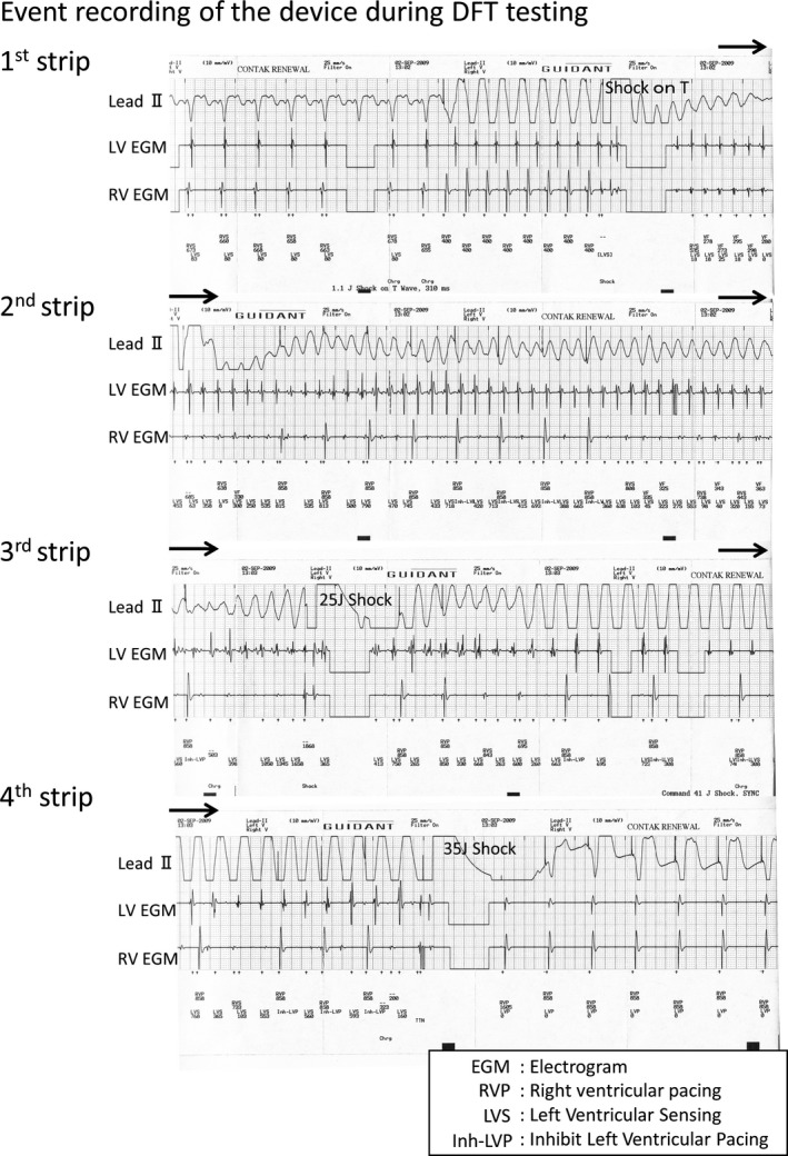
A 42‐year‐old man with a hemodialysis shunt on his left arm was referred to our hospital for advanced management of his heart failure. He presented with NYHA class III heart failure and had a history of syncope. Baseline electrocardiogram presented wide QRS complex with 140 ms and echocardiography showed reduced left ventricular ejection fraction (LVEF) of nearly 30%. He was diagnosed as having dilated hypertrophic cardiomyopathy by cardiac biopsy and had been taking Carvedilol 10 mg/d, Amiodarone 200 mg/d, and Pimobendan 5 mg/d. He underwent CRT‐D implantation on his right chest wall under general anesthesia. We placed DF‐1 shock lead in the apex of the right ventricle (RV) and bipolar CS lead in the posterolateral branch. The intrinsic amplitude of the RV and LV during sinus rhythm was 8.4 and 3.8 mV, respectively. The leads were connected to CRT‐D Model H197 (Boston Scientific, Marlborough, MA). The procedure was uneventful, and we performed DFT testing just before closing the wound. Ventricular fibrillation (VF) was induced by a small shock on T wave. Figure 1 shows the event recording of the device during DFT testing. This recording is not a continuous one. After 15 seconds, the device delivered 25 J shock, but ventricular tachycardia (VT) continued (Figure 1, 3rd strip). The device did not detect it, thus we delivered 35 J shock manually, which successfully terminated VT (Figure 1, 4th strip) and took about 60 seconds. Hence, why did this undersensing happen and how should we manage this problem?
Figure 1.

Event recording by cardioverter‐defibrillator (CRT‐D) Model H197 (Boston Scientific, Marlborough, MA) during DFT testing. (This recording is not a continuous one.)
INTERPRETATION
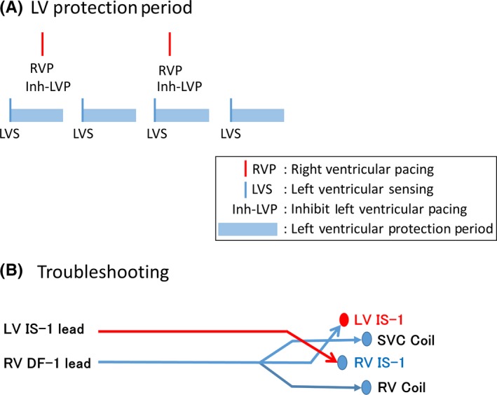
In this case, the amplitude of the RV dramatically decreased during VF (Figure 1, 1st strip). CRT‐D manufactured by Boston Scientific have the special feature to sense LV electrogram during VT/VF. Initially, the induced VF seemed to accompany RV and LV signals in a one‐to‐one fashion (Figure 1, 1st strip). Gradually, the RV signals became less frequent than the LV signals, which might be understood with the irregular conduction from LV to RV. RV signals were occasionally undersensed and back‐up RV pacing was delivered (Figure 1, 2nd strip). You may see the marker “Inh‐LVP” on the strip, which means that the LV pacing is inhibited (Figure 1, 2nd‐4th strip). CRT‐D devices manufactured by Boston Scientific have their original timing cycle called ‘Left ventricular protection period (LVPP)’. As illustrated in Figure 2A, LVPP is set after LV sensing or LV pacing for 400 ms. LV pacing is inhibited during this period. The purpose of LVPP is to inhibit the LV pacing during the vulnerable period of LV. In this case, the device sensed frequent LV signals and LV pacing was inhibited through the tachycardia event. Although it took longer than usual to detect VF due to undersensing, the device finally delivered the 25 J shock (Figure 1, 3rd strip). However, VF turned to an organized VT and continued. Spontaneous RV electrogram could be seen during the VT, which might be also understood with the irregular conduction from LV to RV. The device had no means to detect VT based on RV electrogram. We delivered 35 J shock manually, which restored the sinus rhythm (Figure 1, 4th strip).
Figure 2.

A, Left ventricular protection period. B, Troubleshooting of this case. LV lead was plugged to the RV IS‐1 port and vice versa (RV IS‐1 to the LV IS‐1 port)
Figure 2B illustrates the troubleshooting we performed. To utilize the LV signals to detect VT/VF in this case, we plugged the LV lead to the RV IS‐1 port and vice versa (RV IS‐1 to the LV IS‐1 port) (Figure 2B). We were lucky to use the DF‐1 lead for the RV shock lead, which has three arms to plug to the device: RV‐1, SVC coil, and RV coil. Although we did not try to induce VT/VF again, we believe that the undersensing of VT/VF does not happen again under this situation because the LV signal was excellent during VF and the DFT of a long duration VF is higher than that of a short duration VF.2, 3, 4
Implantable cardioverter‐defibrillators (ICDs) or CRT‐Ds utilize RV electrogram to detect VT or VF. The special feature to sense LV electrogram during VT/VF helped us to understand the rare phenomenon; “dissociated activation between the ventricles” in this case. Fortunately, we performed DFT testing on this case. DFT testing had been a routine practice during implantation a decade ago. However, the concern that shock itself deteriorates a patients’ prognosis arose.5 Recently, the prospective trial, “SIMPLE trial,” has revealed that the implantation of the devices without DFT testing does not increase the mortality of the patients,6 which suggested that DFT testing can be omitted safely. However, we still had a good reason to perform DFT testing on this case because the device was implanted on the right side and the patient was taking amiodarone, which might elevate DFT.7, 8 Originally, DFT testing has two important roles: to check the safety margin of defibrillation and to check the appropriate detection of VT/VF. In this case, the amplitude of the RV signal dramatically decreased during VT/VF and undersensing of the VT/VF occurred. We could not tell the amplitude of the signals during VT/VF without DFT testing. The amplitude during the sinus rhythm and that during VT/VF can be far apart. In this case, we could manage this problem easily because we found it before closing the wound. Dissociated activation during VT between the ventricles is a rare phenomenon and difficult to be found. As far as we know, this is the first report clearly showing the proof of the dissociation. We tried to duplicate this phenomenon later on the next day under transient intravenous anesthesia, but we could not. The phenomenon seemed to be situation dependent.
In this case, we could not obtain the safety margin of DFT; 10 J. Maximum shock of 35 J successfully terminated VF, however, 25 J shock failed to terminate left side VF. It took too much time to manage sensing issues and we anticipated the better DFT under the early detection of VF without undersensing. Although changing the position of the lead could be the choice, we did not dare to try another position to minimize the operation time and the surgical stress.
CONCLUSION
Dissociated activation between the ventricles during VT led to undersensing by a CRT‐D. The feature to display LV electrogram during VT/VF was helpful for the correct understanding and the prompt troubleshooting in this case. Although it is a rare phenomenon, we have to reconsider the value of DFT testing.
CONFLICT OF INTEREST
The authors declare no conflict of interests for this article.
REFERENCES
- 1. Bristow MR, Saxon LA, Boehmer J, et al. Cardiac‐resynchronization therapy with or without an implantable defibrillator in advanced chronic heart failure. N Engl J Med. 2004;350:2140–50. [DOI] [PubMed] [Google Scholar]
- 2. Liqun Wu, Jin Qi, Zhang Ning, et al. The effects of acute amiodarone on short‐ and long‐duration ventricular defibrillation threshold in canines. J Cardiovasc Pharmacol. 2011;58:432–8. [DOI] [PubMed] [Google Scholar]
- 3. Dosdall DJ, Osorio J, Robichaux RP, Huang J, Li L, Ideker RE. Purkinje activation preceds myocardial activation following defibrillation after long‐duration ventricular fibrillation. Heart Rhythm. 2010;7:405–12. [DOI] [PMC free article] [PubMed] [Google Scholar]
- 4. Windecker S, Ideker RE, Plumb VJ, Kay GN, Walcott GP, Epstein AE. The influence of ventricular fibrillation duration on defibrillation efficacy using biphasic waveforms in humans. J Am Coll Cardiol. 1999;33:33–38. [DOI] [PubMed] [Google Scholar]
- 5. Poole JE, Johnson GW, Hellkamp AS, et al. Prognostic importance of defibrillator shocks in patients with heart failure. N Engl J Med. 2008;359:1009–17. [DOI] [PMC free article] [PubMed] [Google Scholar]
- 6. Healey JS, Hohnloser SH, Glikson M, et al. Cardioverter defibrillator implantation without induction of ventricular fibrillation: a single‐blind, non‐inferiority, randomised controlled trial (SIMPLE). Lancet. 2015;385:785–91. [DOI] [PubMed] [Google Scholar]
- 7. Friedman PA, Rasmussen MJ, Grice S, Trusty J, Glikson M, Stanton MS. Defibrillation thresholds are increased by right‐sided implantation of totally transvenous implantable cardioverter defibrillators. Pacing Clin Electrophysiol. 1999;22:1186–92. [DOI] [PubMed] [Google Scholar]
- 8. Cheng Z, Turakhia M, Lo R, et al. Incidence and clinical predictors of low defibrillation safety margin at time of implantable defibrillator implantation. J Interv Card Electrophysiol. 2012;34:93–100. [DOI] [PubMed] [Google Scholar]


