

Abstract
Tissue engineered menisci hold promise as an alternative to allograft procedures but require a means of robust fixation to the native bone. The insertion of the meniscus into bone is critical for meniscal function and inclusion of this soft tissue-to-bone interface in a tissue engineered implant can aid in the fixation process. However, the native insertion is characterized by gradients in composition, tissue architecture, and cellular phenotype that are difficult to replicate. In this study, we tissue engineered a soft tissue-to-bone interface with a cellular gradient of fibrochondrocytes and mesenchymal stem cells and subjected this construct to a biochemical gradient through a custom media diffusion bioreactor. These constructs, consisting of interpenetrating collagen and boney regions, displayed improved mechanical performance and collagen organization compared to controls. Media gradient exposure produced tissue engineered morphologies that appear similar to native. Collectively these data show that cellular and biochemical gradients improve integration between collagen and bone in a tissue engineered soft tissue-to-bone constructs.
Keywords: enthesis, co-culture, tissue engineering, interface
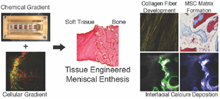
Graphical Abstract
A tissue engineered meniscal insertion was generated using compositional, cellular, and chemical gradients. Constructs were subjected to chemical and mechanical conditioning through custom bioreactor. Utilization of cellular and chemical gradients resulted in constructs with localized interfacial structuring, collagen fiber development, and improved mechanical performance with respect to controls.
1. Introduction
The menisci, fibrocartilaginous structures located between the tibia and femur, are crucial for normal knee function. Healthy menisci aid in proper load distribution, as well as cushioning and lubrication within the knee joint.[1] Meniscal lesions are the most common intra-articular knee injury, with over one million reparative surgeries performed annually in the United States.[1,2] Current surgical procedures commonly involve transplantation of a meniscal allograft, cadaveric tissues consisting of the meniscal body and its osseous transitional regions or entheses.[3] The entheses allow for transosseous fixation of the allograft, providing a stable attachment point for the implant.[4] Despite the success of many meniscal allograft transplants, these procedures still suffer from a lack of donor tissue and mismatched geometries between donor and patient.[5] Emerging alternative treatment options include tissue engineered menisci, which can provide a solution for these limitations.
Creation of a tissue engineered meniscus requires the inclusion of the enthesis, a complex tissue structure consisting of multiple compositional, structural, and mechanical gradients generated through a gradient in cellular phenotype. The meniscal enthesis consists of a fiber-containing region that shifts into unmineralized and then mineralized fibrocartilage before reaching the underlying bone.[6–8] Recreating this structure synthetically requires a method for establishing these compositional, chemical, and cellular gradients.[7] Previously developed scaffolds have created compositional gradients by combining multiple biomaterial layers into a single construct or establishing mineral gradients through mineral growth within a single scaffold.[4,9–12] Chemical gradients have been imposed on scaffolds through the use of diffusion systems to engineer zones of mineralization and to influence cell behavior.[13,14] Gradients in cellular phenotype can accentuate the effects of applied chemical gradients and aid in the matrix remodeling process.[10,15] To date, however, combinations of these methods to generate simultaneous compositional, chemical, and cellular gradients as a means of enhancing integration has yet to be fully explored in the context of interfacial tissue engineering.
Recreating the diversity of cell types present in native tissue is particularly challenging. For example, the meniscus contains fibrochondrocytes (FCCs), whereas the boney regions of the enthesis contain osteoclasts, osteoblasts, and osteocytes. A gradient of these different cell types exists in the intermediate enthesis regions. To circumvent the necessity for seeding numerous cellular phenotypes into a single scaffold, some designs have relied on the differentiation capacity of mesenchymal stem cells (MSCs).[16,17] Mesenchymal stem cells have been widely used in enthesis tissue engineering due to their therapeutic potential, ease of isolation, and propensity for collagen deposition.[18] Additionally, MSCs are the progenitors for the various phenotypes present in the enthesis, and MSCs are known to differentiate towards these phenotypes through exposure to various growth factors.[19]
We have previously developed a model system to tissue engineer the meniscus-to-bone interface.[20] Our system utilizes FCC-seeded collagen gel infiltrated into decellularized trabecular bone, generating a multi-region scaffold consisting of soft tissue and boney regions. We initiated fiber formation during culture through the addition of mechanical boundary conditions, causing the FCC population to reorganize the collagen in the soft tissue region into structures containing organized fibers.[20] Despite the generation of a multi-region scaffold with many similarities to native tissue, these constructs lacked the graded complexity present at the interface of soft tissue and bone in the native meniscal enthesis.
We hypothesize that we can achieve robust integration at the tissue engineered construct’s soft tissue-to-bone interface through the inherent differentiation capacity of the MSCs and the introduction of regionally dependent biochemical stimuli. To test this hypothesis, we developed new methods to introduce cellular and chemical gradients into tissue engineered scaffolds. We fabricated constructs with MSCs localized in the boney region and FCCs localized in the soft tissue region, generating a cellular gradient. Furthermore, we designed a bioreactor to deliver specific media to the bone and soft tissue portions of the constructs individually, thereby subjecting the constructs to a chemical gradient. Characterization of these constructs revealed collagen fiber formation in the soft tissue portion of the construct, calcium deposition at the interface of the soft tissue and bone portions, and overall improvement in mechanical performance with respect to controls.
2. Results
To study the effects of applying cellular and chemical gradients to a tissue engineered meniscus-to-bone interface, three groups were generated: Control, Cellular Gradient, and Cellular & Chemical Gradient (Figure 1b). The Control group replicated our previously published tissue engineered meniscus-to-bone interface, fabricated by injecting a cell-seeded collagen gel into a decellularized bone plug. Briefly, this construction generated a multi-region scaffold consisting of FCC-seeded collagen gel and interpenetrating FCC-seeded collagen gel and decellularized bone (Figure 2b).[20] The Cellular Gradient group utilized the addition of MSCs seeded onto the bone plugs prior to injection of the FCC-seeded collagen gel, generating a cellular gradient between FCCs in the soft tissue region of the construct and MSCs in the boney region (Figure 2b Interface). The Cellular & Chemical Gradient group had an additional gradient in media types applied to the constructs through a custom bioreactor (Figure 2a).
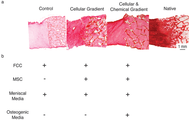
Figure 1.
(A) Picrosirius red stained histological sections (left to right) Control, Cellular Gradient, Cellular & Chemical Gradient, and Native meniscal entheses. (B) Cellular and media constituents of each tissue engineered construct group. Plus (+) indicates presence of media or cell type during culture of the corresponding group in A. Minus (−) indicates absence of media or cell type.
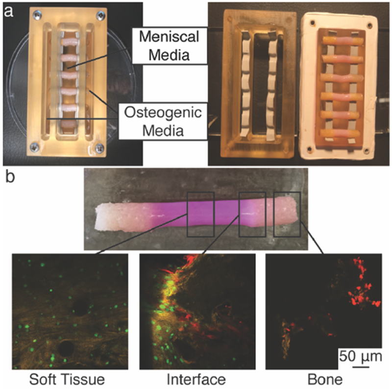
Figure 2.
Development of spatial gradients in tissue engineered meniscal entheses. (A) Polysulfone trichamber diffusion bioreactor used to create chemical gradients during culture of meniscal enthesis constructs. Fully assembled bioreactor with 6 constructs (left). Disassembled to show top and bottom components sealed with silicone rubber tape (right). (B) Photograph of engineered construct removed from bioreactor (top). Confocal microscopy images of cellular gradients in 0-week co-culture constructs (bottom). FCCs (green) were seeded into the soft tissue region (Soft Tissue) and MSCs (red) onto the bone (Bone). Both cell types were present in a gradient at the interface of collagen and bone (Interface).
Constructs from all groups were clamped at the bony ends during culture.[20] The Control and Cellular Gradient constructs were cultured in a clamping bioreactor with meniscal media (Figure S1b). For the Cellular & Chemical Gradient group, a tri-chamber bioreactor (Figure 2a) was constructed to simultaneously apply mechanical boundary conditions and generate a chemical gradient at the soft tissue-to-bone interface of the constructs; the point where the FCC-seeded collagen gel meets the MSC-seeded bone plug. The boney region of the construct was cultured in osteogenic media, while the soft tissue region of the construct was cultured in meniscal media. Diffusion tests of the bioreactor using a dye showed that the boney portion of the construct is sufficient to create diffusive conditions between the chambers of the bioreactor (Figure S2). Thus, we can conclude the interfacial portion of the construct is subjected to inverse gradients of meniscal and osteogenic media. Constructs for each of these groups were cultured for four weeks under these conditions.
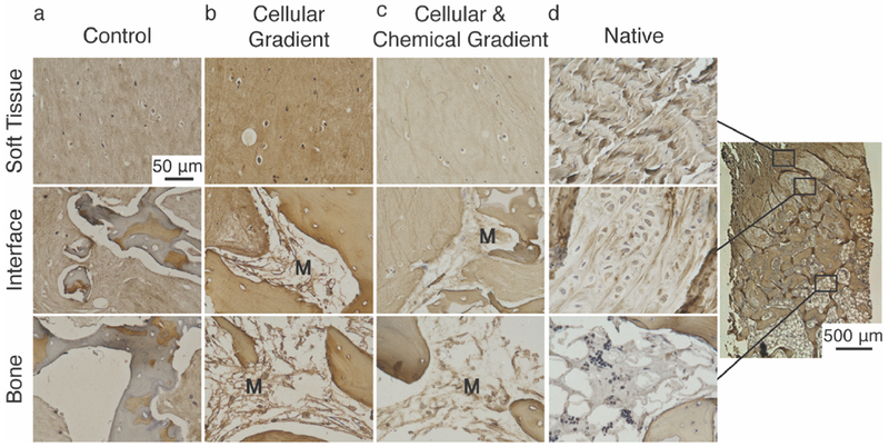
Successful establishment of a cellular gradient across the soft tissue-to-bone interface in the Cellular Gradient and Cellular & Chemical Gradient groups was demonstrated by fluorescent labelling of cells (Figure 2b). MSCs lined the trabeculae of the bone, while FCCs were evenly dispersed throughout the collagen gel. Both cell types were present at the interface (Figure 2b Interface). Histological analysis reveals we attained a similar tissue morphology in the Cellular & Chemical Gradient group to that found in native (Figure 3). The native enthesis shows fibroblastic-like cells embedded between fibers in the soft tissue region of the enthesis (Figure 3a Soft Tissue). We observed similar behavior in the Cellular & Chemical Gradient group and to a lessened degree in the Control and Cellular Gradient groups (Figure 3b-d Soft Tissue). Use of FCCs in the soft tissue region resulted in a more rounded phenotype versus the native tissue. However, we still observed the development of a fiber-like morphology, and the use of FCCs allowed for production of meniscus-like tissue, which is beneficial for the given application. Neither the addition of the cellular nor chemical gradients had any visible effect on the shape of the FCCs (Figure 3b-d Soft Tissue). Addition of a cellular gradient into our tissue engineered enthesis constructs resulted in the production of a collagenous matrix lining the surfaces of the trabeculae (Figure 3c, 3d Interface). This matrix was deposited by the MSCs and was present prior to the injection of the collagen gel (Figure S1c). We did not observe the development of the interfacial, cartilaginous matrix, present in native (Figure 3a Interface), but the MSC-deposited matrix in both groups containing the cellular gradient appeared to interface closely with the injected collagen gel, indicating interaction between these two matrices (Figure 3c, 3d Interface). The matrix deposited by the MSCs in the groups containing cellular gradients appeared morphologically similar to bone marrow, present in native tissue (Figure 3a, d Bone). The MSCs in the Cellular & Chemical Gradient group displayed an elongated phenotype, whereas the MSCs in the Cellular Gradient group exhibited a rounded phenotype (Figure 3c Bone). This matrix is not present in the Control group, due to the lack of MSCs (Figure 3b Interface, Bone).
Figure 3.
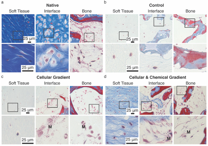
Masson’s Trichrome staining of (A) Native, (B) Control, (C) Cellular Gradient, and (D) Cellular and Chemical Gradient meniscal entheses at (left to right) soft tissue, interface, and bone regions. Boxes indicate region magnified in image below. M denotes presence of MSC-deposited matrix in Cellular Gradient and Cellular & Chemical Gradient groups. Blue and red staining highlight morphological changes in collagen gel and bone. Light red or pink staining indicates cytoplasm. Dark purple/black staining indicates cell nuclei.
Examination of the soft tissue region of the constructs showed an apparent increase in collagen density and alignment in the groups containing a cellular gradient versus the Control group, with the highest density and alignment observed in the Cellular & Chemical Gradient group (Figure 1a, 4). The development of collagen fibers was noted in all groups in the soft tissue region of the constructs (Figure 4a-c). However, fibers in the Cellular & Chemical Gradient constructs appeared larger and more uniform than in either of the other groups (Figure 4c). These fibers also appeared to integrate with the trabeculae at the soft tissue-to-bone interface (Figure 1a).
Figure 4.
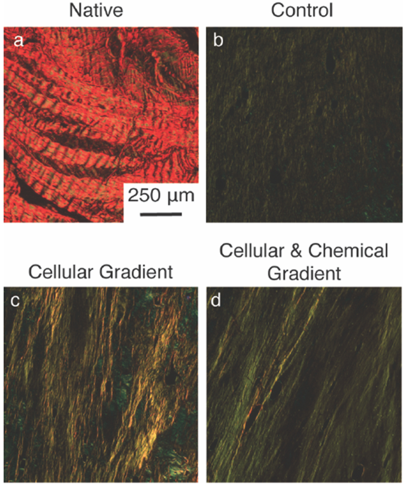
Picrosirius red stained sections within the soft tissue region of (A) Native, (B) Control, (C) Cellular Gradient and (D) Cellular & Chemical Gradient meniscal entheses viewed under polarized light to visualize collagen fiber organization.
Given the variety collagen types present across the native enthesis, immunohistological staining was performed to examine the distribution of these collagen types across the different regions of the constructs. Collagen type I stained positive in the collagen gel and trabeculae of all three tissue engineered groups, as was expected (Figure 5a-c). Staining is also present in the collagen gel and trabeculae of the native enthesis (Figure 5d). Additionally, positive staining of collagen type I was observed in the MSC-deposited matrix for the constructs containing cellular gradients (Figure 5b, 5c). The fibrocartilaginous tissue of the native enthesis, present between mineralized and unmineralized tissue, shows minimal staining for Collagen type I (Figure 5d). Collagen type II stained positive in FCC-seeded collagen gel of all three groups and in portions of the trabeculae (Figure 6a). Collagen type II was negative in the MSC-deposited matrix of both groups containing cellular gradients (Figure 6a). In the native enthesis, collagen type II staining appeared to be localized to the transitional, uncalcified cartilage region (Figure 6a Native). Collagen type X staining was positive in the FCC-seeded collagen gel of all three groups (Figure 6b). Collagen type X staining was also positive in the MSC-deposited matrix of the groups containing cellular gradients with a higher degree of staining near the interface between the soft tissue and boney regions of the constructs (Figure 6b). The bone marrow of the boney phase of the native enthesis also stained positive for collagen type X (Figure 6b Native). In the Cellular & Chemical Gradient constructs, collagen type II and type X staining intensity decreased into the boney region of the construct, indicating a localization of collagen type X at the interface (Figure 6b).
Figure 5.
Immunohistochemical staining for spatial distribution of collagen type I within (A) Control, (B) Cellular Gradient, (C) Cellular & Chemical Gradient, and (D) native meniscal entheses. Representative images were taken of soft tissue, interface, and boney regions. M denotes presence of MSC-deposited matrix. Far Right: Low magnification image of native meniscal enthesis.
Figure 6.
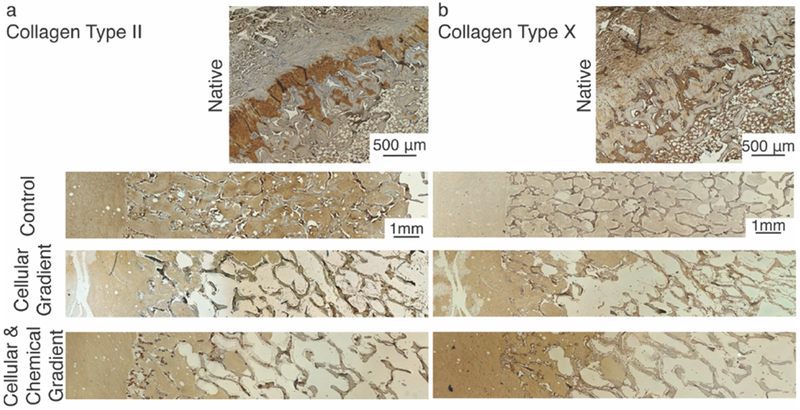
Immunohistochemical staining for spatial distribution of (A) collagen type II and (B) collagen type X within native, Control, Cellular Gradient, and Cellular & Chemical Gradient meniscal entheses. Localized type II collagen staining in the trabeculae of tissue engineered constructs is likely due to the age of the animal from which the bone plugs were collected.
To gauge whether MSCs in the boney regions of the constructs deposited new mineral, the bone plugs were labeled with Calcein, a dye that binds to calcium, prior to seeding and labeled with Calcein Blue, another calcium-specific dye, after the full culture period of four weeks. New Calcein blue-positive matrix indicating new calcium deposition was present in the collagen at the soft tissue-to-bone interface of both cellular gradient groups, while no new calcium deposition was observed in the Control group (Figure 7a-c Interface). Additionally, no new calcium deposition was observed in the soft tissue region of constructs for any group, indicating that the effect was localized to the boney regions of the constructs (Figure 7b, 7c Soft Tissue).
Figure 7.
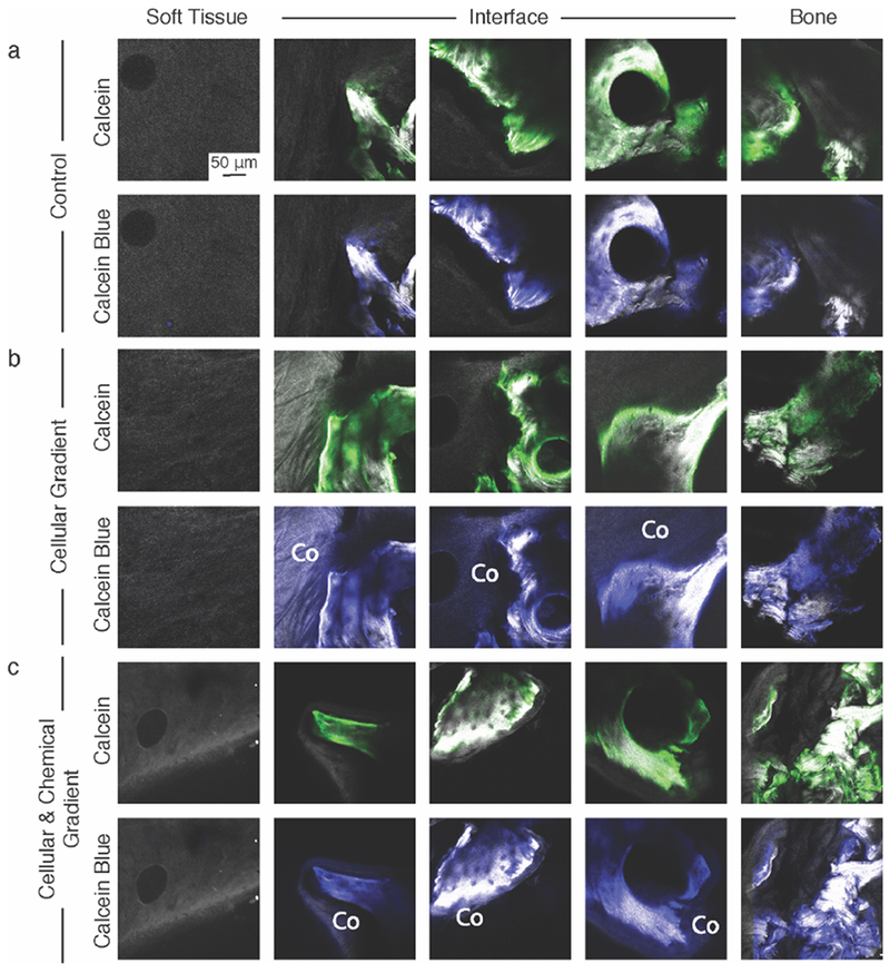
Second Harmonic Generation (SHG)/Two Photon Excited Fluorescence (TFEP) images of (A) Control, (B) Cellular Gradient, and (C) Cellular & Chemical Gradient constructs labelled with Calcein (green) prior to culture and Calcein blue after being removed from culture to identify new calcium deposition. Co denotes collagen that was positive for Calcein blue, but not Calcein and thus indicates new calcium. SHG-only images are available in Figure S4.
To measure the mechanical performance of the different groups, tensile tests to failure were performed. Tensile tests were chosen, as the native meniscal enthesis is primarily loaded in tension.[1] Constructs containing cellular gradients showed increased stiffnesses with respect to the Control group (Figure 8a). The elastic modulus significantly increased in the Cellular Gradient group by more than 350% compared to Control (p<0.05) (Figure 8a). The ultimate tensile strength of the Cellular & Chemical Gradient constructs significantly increased by more than 300% compared to Control (p<0.05) (Figure 8b). The effects of establishing a chemical gradient in conjunction with a cellular gradient significantly increased resilience of the Cellular & Chemical Gradient group over the Cellular Gradient group by over 150% and the Control group by over 300% (p<0.05) (Figure 8d). No significant differences in ultimate strain were observed between the groups (Figure 8c).
Figure 8.
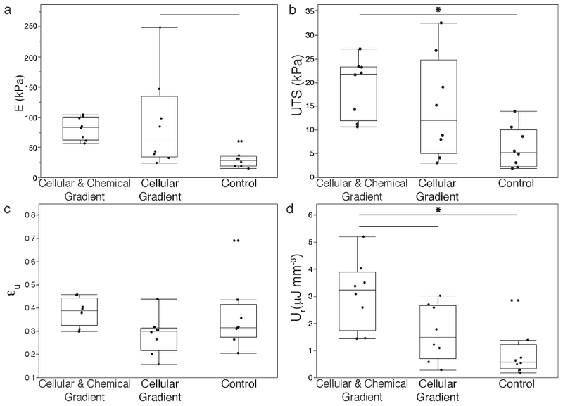
Uniaxial tensile pull to failure testing results of tissue engineered meniscal enthesis constructs to evaluate (A) Elastic modulus (E), (B) ultimate tensile strength (UTS), (C) ultimate strain (εu), and (D) modulus of resilience (Ur). Significantly different p < 0.05 (—), p < 0.01 (*), n=8.
3. Discussion
The current study builds upon and adds complexity to our previously established soft tissue-to-bone scaffold system, which lacked the interfacial complexity that exists in the native enthesis.[20] This complexity derives in part from the diversity of spatially distributed cellular phenotypes. We hypothesized that addition of MSCs to the scaffold would recapitulate this interfacial structure through localized MSC differentiation. We utilized a custom bioreactor to drive this differentiation, as spatially controlled distribution of media components has previously been shown to influence MSC behavior.[16,21,22] Our bioreactor generated a chemical gradient at the interface, shifting from meniscal media to osteogenic media. The addition of the cellular gradient resulted in a collagen type I MSC-deposited matrix lining the trabeculae in the boney region of the construct. The rounded phenotype of the MSCs in this matrix in the Cellular Gradient group implies that these cells were undergoing chondrogenic differentiation, likely due to their exposure to meniscal media. When subjected to osteogenic media in the Cellular & Chemical Gradient group, the MSCs showed an elongated phenotype and produced a matrix with a morphology similar to bone marrow (Figure 3d Interface). However, both groups showed deposition of calcium in the surrounding matrix (Figure 7b, 7c Interface), indicating that the locality of the trabeculae likely caused the MSCs to show some osteogenic characteristics. Further studies examining phenotypic markers such as alkaline phosphatase need to be performed to determine the effects the local environment has on MSC differentiation in this system.
The MSC-deposited matrix integrated with the collagen gel (Figure 3c, 3d Interface), implying a direct connection between the FCC-seeded collagen gel and the trabeculae of the bone plug. In addition to creating an intermediate tunable matrix between the collagen gel and the trabeculae, the MSC-deposited matrix may also act to further anchor the gel into the boney region of the construct (Figure 3c, 3d Interface). Following from this result, fiber alignment increased in constructs containing cellular gradients versus the Control group (Figure 4). Collagen fiber development was initiated through the application of mechanical boundary conditions, as collagen fiber alignment and organization are known to play an important role in the mechanical properties of native soft tissue-to-bone interfaces.[6,17,20,23] Collagen alignment was present in all three groups, but the addition of the cellular and chemical gradients appeared to greatly enhance the degree of collagen alignment, with the observation of the largest, most well-defined collagen fibers in the Cellular & Chemical Gradient constructs (Figure 4c). The increased alignment in the Cellular & Chemical gradient group is likely due to the integration of the collagen gel with the MSC-deposited matrix, where this matrix provides the FCCs with a more robust anchor point, promoting fiber formation through FCC-mediated contraction of the soft tissue region of the construct.
The MSCs also provided other features that may relate to integration between the soft tissue and boney regions of the constructs. Calcium deposition was observed in areas of the construct close in proximity to the trabeculae, both in the MSC-deposited matrix and in the adjacent collagen gel (Figure 7b, 7c). The MSCs likely play a direct role in the deposition of calcium, as no calcium deposition was observed in the Control group containing only FCCs. Graded collagen type II and type X staining at the interface within the collagen gel and localized collagen type X at the interface between regions within the MSC-deposited matrix was observed. No regional changes were observed in the Control group. The native meniscal enthesis’ mineralized fibrocartilage layer (Figure 5a, 5b Native), located at the interface between soft tissue and bone, is characterized by collagen types II and X expression.[24,25] The identification of co-localized calcium and collagen types II and X at the interface of the constructs with cellular gradients provides evidence for new mineral formation and local interfacial structuring, possibly aiding in integrating the soft tissue and boney regions.
The increased strength, stiffness, and resilience of the constructs containing cellular gradients versus the Control group support this concept of improved integration (Figure 8). Under uniaxial tension to failure, equal numbers of constructs failed at the interface and in the bulk of the collagen gel, across all groups. Traditionally, structures that bind two materials with differing stiffnesses will fail directly at the interface due to stress concentrations relating to the variation in Poisson’s ratio. The shift of the failure location to the bulk of the construct implies a loss of some of these interfacial stress concentrations. Native soft tissue-to-bone interfaces also possess local mineral gradients, further biochemical gradients, and additional structural toughening mechanisms, such as interdigitation of an intermediate calcified fibrocartilage region between soft tissue and bone.[6–8,26–28] While our constructs show some evidence of interfacial structuring, further gradation may aid in reduction of interfacial stress concentrators.
Many of the approaches used for enthesis tissue engineering revolve around the use of gradients (compositional, cellular, chemical, or structural) to recreate this interfacial architecture.[7,14,17,29–35] Our study was designed to input gradations in all four of these factors, resulting in constructs with many of the aspects present in the native enthesis. These constructs additionally provide evidence for the synergistic effects evidently produced by the utilization of chemical and cellular gradients. The future for this work involves the application of this interfacial system to full meniscal tissue engineering. We have also previously designed injection molds to incorporate an enthesis into a full meniscal structure.[20,23,36] Our study, in conjunction with some of the previously explored areas in this field, brings us closer to the realization of a complete tissue engineered meniscal implant.
4. Conclusion
In this study, we generated a tissue engineered enthesis construct using compositional, cellular, and chemical gradients. These structures consist of an FCC-seeded collagen gel injected into an MSC-seeded bone plug, creating soft tissue and boney regions with an intermediate interface. Constructs were subjected to chemical and mechanical conditioning through a custom bioreactor. Utilization of cellular and chemical gradients resulted in constructs with localized interfacial structuring, collagen fiber development, and improved mechanical performance with respect to controls. In the future, we will focus on developing additional methods for interfacial strengthening of tissue engineered constructs through the refinement of our applied compositional gradients, with the aim of recapitulating the variety of cellular phenotypes that exist across the native soft tissue-to-bone interface.
5. Experimental Section
5.1. Bone Plug Extraction
Trabecular bone plugs were obtained and decellularized as previously described.[20] Briefly, 6mm diameter trabecular bone cores were obtained from the distal femur of 1-3 day old bovids (Gold Medal Packing, Inc., Rome, NY). Cores were sectioned into 6 mm diameter by 10 mm length cylindrical plugs. Bone plugs were rinsed with a high velocity stream of deionized water, before going through sequential soaks of 0.1% ethylenediaminetetraacetic acid (EDTA) (Sigma, St. Louis, MO) in phosphate buffered saline (PBS) (Corning, Manassas, VA) (wt vol−1 %), hypotonic buffer (10 mM Trizma base (Sigma, St. Louis, MO), 0.1% EDTA in PBS (wt vol−1 %)) and detergent (10 mM Trizma base, 0.5% sodium dodecyl sulfate (SDS) (Sigma, St. Louis, MO) in PBS (wt vol−1 %)). Bone plugs were washed with PBS and frozen until ready for use.
5.2. MSC Isolation and Bone Plug Recellularization
MSCs were isolated from bone marrow within trabeculae of the distal femur of 1-3 day old bovids as previously described.[37,38] The trabecular region was washed with heparin supplemented media, and extract solution was centrifuged at 300 × . Pelleted cells were plated on tissue culture flasks and washed after 48 hours to remove non-adherent cell population. Isolated MSCs were plated at 2000 cells cm−2 and expanded until passage 3 in an expansion media containing Dulbecco’s modified Eagle’s medium (DMEM) (Corning, Manassas, VA) supplemented with 10% fetal bovine serum (FBS) (Gemini Bio-Products, West Sacramento, CA), 1 ng mL−1 basic fibroblast growth factor (BD, Frankin Lakes, NJ), 100 IU mL−1 penicillin, and 100 μg mL−1 streptomycin (Corning, Manassas, VA).
Decellularized bone plugs were lyophilized, soaked in ethanol for 2 hours, rinsed with PBS and soaked in DMEM before use. Methods for scaffold seeding were based on those that were previously described.[39] Bone plugs were threaded onto 3-in long, 18-gauge spinal needles (BD Biosciences, Franklin Lakes, NJ) at a maximum of three bone plugs per needle. Four needles were fixed to the underside of a silicone rubber stopper (McMaster-Carr, Elmhurst, IL) and placed in the mouth of a spinner flask. The flasks were filled with 150 mL of MSC suspension at 5×10⁵ cells scaffold−1 in osteogenic media containing Minimum Essential Medium alpha (MEM-α) (ThermoFisher, Waltham, MA), 10% FBS, 100 IU mL−1 penicillin, 100 μg mL−1 streptomycin, 2 mM L-glutamine (VWR, Brooklyn, NY), 0.1 μM dexamethasone (Sigma, St. Louis, MO), 50 μM ascorbic acid (Sigma, St. Louis, MO), and 10 mM β-glycerolphosphate (MP, Santa Ana, CA).[40,41] Spinner flasks were placed in an incubator at 37 °C. After 48 hours, bone plugs were removed and static cultured on 12-well plates for 3 days in osteogenic media and subsequently used to generate constructs (Figure S1).
5.3. Construct Generation
Constructs were made similar to methods previously described.[20] The soft tissue portions of implants were made from high density collagen type I seeded with bovine fibrochondrocytes (FCCs), that were integrated into MSC-seeded bone plugs. Collagen was isolated from Sprague-Dawley rat tails (BioIVT, Westbury, NY).[15,42] Collagen from tail tendons was dissolved in 0.1% acetic acid (Sigma, St. Louis, MO) at a stock concentration of 30 mg mL−1 and stored at 4 °C until use. FCCs were isolated from the menisci of 1-3 day old bovids via collagenase digestion as described previously. [37,42] Menisci were digested in 0.3% type 2 collagenase (Worthington Biochemical Corporation, Lakewood, NJ) in DMEM for 18 hours. The resulting solution was filtered using a 100 μm cell strainer, centrifuged, washed with PBS, and isolated cells were suspended in meniscal media containing high glucose DMEM without sodium pyruvate, 10% FBS, 100 IU mL−1 penicillin, 100 μg mL−1 streptomycin, 284 mM ascorbate, 0.4 mM L-proline (Sigma, St. Louis, MO), and 1 mM non-essential amino acids (Invitrogen, ThermoFisher, Waltham, MA).[20]
Constructs were assembled as described previously.[20] MSC-seeded bone plugs were placed 20mm apart inside Tygon® tubing. Stock 30 mg mL−1 collagen was mixed with 1 N NaOH, 10× PBS, and 1× PBS to return to neutral 7.0 pH and 300 mOsm, and then mixed with the FCC suspension for a final concentration of 25 × 106 cells mL−1 in 20 mg mL−1 collagen.[20] This mixture was injected into the tubing between the bone plugs and placed into a 37 °C incubator for 30 minutes to finish gelation. Constructs were removed from the tubing and allowed to equilibrate in meniscal media for 12 hours.
Next, constructs were either clamped at the bony portion in a custom polysulfone clamping mold or placed into a custom tri-chamber polysulfone diffusion bioreactor (Figure 2a).[20] The diffusion bioreactor was designed with three chambers such that the walls between the center and the two outer chambers were situated over the bone-collagen interface of the constructs. It consists of two halves: a bottom plate and a top half that clamps down onto the interface of the constructs. Constructs were placed on the bottom half of the bioreactor and the top was screwed into place. The bony portion of the constructs were incubated in the outer chambers and the collagen portion was contained within the center chamber. To accommodate the multiple cell types, this bioreactor was designed to control media diffusion across the interface. Osteogenic media (12 mL in each chamber) was supplied to the MSCs in the outer chambers and meniscal media (30 mL) was supplied to the FCCs in the center chamber.[20] The two media types diffused across the interface, through cylindrical construct channels, providing a complementing gradient of the two media types to different regions of the interface.
To assess diffusion in the bioreactor, decellularized bone plugs were infiltrated with 20 mg mL−1 collagen and placed into the bioreactor to act as simplified enthesis constructs. Blue dye (MW = 792.85 g mol−1) solution (McCormick, Baltimore, MD) was supplied in the center chamber and deionized water was supplied in the outer chambers. Blue dye solution and water was changed every 4 days to simulate media changes. At the end of 12 days, the bone plug-gel constructs were removed, sectioned axially and imaged. Images were analyzed for blue intensity across the axial length using ImageJ (Figure S2). The blue intensity indicated the degree to which the dye diffused across the interface of the constructs and established a stable solute gradient. In the polysulfone clamping molds, constructs were cultured in 50mL meniscal media.
To evaluate the effects of cellular gradients with and without media gradients on the development of the meniscal enthesis constructs, groups were defined as follows: constructs created with acellular bone plugs cultured in the polysulfone clamping mold with FCC-seeded collagen and cultured with meniscal media (Control); constructs with MSC-seeded bone plugs and FCC-seeded collagen gels cultured in the polysulfone clamping mold with meniscal media (Cellular Gradient); and constructs with MSC-seeded bone plugs and FCC-seeded collagen gels cultured in the diffusion bioreactor with meniscal media in the center chamber and osteogenic media in the outer chambers (Cellular & Chemical Gradient). Constructs were cultured for 4 weeks before being removed for analysis.
5.4. Cellular Gradient Visualization
Prior to seeding onto bone plugs, MSCs were labeled using CellTrace FarRed DDAO-SE (Invitrogen, Grand Island, NY; C34553). Prior to being mixed into gels, FCCs were labeled with CellTrace Green CFSE (Invitrogen, Grand Island, NY; C34554). After culture, constructs from each group were fixed in 10% buffered formalin for 1-2 days before being stored in 70% ethanol. Fluorescence imaging was performed on a Zeiss LSM 880 with a Zeiss Axio Observer Z1 inverted stand using a 40×/1.2 C-Apochromat water immersion objective.[20]
5.5. Histology
After being fluorescently imaged, samples were demineralized, dehydrated, embedded in paraffin, sectioned and stained with Picrosirius red or Masson’s Trichrome. Immunohistochemistry was conducted as previously described to investigate collagen content using antibodies for collagen type I (Abcam, Cambridge, MA, USA; 34710), collagen type II (Chondrex, Redmond, WA, USA; 7005), and collagen type X (Abcam; 58632).[36] Samples were stained in the same batch process and exposed to the same duration and concentration of reagents. Stained sections were viewed under brightfield microscopy with a Nikon Eclipse TE2000-S microscope (Nikon Instruments, Melville, NY) and images captured with a SPOT RT camera (Diagnostic Instruments, Steriling Heights, MI).[20] Picrosirius red sections were additionally imaged with polarized light under the same setup to view collagen fiber alignment.
5.6. Calcein Labelling
Additional samples from each group were labeled with calcein and calcein blue to evaluate new calcium deposition. Prior to MSC seeding, decellularized bone plugs were soaked in 30 μM calcein (Sigma, St. Louis, MO) for 48 hours to label any existing calcium and washed in PBS for an additional 48 hours to eliminate any unbound calcein. Constructs were generated with calcein-labeled bone plugs, cultured for four weeks, fixed, and stored in 70% ethanol for 48 hours. Samples were removed from ethanol and placed into 30 μM calcein blue (Sigma, St. Louis, MO) for 48 hours to label any new calcium deposition that occurred during culture and washed in 70% ethanol for 48 hours. Simultaneous second harmonic generation (SHG) microscopy and two-photon excited fluorescence (TFEP) of calcein labels was performed based on procedures described previously.[43] Images were obtained on Zeiss LSM 880 Indimo with Zeiss Axio Observer Z1 inverted stand using a 40×/1.2 C-Apochromat water immersion objective with SpectraPhysics Insight laser at 760nm and non-descanned detectors used for calcein and calcein blue detection. Additionally, acellular, calcein labeled bone plugs were imaged at 0 and 4 weeks to confirm no photobleaching was occurring during the culture period (Figure S3, S4).
5.7. Mechanical Testing
Eight samples per group underwent uniaxial tensile pull to failure testing using an Enduratec ElectroForce 3200 System (Bose, Eden Prarie, MN).[44] Constructs were set up to be tested using previously described methods.[20] Using a 1000 g load cell, a quasistatic 0.75 % s−1 strain rate was applied. Constructs were clamped into the system at the bony ends. Initial length was considered to be the distance between the two bone-collagen interfaces with bone assumed to be a rigid body. Stress-strain curves were generated and the elastic modulus (E) was measured as the slope of the linear elastic portion of the curve. The ultimate tensile strength (UTS) was measured as the maximum stress before construct failure. The ultimate strain (εu) was defined as the strain at the UTS. Modulus of resilience (Ur) was calculated as the area under the stress-strain curve from zero until the end of the linear elastic region (Figure S5).
5.8. Statistics
All values are reported as mean ± SD. Mechanical data were graphed as box-and-whiskers plots using the median and quartile values. Data were analyzed using a one-way analysis of variance (ANOVA) with Tukey’s HSD post hoc tests where p < 0.05 was considered to be significant.
Supplementary Material
Acknowledgements
The authors acknowledge NYSTEM CO29155 and NIH S10OD018516 for data collected on the inverted Zeiss LSM880 confocal/multiphoton microscope (i880). A.J.B. acknowledges a pre-doctoral fellowship award (F31AR070009) from the National Institute of Arthritis and Musculoskeletal and Skin Diseases (NIAMS) of the National Institutes of Health (NIH). M.C.M acknowledges the National Center for Advancing Translational Sciences (NCATS) grant TL1TR000459 of the Clinical and Translational Science Center at Weill Cornell Medical College. The content is solely the responsibility of the authors and does not necessarily represent the official views of the National Institutes of Health.
Footnotes
Supporting Information
Supporting Information is available from the Wiley Online Library or from the author.
References
- [1].Makris EA, Hadidi P, Athanasiou KA, Biomaterials 2011, 32, 7411. [DOI] [PMC free article] [PubMed] [Google Scholar]
- [2].Khetia EA, McKeon BP, Sports Med. Arthrosc. 2007, 15, 114. [DOI] [PubMed] [Google Scholar]
- [3].Bonasia DE, Pellegrino P, D’Amelio A, Cottino U, Rossi R, Orthop. Rev. (Pavia). 2015, 7, 5792. [DOI] [PMC free article] [PubMed] [Google Scholar]
- [4].Smith L, Xia Y, Galatz LM, Genin GM, Thomopoulos S, Connect. Tissue Res. 2012, 53, 95. [DOI] [PMC free article] [PubMed] [Google Scholar]
- [5].Rodeo SA, Am. J. Sports Med. 2001, 29, 246. [DOI] [PubMed] [Google Scholar]
- [6].Abraham AC, Haut Donahue TL, Acta Biomater. 2013, 9, 6322. [DOI] [PMC free article] [PubMed] [Google Scholar]
- [7].Boys AJ, McCorry MC, Rodeo S, Bonassar LJ, Estroff LA, MRS Commun. 2017, 7, 289. [DOI] [PMC free article] [PubMed] [Google Scholar]
- [8].Boys AJ, Kunitake JAMR, Henak CR, Cohen I, Estroff LA, Bonassar LJ, Submitted 2018. [DOI] [PMC free article] [PubMed]
- [9].Lu HH, Jiang J, Adv. Biochem. Eng. Biotechnol 2006, 102, 91. [PubMed] [Google Scholar]
- [10].Spalazzi JP, Doty SB, Moffat KL, Levine WN, Lu HH, Tissue Eng. 2006, 12, 3497. [DOI] [PubMed] [Google Scholar]
- [11].Mikos AG, Herring SW, Ochareon P, Elisseeff J, Lu HH, Kandel R, Schoen FJ, Toner M, Mooney D, Atala A, Van Dyke ME, Kaplan D, Vinjak-Novakovic G, Tissue Eng. 2006, 12, 3307. [DOI] [PMC free article] [PubMed] [Google Scholar]
- [12].Lipner J, Liu W, Liu Y, Boyle J, Genin GM, Xia Y, Thomopoulos S, J. Mech. Behav. Biomed. Mater. 2014, 40, 59. [DOI] [PMC free article] [PubMed] [Google Scholar]
- [13].Hollenstein J, Terrier A, Cory E, Chen AC, Sah RL, Pioletti DP, Comput. Methods Biomech. Biomed. Engin. 2015, 18, 332. [DOI] [PMC free article] [PubMed] [Google Scholar]
- [14].Lin H, Lozito TP, Alexander PG, Gottardi R, Tuan RS,Mol. Pharm 2014, 11, 2203. [DOI] [PMC free article] [PubMed] [Google Scholar]
- [15].Cross VL, Zheng Y, Won Choi N, Verbridge SS, Sutermaster BA, Bonassar LJ, Fischbach C, Stroock AD, Biomaterials 2010, 31, 8596. [DOI] [PMC free article] [PubMed] [Google Scholar]
- [16].Wang X, Wenk E, Zhang X, Meinel L, Vunjak-Novakovic G, Kaplan DL, J. Control. Release 2009, 134, 81. [DOI] [PMC free article] [PubMed] [Google Scholar]
- [17].Ma J, Smietana MJ, Kostrominova TY, Wojtys EM, Larkin LM, Arruda EM, Tissue Eng. Part A 2012, 18, 103. [DOI] [PMC free article] [PubMed] [Google Scholar]
- [18].Yang PJ, Temenoff JS, Tissue Eng. Part B Rev. 2009, 15, 127. [DOI] [PMC free article] [PubMed] [Google Scholar]
- [19].Molloy T, Wang Y, Murrell GAC, Sport. Med 2003, 33, 381. [DOI] [PubMed] [Google Scholar]
- [20].McCorry MC, Mansfield MM, Sha X, Coppola DJ, Lee JW, Bonassar LJ, Acta Biomater. 2016, 56, 110. [DOI] [PMC free article] [PubMed] [Google Scholar]
- [21].Liu X, Jiang H, Biotechnol. Lett 2013, 35, 1645. [DOI] [PubMed] [Google Scholar]
- [22].Sharma RI, Snedeker JG, PLoS One 2012, 7, e31504. [DOI] [PMC free article] [PubMed] [Google Scholar]
- [23].Puetzer JL, Koo E, Bonassar LJ, J. Biomech. 2015, 48, 1436. [DOI] [PubMed] [Google Scholar]
- [24].Gao J, Knee Surg. Sports Traumatol. Arthrosc. 2000, 8, 61. [DOI] [PubMed] [Google Scholar]
- [25].Lammi PE, Lammi MJ, Hyttinen MM, Panula H, Kiviranta I, Helminen HJ, Bone 2002, 31, 690. [DOI] [PubMed] [Google Scholar]
- [26].Hu Y, Birman V, Demyier-Black A, Schwartz AG, Thomopoulos S, Genin GM, Biophys. J 2015, 108, 431. [DOI] [PMC free article] [PubMed] [Google Scholar]
- [27].Genin GM, Kent A, Birman V, Wopenka B, Pasteris JD, Marquez PJ, Thomopoulos S, Biophys. J 2009, 97, 976. [DOI] [PMC free article] [PubMed] [Google Scholar]
- [28].Spalazzi JP, Boskey AL, Pleshko N, Lu HH, PLoS One 2013, 8, e74349. [DOI] [PMC free article] [PubMed] [Google Scholar]
- [29].Font Tellado S, Bonani W, Balmayor ER, Foehr P, Motta A, Migliaresi C, van Griensven M, Tissue Eng. Part A 2017, 23, 859. [DOI] [PubMed] [Google Scholar]
- [30].Liu W, Lipner J, Xie J, Manning CN, Thomopoulos S, Xia Y, ACS Appl. Mater. Interfaces 2014, 6, 2842. [DOI] [PMC free article] [PubMed] [Google Scholar]
- [31].Min HK, Oh SH, Lee JM, Il Im G, Lee JH, Acta Biomater. 2014, 10, 1272. [DOI] [PubMed] [Google Scholar]
- [32].Goldman SM, Barabino GA, Biores. Open Access 2016, 5, 109. [DOI] [PMC free article] [PubMed] [Google Scholar]
- [33].Patel S, Caldwell J-M, Doty SB, Levine WN, Rodeo S, Soslowsky LJ, Thomopoulos S, Lu HH, J. Orthop. Res 2018, 36, 1069. [DOI] [PMC free article] [PubMed] [Google Scholar]
- [34].Tevlek A, Hosseinian P, Ogutcu C, Turk M, Aydin HM, Mater. Sci. Eng. C 2017, 72, 316. [DOI] [PubMed] [Google Scholar]
- [35].Dormer NH, Singh M, Zhao L, Mohan N, Berkland CJ, Detamore MS, J. Biomed. Mater. Res. A 2012, 100, 162. [DOI] [PMC free article] [PubMed] [Google Scholar]
- [36].Puetzer JL, Brown BN, Ballyns JJ, Bonassar LJ, Tissue Eng. Part A 2013, 19, 1443. [DOI] [PubMed] [Google Scholar]
- [37].Mauck RLL, Yuan X, Tuan RSS, Chief B, Osteoarthr. Cartil 2006, 14, 179.16257243 [Google Scholar]
- [38].McCorry MC, Puetzer JL, Bonassar LJ, Stem Cell Res. Ther. 2016, 7, 39. [DOI] [PMC free article] [PubMed] [Google Scholar]
- [39].Vunjak-Novakovic G, Obradovic B, Martin I, Bursac PM, Langer R, Freed LE, Biotechnol. Prog 1998, 14, 193. [DOI] [PubMed] [Google Scholar]
- [40].Bueno EM, Laevsky G, Barabino GA, J. Biotechnol. 2007, 129, 516. [DOI] [PubMed] [Google Scholar]
- [41].Bernacki SH, Wall ME, Loboa EG, Methods Cell Biol. 2008, 86, 257. [DOI] [PubMed] [Google Scholar]
- [42].Puetzer JL, Bonassar LJ, Acta Biomater. 2013, 9, 7787. [DOI] [PubMed] [Google Scholar]
- [43].Bowles RD, Williams RM, Zipfel WR, Bonassar LJ, Tissue Eng. Part A 2010, 16, 1339. [DOI] [PMC free article] [PubMed] [Google Scholar]
- [44].Ballyns JJ, Gleghorn JP, Niebrzydowski V, Rawlinson JJ, Potter HG, Maher SA, Wright TM, Bonassar LJ, Tissue Eng. Part A 2008, 14, 1195. [DOI] [PubMed] [Google Scholar]
Associated Data
This section collects any data citations, data availability statements, or supplementary materials included in this article.