Abstract
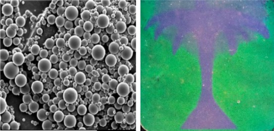
An easy approach to pattern angular-independent, multicolor reflective coatings based on cholesteric liquid-crystalline (CLC) particles is presented. CLC particles are fabricated by emulsification, which is a scalable, cost-effective, and environmentally friendly synthesis process. The photonic particles can be easily dispersed in a binder to produce reflective coatings. Furthermore, a simple strategy to remove the photonic cross-communication between the particles has been developed. By incorporating a reactive blue/green absorbing dye into the network structure of the CLC particles the cross-communication is absorbed by the dye, leading to well-defined structural colors. Moreover, we demonstrate the possibility of producing patterned multicolor images by controlled swelling of the particles by the binder.
Keywords: cholesteric liquid crystal, photonic particles, suspension polymerization, reflective coatings, structural color, photonic cross-communication
Introduction
In the field of optical materials, photonic crystals (PhCs) and polymers are typically used for applications such as optical sensors,1,2 displays,3,4 and reflective coatings.5−7 PhCs are used because they can modulate incident light with specific wavelengths to generate bright reflected structural colors. PhCs consist of one-, two-, or three-dimensional, periodic nanostructured materials, having alternating refractive indices. Self-assembled colloidal structures8 or spherical colloidal clusters9 are an example of PhCs that have bright structural colors because of their sub-micrometer three-dimensional organization.10 Despite the recent progress in PhCs,11 the assembling of such an ordered periodical structure involves in most cases complex and time-consuming steps. For instance, multistep lithographic techniques, which are often used in this regard, limit the final design and increase the cost. In contrast to PhCs, cholesteric liquid-crystalline (CLC) materials are soft photonic polymers that exhibit selective light reflection because of the presence of a helical molecular organization.12 The reflected wavelength depends on the pitch of the helical structure, which can be easily tuned by chemical composition, temperature, or other external stimuli,13,14 and can be stabilized by chemical cross-linking (i.e., by using acrylate-based liquid crystal monomers).15,16 The CLC alignment, which is crucial for proper reflection of light of a specific wavelength, requires the use of alignment layers. In addition, CLC-based reflective materials have a pseudo one-dimensional organization, leading to incident-angular-dependent reflection according to Bragg’s law. To this end, it remains a challenge to develop a facile method to prepare patterned multicolor photonic materials with angular-independent reflective properties.
To meet this challenge, three-dimensional organization of the helical structure by CLC polymer particles can be used to fabricate the angular-independent reflective materials.17−23 Such CLC particles can be easily processed and do not require alignment layers. Furthermore, they exhibit controlled expansion–contraction effects by solvent-swelling with large color-shifts.3,24 In a recent work, Beltran-Gracia and Parri.25 show a versatile approach to produce blue angular-independent reflective films based on CLC particles synthesized by suspension polymerization using organic solvents. In another research study, Lee et al.26 fabricated green reflective elastic films based on elastomeric reconfigurable CLC microcapsules. Nevertheless, the problem remains that the color of CLC particles-based coatings is, in most of the cases, influenced by the well-known photonic cross-communication phenomenon.27 This phenomenon occurs when off-normal incident light is reflected from one particle at a specific angle that can be reflected back to the observer by the neighboring particles, leading to multiple wavelengths reaching the observer.17,27,28 This is a clear disadvantage when green and red colors are intended, as blue light also reaches the observer. Because of this, patterned and/or full-color reflective coatings based on photonic CLC particles have not been reported to date.
In this work, we present a simple and effective method to fabricate angular-independent, patterned, reflective coatings based on photonic CLC particles. For the synthesis of the CLC particles, we used the suspension polymerization, because it is consistent and allows large-scale production of particles in water.25,29 To minimize photonic cross-communication between the CLC particles, we added a reactive blue/green absorbing dye to the CLC mixture. By using this cost-effective and environmentally friendly water-based emulsification process, we photopolymerized the CLC droplets into polymer particles. After the CLC particles were dispersed in a binder, we were able to fabricate reflective coatings with pure structural color reflection by simple coating techniques that do not require alignment layers. Moreover, we fabricated bicolor arbitrary patterns by controlled absorption of the binder.
Results and Discussion
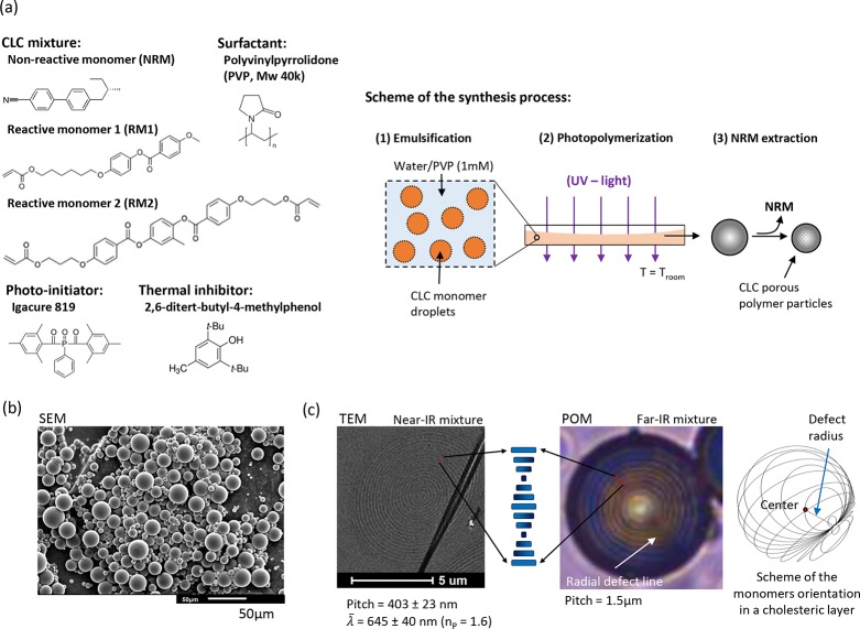
In order to synthesize the multicolor photonic particles, we used a CLC mixture containing reactive monomers (RM1 and RM2), a nonreactive monomer (NRM), a photoinitiator Irgacure 819, and a thermal inhibitor (2,6-ditert-butyl-4-methylphenol) (Figure 1a). The nomenclature and composition for all the formulations of the study are detailed in Table S1. We selected the NRM as the chiral dopant (HTP ≈ 7.230) because it helps to decrease the cholesteric temperature window to room temperature as can be deduced from the calorimetric analyses (Figure S1a). Furthermore, NRM acts as a porogen and by changing its concentration from 20 to 40%, the near-infrared reflection band shifts to the blue region of the visible spectrum as evidenced by the UV–vis–NIR spectra (Figure S1b). Finally, we chosen RM1 and RM2 reactive monomers to fix the CLC alignment and build up a cross-linked network with a glass transition temperature (Tg) of around 55 °C as deduced from the calorimetric analyses in Figure S2.
Figure 1.
Synthesis and characterization of the CLC particles: (a) compounds and scheme of the synthesis process, (b) SEM image of the particles and (c) TEM image of the cross section of a particle and POM image of a large-pitch particle including an illustration of the monomer’s orientation in the cholesteric layers.
We used suspension polymerization to synthesize the CLC particles, because it is a suitable method for large-scale production of particles. The method makes use of a water-based continuous phase with polyvinylpyrrolidone (PVP) as surfactant (Figure 1a). Monomer droplets were obtained after high-speed stirring for 15 min at T > Tiso and the cholesteric alignment was further induced on cooling down to room temperature (1 in Figure 1a). After photopolymerization (2 in Figure 1a) and further extraction of NRM (3 in Figure 1a), porous CLC polymer particles were obtained. The yield of particles was around 65%. In Figure S3, the IR spectra reveal the disappearance of the stretching vibration at 1630 cm–1 (stretching C=C), indicating that all acrylate groups have reacted. We confirmed the extraction of NRM by the disappearance of the C≡N stretching peak at 2260–2220 cm–1. The particles show a regular spherical shape with an average diameter of 15 ± 10 μm, measured by scanning electron microscopy (SEM) (Figure 1b). The cholesteric layers in the spherical particles follow a radial alignment as deduced from the existence of concentric circles in the transmission electron microscopy (TEM) image of the cross section of a particle in Figure 1c. In order to analyze the cholesteric layers under polarized optical microscopy (POM), we synthesized particles with a large-pitch of 1.5 μm by using the far-IR mixture (Figure 1c). The image confirms radial stacking of the cholesteric layers in concentric rings. Moreover, the presence of a radial defect line suggests that the alignment follows the well-known Frank-Pryce model. In this model, the orientation of the monomers in each cholesteric layer draws a family of circles corresponding to the intersection of all planes passing through the same point as illustrated in Figure 1c.31 This alignment is attributed to the use of PVP as surfactant, which reduces the energy at the water/droplet interface. Low interface energy favors planar alignment of the monomers and enables the growing of the helical structure toward the center.
In Figure 2, we show POM images of isolated particles dispersed in a refractive index matching matrix [poly(methylphenyl)siloxane, PMPS, refractive index ≈ 1.53]. The nomenclature of the particles is detailed in Table S1. The particles show the well-known Maltese cross when observed between crossed polarizers, which confirms the radial growing of the helical structure. Moreover, the presence of a defect line when observed without crossed polarizers confirms the Frank-Pryce model for the particles reflecting in the visible region of the spectrum (i.e., in the red particle). When observed in reflection mode a bright spot appears at the center of the particles. This is attributed to the Bragg reflection of the particles which is angular-independent for the observer. As stated in the introduction, only incident light reflected into the plane normal to the observer comes back to the observer as illustrated in Figure 2. In Figure 1c, we show the TEM image of the cross section of a red particle. The distance measured between three consecutive circles of the same tonality defines the helical pitch when the cut goes throughout the center of the particle. Then, on applying the relation λθ = n̅P cos θ, where θ is the viewing angle, n̅ is the average refractive index, and P is the pitch of the helical structure, the Bragg reflection, λ0°, can be calculated. When assuming a typical value of n® = 1.6 for LC particles, the calculated λ0° is around 645 nm, which matches with the observed red dot of the red particle. It must be noted that the Bragg reflection of the polymer particles is blue-shifted from the expected structural color according to the UV–vis spectra of the CLC mixtures (Figure S1b). This is explained by the inherent shrinkage of the particles caused by the extraction of NRM during the synthesis process (step 3, Figure 1a).
Figure 2.
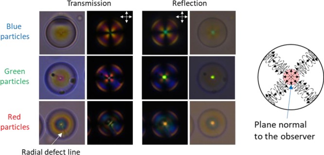
POM images of single blue, green, and red particles in PMPS as index matching immersion oil (n = 1.53) and a schematic picture of the alignment of the helical structure within the photonic particles.
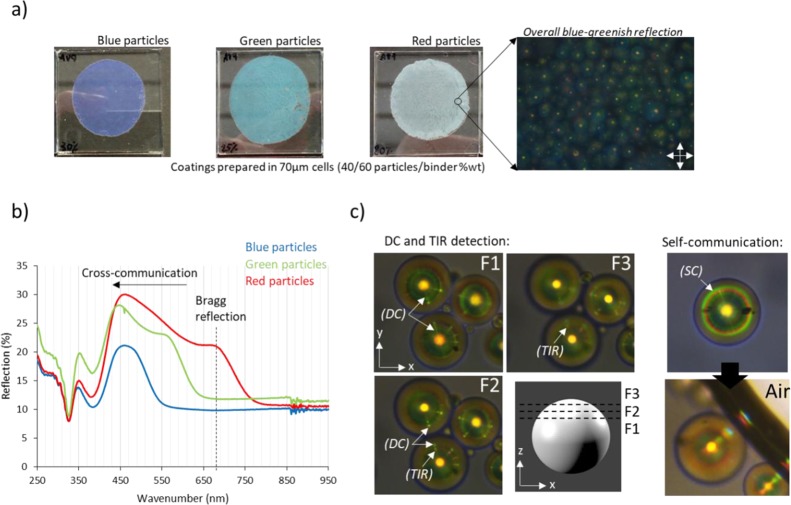
The preparation of the CLC particle-based reflective coatings requires a transparent, refractive index matching binder. We used a commercial high refractive index (n ≈ 1.57) photo-curable monomer, AgiSynDSM 2871. To fabricate thin coatings, we spread a dispersion of 40% in weight of polymer particles in the binder between glass plates. After photopolymerization of the binder, different coatings were obtained having blue, green, and red particles, respectively (Figure 3a). The coating made of blue particles clearly shows a dark blue color according to the particles’ Bragg reflection; in contrast, coatings made of green and red particles both deviate from their expected colors. The coating made of green particles has a light blue color, whereas the coating made of red particles is almost completely white. To better understand the deviation of the color observed with the color expected, we measured the UV–vis spectra of the coatings (Figure 3b). The coating made of blue particles shows a single reflection peak centered at 460 nm in agreement with the observed color. In contrast, coatings made of green and red particles show a double-peak reflection. The red-shifted peak is attributed to the Bragg reflection of the particles, because it matches with the observed colors in Figure 2, whereas the broader, blue-shifted peak is attributed to the photonic cross-communication. Photonic cross-communication takes place when incident light nonorthogonal to the cholesteric plane is reflected toward neighboring particles and these particles reflect it back to the observer. Total internal reflection (TIR) can also occur at the binder/air interface, leading to complex communication patterns. The broad peak associated with cross-communication extends to the UV region, explaining the whitish color for the “red” coating and the bluish color for the “green” coating. Note that cross-communication of blue particles is not visible to the naked eye because it is shifted to the UV region.
Figure 3.
(a) Pictures of 70 μm coatings made with blue, green, and red particles, respectively, including the POM image of the red coating, (b) UV–vis spectra of the coatings (dashed line indicates the reflection band of the red particles), and (c) photonic cross-communication between particle arrays.
To further understand the cross-communication phenomenon, we have analyzed a thin film of near-IR particles (λ0° = 796 nm) dispersed in the refractive index matching siloxane, PMPS, under the optical microscope (Figure 3c). Close to the center of the particles (F1), we can observe direct-communication (DC) as multiple green rays pointing toward neighboring particles. On focusing toward the top of the particle (F2–F3), DC rays vanish and green-reddish bright dots appear closer to the center of the particle in the x–y plane. This is caused by TIR of the light reflected from one particle to the PMPS/air interface and reflected back to the observer by neighboring particles. In general, we observe green DC rays and red TIR dots, suggesting that DC takes place around 45° (λ45° = 689 nm) and TIR around 30° (λ30° = 562 nm) regardless of the particle size (a detailed explanation is provided in the Supporting Information, Figure S4). Finally, we observe two concentric green and red reflection rings appearing at a certain distance from the center of most of the particles. This can be related to self-communication (SC) with the air interface, which occurs when the light is self-reflected from the PMPS/air interface to the particle and reflected back to the observer, as depicted in Figure S4b. As can be seen, SC leads to bright blue, green, and red reflection, which explains the strong communication peaks observed in the UV–vis spectra and the blue-greenish reflection surrounding the particles in the POM image of Figure 3a.
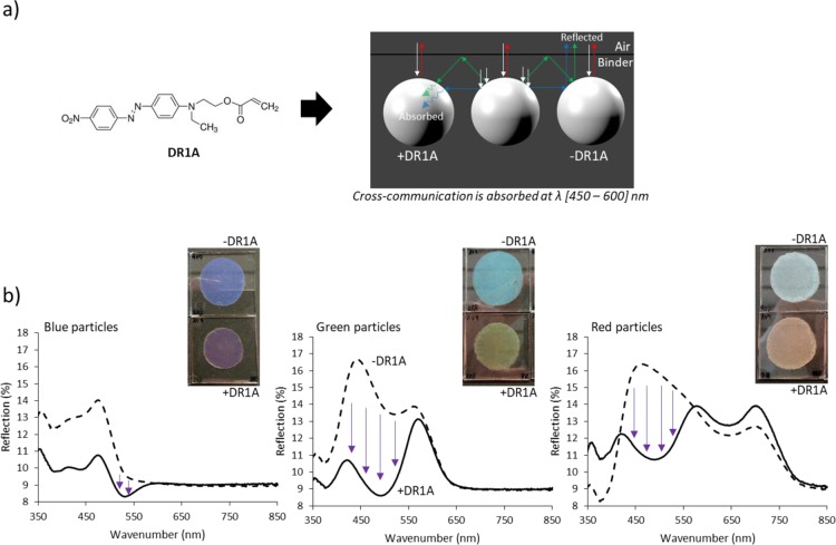
In order to minimize the effect of the photonic cross-communication, we added a small amount (0.1% in weight) of a reactive dye (DR1A) to the CLC mixtures before the suspension polymerization (Figure 1a). The dye has an absorption peak between 450 and 600 nm (Figure S5) and, therefore, is expected to absorb cross-communicating rays (Figure 4a). Coatings made of red, green, and blue DR1A-photonic particles were prepared as described before and the UV–vis spectra were measured (Figure 4b). The coating made of green DR1A particles shows clearly a green-yellowish color and the coating made of red DR1A particles has a reddish color according to the Bragg reflection wavelength. Both spectra reveal a strong decrease in the reflection band at the absorption region of the dye, suggesting that the dye is effectively absorbing the blue and green cross-communication. Note that the use of 0.1% in weight of DR1A is enough to minimize the cross-communication while maintaining 80% transmission in the absorption region of the dye (Figure S5). It must be noted that the use of DR1A for blue reflective coatings is not appropriate as the dye absorbs in the green region and therefore the blue turns into purple as it is observed. Regardless, the blue reflective coatings do not show cross-communication in the visible region; hence, the dye is not required to achieve proper coloration.
Figure 4.
(a) Scheme of the photonic cross-communication absorption mechanism by adding a blue/green-absorbing dye acrylate (DR1A) to the polymer particles and (b) photographs of 70 μm coatings made of red, green, and blue particles with and without DR1A and the corresponding UV–vis spectra.
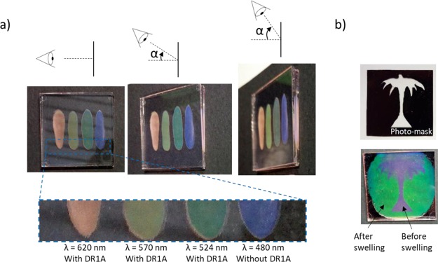
By using different structural colored particles containing DR1A, we were able to fabricate reflective coatings that exhibit angular-independent structural colors when observed by the naked eye (Figure 5a). Additionally, we show the possibility of tuning the reflected color from the same batch of particles by altering the absorption of the binder. Swelling of the particles leads to an increase of the pitch and, therefore, a red shift of the reflected color. This can be used to prepare patterned images (Figure 5b). We fabricated a patterned bicolored, purple and green, image by using blue DR1A particles. First, we spread a dispersion of 40% in weight of polymer particles in the binder between glass plates. Then, we placed a photomask patterned with the tree model on top of the sandwich and the visible region was exposed to UV light. In the exposed region the binder was polymerized and the particles were immobilized. Afterwards, we raised up the temperature above the Tg of the particles (Tg ≈ 55 °C) and a red shift was observed in the unexposed regions, demonstrating the absorption of the unreacted acrylates by the flexible porous particles. We carried out a second UV-curing process on the entire sample and the result reveals a bicolor image with defined contours. In certain areas, both left and right sides, and around the tree crown, a bluish color is observed instead of green. This is attributed to an insufficient amount of binder to achieve the maximum swelling of the particles. During the heating process, the viscosity of the binder decreases and therefore uncontrolled flow driven by thickness irregularities in between the glass plates may take place. It is worth noting that by decreasing the cross-linking density of the particles, that is decreasing the RM1 to RM2 relation (Figure 1a), we expect an enhancement of the swelling capabilities because of an increased flexibility of the network structure and therefore a larger color change, for instance, from blue to red.
Figure 5.
(a) Blue, green, yellowish, and red coatings shown at different angles (top) and zoom in of the coatings (bottom) and (b) bicolor patterned reflective coating made by using blue DR1A particles and a photomask.
Conclusions
An easy and effective approach for the preparation of angular-independent full-color reflective coatings based on CLC particles is shown. The particles are synthesized following a scalable, cost-effective, and environmentally friendly process. The optical properties of the particles are easily controlled by the amount of chiral dopant in the CLC mixture. Particles from UV to IR reflection can be synthesized and easily dispersed in a binder to further prepare reflective coatings by simple coating techniques. The optical properties of the coatings have been extensively discussed including relevant insights into the photonic cross-communication phenomenon between particles and the surrounding medium. It has been suggested that not only DC or TIR can reach the observer, but also SC of the particles with the binder/air interface results in additional light reaching the observer. Thanks to the addition of a reactive blue/green-absorbing dye the green and blue photonic-communication is absorbed, allowing the preparation of reflective coatings with reflections ranging from blue to red with accurate control on the final color. In addition, a bicolor patterned image has been prepared from a single batch of particles owing to the swelling properties of the porous structure above the glass transition temperature.
Experimental Section
Synthesis of CLC Particles
The CLC particles were synthesized by suspension polymerization (see scheme in Figure 1a). The monomer mixture consists of reactive monomers RM1 (monoacrylate), RM2 (cross-linker diacrylate), and a nonreactive chiral dopant NRM, all of them purchased from Merck. Photoinitiator Irgacure 819 (1% wt) was purchased from CIBA Inc. and the thermal inhibitor (2,6-ditert-butyl-4-methylphenol, BHT, 0.5% wt) was purchased from Sigma-Aldrich. All compounds were used without any further purification. The aqueous phase was formed by dissolving PVP (Mw = 40k, Sigma-Aldrich) in deionized water (1 mM). The synthesis was carried out in three steps: the formation of the CLC droplets (emulsification), the polymerization, and the extraction of the NRM. For the emulsification, the monomers’ mixture, photoinitiator, and thermal inhibitor were first dissolved in dichloromethane and sonicated for 3 min. Then, the solvent was flushed with air and completely evaporated by raising the temperature up to 80 °C for 10 min. Afterwards, the preheated aqueous phase at 80 °C was poured on the melted monomers and the droplets were formed and stabilized by stirring with an IKA Werke (Ultra-Turrax T8) at 15 000 rpm for 15 min. Finally, the cholesteric alignment was induced by slowly cooling down the emulsion to room temperature. For the polymerization, the emulsion was poured in a thin glass container placed inside a nitrogen box with continuous magnetic stirring (300 rpm). The polymerization was triggered by shining UV light at maximum intensity with a mercury lamp (EXFO OmniCure S2000, λ = 350–450 nm) for 30 min to ensure full conversion of the acrylate groups. Note that the thin glass container helps the UV light to cross throughout the sample. Once the polymerization is over, the particles were washed first with ethanol to remove the surfactant and then twice with tetrahydrofuran to extract the NRM.
Preparation of the Coatings
Particles-based coatings were prepared by dispersing the particles in a commercial photocurable monomer, AgiSynDSM 2871 (O-phenylphenoxyethyl acrylate mixture), with the refractive index matching the refractive index of the particles (n = 1.571) and transparency in the visible region. One drop of the dispersion was poured on the center of a clean glass plate and four small droplets of a dispersion of 70 μm particles in the photocurable resin were added to the corners of the plate as spacers. Then, a second clean glass plate was carefully placed on top and slightly compressed following regular circular movements until the 70 μm particles are in contact with both glass plates. Finally, the cell was exposed to UV light for 5 min in order to polymerize the acrylates. The coatings were left in between the glass plates for the further measurements.
Characterization Methods
Thermal transitions of the liquid-crystalline mixtures and the particles were analyzed by differential scanning calorimetry (DSC) using a TA Instruments Q2000 calorimeter with constant heating and cooling rates of 10 °C/min. Optical images of the cholesteric phases were taken by POM using a microscope (Leica DM2700M) equipped with a Leica MC170 HD high-resolution camera in reflection mode under crossed polarizers. The conversion of the acrylate groups and the extraction of the NRM were studied by infrared spectroscopy using a Varian 670 IR spectrometer equipped with a microscopy setup over a range of 4000–650 cm–1. POM images of the particles were taken in reflection and transmission modes either under crossed polarizers or without. The particles’ size population was analyzed by SEM using a JEOL SEM JSM-IT100: the particles were dispersed in sticky conductive film and sputter-coated with a gold target at 60 mA over 30 s. The internal configuration of the cholesteric layers was analyzed by TEM of the particles’ cross section using a Tecnai 20 (type Sphera) by FEI operating with a LaB6 filament at 200 kV under slight under-focus conditions. The particles were embedded in an EpoFix epoxy media. Cross sections were cut at room temperature using an ultra-microtome (Reichert-Jung Ultracut E) with a 60 nm setting thickness. The obtained cross sections were transferred to a carbon film-covered grid (Electron Microscopy Sciences, CF200-CU). The reflection of the CLC mixtures and particles-based coatings was measured through ultraviolet–visible spectroscopy (UV–vis) by using a PerkinElmer LAMBDA 750 with a 150 mm integrating sphere over a range of 250–1000 nm (wavelength) at room temperature.
Acknowledgments
This work was financially supported by the Netherlands Organization for Scientific Research (TOP-PUNT 718.016.003). The authors thank Audrey Debije-Popson and Michael Debije for valuable comments on the paper.
Supporting Information Available
The Supporting Information is available free of charge on the ACS Publications website at DOI: 10.1021/acsami.9b02680.
Composition of the CLC mixtures; DSC curves, UV–vis, and FTIR spectra of the CLC mixtures and particles; photonic cross-communication pictures and explanation; and transmission spectra of the DR1A dissolved in the binder (PDF)
The authors declare no competing financial interest.
Supplementary Material
References
- Mulder D. J.; Schenning A. P. H. J.; Bastiaansen C. W. M. Chiral-Nematic Liquid Crystals as One Dimensional Photonic Materials in Optical Sensors. J. Mater. Chem. C 2014, 2, 6695–6705. 10.1039/c4tc00785a. [DOI] [Google Scholar]
- Davies D. J. D.; Vaccaro A. R.; Morris S. M.; Herzer N.; Schenning A. P. H. J.; Bastiaansen C. W. M. A Printable Optical Time-Temperature Integrator Based on Shape Memory in a Chiral Nematic Polymer Network. Adv. Funct. Mater. 2013, 23, 2723–2727. 10.1002/adfm.201202774. [DOI] [Google Scholar]
- Ha N. Y.; Ohtsuka Y.; Jeong S. M.; Nishimura S.; Suzaki G.; Takanishi Y.; Ishikawa K.; Takezoe H. Fabrication of a Simultaneous Red-Green-Blue Reflector Using Single-Pitched Cholesteric Liquid Crystals. Nat. Mater. 2008, 7, 43–47. 10.1038/nmat2045. [DOI] [PubMed] [Google Scholar]
- Arsenault A. C.; Puzzo D. P.; Manners I.; Ozin G. A. Photonic-Crystal Full-Colour Displays. Nat. Photonics 2007, 1, 468–472. 10.1038/nphoton.2007.140. [DOI] [Google Scholar]
- Khandelwal H.; Schenning A. P. H. J.; Debije M. G. Infrared Regulating Smart Window Based on Organic Materials. Adv. Energy Mater. 2017, 7, 1602209. 10.1002/aenm.201602209. [DOI] [Google Scholar]
- Moirangthem M.; Schenning A. P. H. J. Full Color Camouflage in a Printable Photonic Blue-Colored Polymer. ACS Appl. Mater. Interfaces 2018, 10, 4168–4172. 10.1021/acsami.7b17892. [DOI] [PMC free article] [PubMed] [Google Scholar]
- van Heeswijk E. P. A.; Kloos J. J. H.; Heer J. d.; Hoeks T.; Grossiord N.; Schenning A. P. H. J. Well-Adhering, Easily Producible Photonic Reflective Coatings for Plastic Substrates. ACS Appl. Mater. Interfaces 2018, 10, 30008–30013. 10.1021/acsami.8b11583. [DOI] [PMC free article] [PubMed] [Google Scholar]
- Lee I.; Kim D.; Kal J.; Baek H.; Kwak D.; Go D.; Kim E.; Kang C.; Chung J.; Jang Y.; et al. Quasi-Amorphous Colloidal Structures for Electrically Tunable Full-Color Photonic Pixels with Angle-Independency. Adv. Mater. 2010, 22, 4973–4977. 10.1002/adma.201001954. [DOI] [PubMed] [Google Scholar]
- Gu H.; Zhao Y.; Cheng Y.; Xie Z.; Rong F.; Li J.; Wang B.; Fu D.; Gu Z. Tailoring Colloidal Photonic Crystals with Wide Viewing Angles. Small 2013, 9, 2266–2271. 10.1002/smll.201203179. [DOI] [PubMed] [Google Scholar]
- Lova P.; Manfredi G.; Comoretto D. Advances in Functional Solution Processed Planar 1D Photonic Crystals. Adv. Opt. Mater. 2018, 6, 1800730. 10.1002/adom.201800730. [DOI] [Google Scholar]
- Ko Y.-L.; Tsai H.-P.; Lin K.-Y.; Chen Y.-C.; Yang H. Reusable Macroporous Photonic Crystal-Based Ethanol Vapor Detectors by Doctor Blade Coating. J. Colloid Interface Sci. 2017, 487, 360–369. 10.1016/j.jcis.2016.10.061. [DOI] [PubMed] [Google Scholar]
- White T. J.; McConney M. E.; Bunning T. J. Dynamic Color in Stimuli-Responsive Cholesteric Liquid Crystals. J. Mater. Chem. 2010, 20, 9832–9847. 10.1039/c0jm00843e. [DOI] [Google Scholar]
- Braun L. B.; Hessberger T.; Zentel R. Microfluidic Synthesis of Micrometer-Sized Photoresponsive Actuators Based on Liquid Crystalline Elastomers. J. Mater. Chem. C 2016, 4, 8670–8678. 10.1039/c6tc02587k. [DOI] [Google Scholar]
- Li Q.Intelligent Stimuli-Responsive Materials: From Well-Defined Nanostructures to Applications; Li Q., Ed.; John Wiley & Sons, Inc.: Hoboken, NJ, 2013. [Google Scholar]
- Mitov M. Cholesteric Liquid Crystals with a Broad Light Reflection Band. Adv. Mater. 2012, 24, 6260–6276. 10.1002/adma.201202913. [DOI] [PubMed] [Google Scholar]
- Cross-Linked Liquid Crystalline Systems; Broer D. J., Crawford G. P., Zumer S., Eds.; CRC Press: Boca Raton, FL, 2011. [Google Scholar]
- Geng Y.; Noh J.; Drevensek-Olenik I.; Rupp R.; Lenzini G.; Lagerwall J. P. F. High-Fidelity Spherical Cholesteric Liquid Crystal Bragg Reflectors Generating Unclonable Patterns for Secure Authentication. Sci. Rep. 2016, 6, 26840. 10.1038/srep26840. [DOI] [PMC free article] [PubMed] [Google Scholar]
- Li Y.; Jun-Yan Suen J.; Prince E.; Larin E. M.; Klinkova A.; Thérien-Aubin H.; Zhu S.; Yang B.; Helmy A. S.; Lavrentovich O. D.; et al. Colloidal Cholesteric Liquid Crystal in Spherical Confinement. Nat. Commun. 2016, 7, 12520. 10.1038/ncomms12520. [DOI] [PMC free article] [PubMed] [Google Scholar]
- Kim J.-G.; Park S.-Y. Photonic Spring-Like Shell Templated from Cholesteric Liquid Crystal Prepared by Microfluidics. Adv. Opt. Mater. 2017, 5, 1700243. 10.1002/adom.201700243. [DOI] [Google Scholar]
- Lopez-Leon T.; Fernandez-Nieves A. Drops and Shells of Liquid Crystal. Colloid Polym. Sci. 2011, 289, 345–359. 10.1007/s00396-010-2367-7. [DOI] [Google Scholar]
- Chen L.; Li Y.; Fan J.; Bisoyi H. K.; Weitz D. A.; Li Q. Photoresponsive Monodisperse Cholesteric Liquid Crystalline Microshells for Tunable Omnidirectional Lasing Enabled by a Visible Light-Driven Chiral Molecular Switch. Adv. Opt. Mater. 2014, 2, 845–848. 10.1002/adom.201400166. [DOI] [Google Scholar]
- Fan J.; Li Y.; Bisoyi H. K.; Zola R. S.; Yang D.-k.; Bunning T. J.; Weitz D. A.; Li Q. Light-directing omnidirectional circularly polarized reflection from liquid-crystal droplets. Angew. Chem., Int. Ed. 2015, 54, 2160–2164. 10.1002/anie.201410788. [DOI] [PubMed] [Google Scholar]
- Wang L.; Chen D.; Gutierrez-Cuevas K. G.; Krishna Bisoyi H.; Fan J.; Zola R. S.; Li G.; Urbas A. M.; Bunning T. J.; Weitz D. A.; et al. Optically Reconfigurable Chiral Microspheres of Self-Organized Helical Superstructures with Handedness Inversion. Mater. Horiz. 2017, 4, 1190–1195. 10.1039/c7mh00644f. [DOI] [PMC free article] [PubMed] [Google Scholar]
- Stumpel J. E.; Broer D. J.; Schenning A. P. H. J. Stimuli-Responsive Photonic Polymer Coatings. Chem. Commun. 2014, 50, 15839–15848. 10.1039/c4cc05072j. [DOI] [PubMed] [Google Scholar]
- Beltran-Gracia E.; Parri O. L. A New Twist on Cholesteric Films by Using Reactive Mesogen Particles. J. Mater. Chem. C 2015, 3, 11335–11340. 10.1039/c5tc02920a. [DOI] [Google Scholar]
- Lee S. S.; Kim S. K.; Won J. C.; Kim Y. H.; Kim S.-H. Reconfigurable Photonic Capsules Containing Cholesteric Liquid Crystals with Planar Alignment. Angew. Chem., Int. Ed. 2015, 54, 15266–15270. 10.1002/anie.201507723. [DOI] [PubMed] [Google Scholar]
- Noh J.; Liang H.-L.; Drevensek-Olenik I.; Lagerwall J. P. F. Tuneable Multicoloured Patterns from Photonic Cross-Communication between Cholesteric Liquid Crystal Droplets. J. Mater. Chem. C 2014, 2, 806–810. 10.1039/c3tc32055c. [DOI] [Google Scholar]
- Aßhoff S. J.; Sukas S.; Yamaguchi T.; Hommersom C. A.; Le Gac S.; Katsonis N. Superstructures of Chiral Nematic Microspheres as All-Optical Switchable Distributors of Light. Sci. Rep. 2015, 5, 14183. 10.1038/srep14183. [DOI] [PMC free article] [PubMed] [Google Scholar]
- Wang X.; Bukusoglu E.; Abbott N. L. A Practical Guide to the Preparation of Liquid Crystal-Templated Microparticles. Chem. Mater. 2017, 29, 53–61. 10.1021/acs.chemmater.6b02668. [DOI] [Google Scholar]
- Ko S.-W.; Huang S.-H.; Fuh A. Y.-G.; Lin T.-H. Measurement of Helical Twisting Power Based on Axially Symmetrical Photo-Aligned Dye-Doped Liquid Crystal Film. Opt. Express 2009, 17, 15926. 10.1364/oe.17.015926. [DOI] [PubMed] [Google Scholar]
- Bouligand Y.; Livolant F. The Organization of Cholesteric Spherulites. J. Phys. 1984, 45, 1899–1923. 10.1051/jphys:0198400450120189900. [DOI] [Google Scholar]
Associated Data
This section collects any data citations, data availability statements, or supplementary materials included in this article.


