Abstract
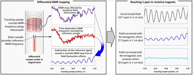
Powered resistive and resistive-superconductive hybrid magnets can reach fields higher than superconducting NMR magnets but lack the field homogeneity and temporal stability needed for high resolution NMR. Due to field fluctuations in powered magnets, commercially available mapping systems fail to produce maps of these magnets with sufficient reproducibility, thus hampering attempts to improve homogeneity of the field they generate. Starting with a commercial mapper, we built a mapping system which uses a two-channel (measurement + reference) mapper probe. We used this system to map and then to shim two magnets of Florida Bitter type at the National High Magnetic Field Laboratory in Tallahassee, FL. With a combination of passive (ferromagnetic) and active shims we achieved 2.3 ppm homogeneity in 1 cm diameter spherical volume (dsv) at 25.0 T in the Keck resistive magnet, and 0.9 ppm homogeneity in 1 cm dsv at 23.5, 28.2, and 35.2 T in the series-connected resistive-superconductive hybrid (SCH) magnet.
Keywords: nuclear magnetic resonance (NMR), electromagnets, resistive magnets, superconductive magnets, hybrid magnets, series-connected hybrid (SCH), homogeneity, shimming, field fluctuations, high fields, 1.5 GHz, 1500 MHz, 1000 MHz, 25 T, 35.2 T, 36 T
Graphical Abstract
Introduction
In areas such as high-resolution NMR where high magnetic field homogeneity is critical, homogeneity of an as-built magnet rarely satisfies the end user. Before the magnet is put to service, the field is corrected using electric currents and/or pieces of magnetic materials. The art of magnet shimming dates back to the early days of NMR itself [1].
A systematic approach to shimming starts with a field map, often expanded in a series of spherical harmonics [2]. In a typical NMR mapper a single NMR sample is advanced step-wise along a certain trajectory, and the resonance frequency of the NMR sample is recorded at each stop. The trajectory can be helical [3] or helispherical [4]; some mappers use a 3-dimesional grid of points [5]. Variants of this method include multiplexed systems where several samples are positioned on a circle [6] which moves axially, or a semicircle [7] or an arm [8] which makes a radial sweep. Using such arrays reduces the number of stops on the trajectory and shortens acquisition time. Since the field of persistent superconducting NMR magnets is virtually time-independent, such sequential or parallel-sequential acquisition does not introduce significant errors. In comparison, water-cooled DC-powered magnets produce relatively large temporal magnetic field fluctuations from noise in the power supply and changes in the temperature and rate of the magnet cooling water [9]. Unless special arrangements are made, the amplitude of these fluctuations sets the floor to mapping precision: when fluctuations exceed the spatial field distribution across the volume of interest, sequentially-acquired map data gets buried under variations in the NMR Larmor frequency.
Most modern high-resolution NMR spectrometers use persistent superconducting magnets. However, there are no such magnets capable of producing more than 23.5 T, while powered resistive magnets and resistive-superconductive hybrid magnets routinely achieve sustained fields up to 45 T [10]. Although powered resistive magnets can reach extremely high fields, they have not typically been designed to achieve field homogeneity better than about 1 part per thousand. Consequently, until recently routine use of ultra-high field powered magnets for NMR spectroscopy was limited primarily to ultra-wide line experiments [11,12] due to both insufficient homogeneity and strong temporal fluctuations of the magnetic field. NMR spectroscopy at ultra-high magnetic field promises increased sensitivity and resolution, especially for half-integer quadrupolar isotopes [13–15], and is expected to provide new insights into the structure of materials and biological samples. For that purpose it is important to improve the homogeneity and stability of fields in powered magnets.
Several reports on high-resolution NMR in resistive magnets focus on innovative techniques to circumvent shortcomings of these systems. Sigmund proposed using a conductive cylindrical shield to reduce the decoherence effect of fluctuating fields [16,17]. Li proposed using feedback control based on an inductive sensor to reduce high frequency fluctuations [18]. Additionally, several investigators introduced experimental techniques to minimize the effect of field fluctuations and inhomogeneity [19,20]. In a pioneering project, Van Bentum and co-workers addressed both the spatial and temporal limitations of a 24 T Bitter-type magnet [15]. They carried out field mapping first by a rapidly moving inductive sensor to determine the axial inhomogeneity, then cancelled the Z2 and Z4 terms with a ferromagnetic cylinder. They then carried out a helical NMR field map to determine other low order inhomogeneity. A two-stage system based on inductive sensors and an integrating preamplifier was used to correct for drift and noise during the map. Small amounts of material were removed from the ferromagnetic cylinder to correct for radial inhomogeneity. As will be the case in our study, ultimate homogeneity was limited by the reproducibility of the position of the Bitter coils during magnet maintenance. Similar issues with field stability have been encountered with low-field electromagnets used for MRI. A stationary reference NMR channel as a part of a multiplexed NMR mapper probe was successfully used to shim a 0.15 T water-cooled resistive whole body imaging magnet [8].
A number of Bitter-type powered resistive magnets with improved homogeneity have been built at the NHMFL to be used for high demanding applications such as magnetic resonance. The series-connected hybrid (SCH) magnet with superconducting outsert and Florida-Bitter type resistive insert reached 36.1 T field in November 2016 [21,22]. Prior to the completion of the SCH magnet, NHMFL users could choose between two resistive magnets with higher field uniformity than a standard high field magnet. The 25-tesla, 52 mm bore all-resistive magnet funded by the W.M. Keck Foundation (Keck magnet) was completed in 2000 [23] and was the first magnet to produce high resolution 1H spectra above 1.0 GHz [19]. The other magnet generated up to 29 T in a 32 mm bore [24,25]. In the current project we used passive and active field correction elements to further improve the fields of the SCH and Keck magnets, while the 29 T magnet did not provide enough room for such correction. Recently, the Keck magnet was used as a test bed for developing technologies necessary for NMR on the SCH magnet. Both resistive magnets were decommissioned shortly after the SCH magnet reached its target field.
In this paper we report using a differential mapping technique based on reference mapper hardware for successful acquisition of NMR maps in the Keck and SCH powered magnets at the NHMFL, and convergence of the two magnets with a combination of passive and active shims to 2.3 and 0.9 ppm respectively. In order to improve the precision of maps beyond the field fluctuation limit of powered magnets we added a stationary (fixed) reference channel to a commercial mapper probe connected to the second receiver of the spectrometer. This channel provides simultaneous measurement of the time-dependent background field for each point of the sequentially acquired map. The homogeneity achieved is sufficient for a broad range of experiments in solid state NMR and NMR of quadrupolar nuclei. This result is also a significant improvement over 20 ppm [15], 12 ppm [23], and 5.6 ppm [26] reported previously for shimming Bitter-type resistive magnets. With this work we complete the two-decades-long challenge [23,27] to reach 1 ppm field homogeneity above 24 T.
Instrumentation
Shim systems
Unlike persistent superconducting NMR magnets, the Keck and SCH were constructed without superconducting shim coils. Consequently, it was necessary to provide each magnet with both coarse and fine field corrections. After evaluating an approach of high-current water-cooled active shims within the housing of the resistive coil [28], we selected a combination of ferromagnetic inserts [2] for rough field correction, with active shims coils carrying 0.5-1 A for fine-tuning the field homogeneity. Combining active and passive shims has been successfully used before for “unshimmable” magnets [29–31]. Given the space constraints and the necessity to remove heat dissipated by resistive shim coils, we could correct only a small number of terms. Our resistive shim set corrects 1st order terms (Z, X, Y), a second-order axial term (Z2), and second order radial terms (ZX, ZY), while the passive shim set corrects Z, Z2, Z3, X and Y.
Unlike superconducting magnets for which ramp time can be days or even weeks, the SCH magnet ramps up to maximum field in about a half-hour [21]. For resistive magnets like the Keck, ramp time is typically several minutes. Short ramp times make it practical to conduct NMR experiments at different field strengths. However, for a resistive magnet the field profile of the magnet changes with the magnetic field strength. In addition to changing the background field of the magnet, the value of magnet current also affects temperature profile within the resistive coils. This causes a substantial dissimilarity between field profiles and calls for a separate set of passive shims for each operating field.
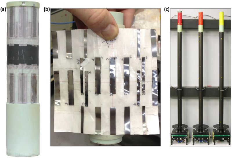
For this project we generated a set of passive shims for the Keck magnet operating at 25.0 T (1.06 GHz), and three sets for the SCH magnet operating at 23.5, 28.2 and 35.2 T, corresponding to 1.0, 1.2, and 1.5 GHz operating frequencies of the NMR spectrometer console dedicated to this system. Rather than mounting the passive shims to the magnet bore tube [23] or the resistive shim tube, we incorporated them into the probe covers as shown in Figure 1. This arrangement makes it easy to reconfigure experimental setup for a different magnetic field strength, which only involves retuning the probe and changing the probe cover. Since powered magnets are not energized when the NMR probes are inserted or removed, ferromagnetic shims on the probe covers do not pull into the magnets.
Figure 1.
Passive shims: (a) – SCH passive shim set mounted onto SCH NMR probe cover (42 mm OD) machined from FR4 fiberglass. The middle of the trough is aligned with the center of field of the magnet and with the NMR sample. Iron foil pattern families (axial, radial) attached to translucent paper are mounted in layers. The black tape visible in the middle helps to hold the patterns to the probe cover. Iron pieces (vertical rectangles for X shim, horizontal rings for axial shim) appear grey. Photo taken before wrapping with final protective tape coat. (b) – Keck ZX shim ready to be mounted on the Keck NMR probe cover. (c) – NMR probes for the SCH magnet with interchangeable color-coded probe caps, 35.2 T (red), 28.2 T (orange), and 23.5 T (yellow).
Passive shims for the SCH and Keck magnets were constructed in layers that correct axial terms, first order radial terms, and second order radial terms (if present). Paper sheets with attached iron or low-carbon steel foil cutouts were wrapped around the G10 probe cover and secured with tape (Figure 1a, b). A trough cut into the cover on a lathe (SCH) or formed by glued-on rings (Keck) aligns the wraps with respect to the center of field of the magnet and protects them from rubbing against the magnet bore. The final protective tape coat is color-coded to distinguish between shim sets designed for different field strengths (Figure 1c).
Setup for differential NMR mapping
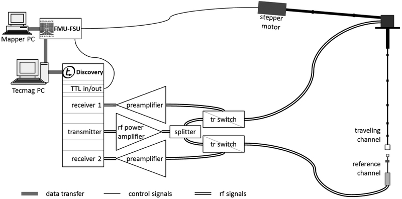
The mapper system consists of a combination of commercial and home-built hardware. NMR acquisition for the traveling and reference channels of the mapper probe was performed using aTecmag Discovery console (Tecmag, Inc., Houston TX) running NTNMR software. Probe motion was controlled by a factory customized Field Mapping Unit (FMU) from RRI (Resonance Research, Inc., Billerica, MA). We added TTL triggers to the one-pulse NMR sequence for synchronization between NMR acquisition and probe trajectory stops. Recently we updated the system to a Tecmag Redstone console running TNMR software, and replaced two host computers with one which communicates with both the NMR spectrometer and the mapper controller. However, the data reported here were acquired with the Discovery system.
The console was configured in a single transmitter/dual receiver mode. In this mode, a single rf pulse from the amplifier is relayed to both probe channels through a power splitter and two home-built t/r switches. Signals from the two samples are acquired by two receivers simultaneously and independently in order to cancel both low and high frequency fluctuations of the background field.
Acquisition and processing tasks are shared between two pieces of software running on two computers. The proprietary RRI Unifier software which runs on the Mapper PC sets up mapping parameters such as trajectory length, step size, and number of points. The latter parameter is transferred to the Tecmag PC. A VBScript application (Microsoft Visual Basic Scripting Edition, Microsoft, Redmond, WA) running on the Tecmag PC updates parameters in a NTNMR pulse sequence and starts the pulse sequence execution. The mapper host computer (Mapper PC) and spectrometer host computer (Tecmag PC) communicate through the Kermit protocol (www.kermitproject.org) with the FMU.
After the acquisition is complete, the script uses NTNMR commands to sort data points from the two receivers, and to process the FIDs. Processing includes zero-fill, exponential multiplication (1-4 kHz, depending on the level of field inhomogeneity), and Fourier transform. The script then searches for maximum magnitude point (the peak position) in each spectrum. For each pair of spectra (traveling, reference), the script records the difference between peak positions into a text file which is then transferred to the Mapper PC. From this data, the RRI Unifier software generates a field map and expands the magnetic field inhomogeneity in spherical harmonics.
Mapper probe with external reference channel
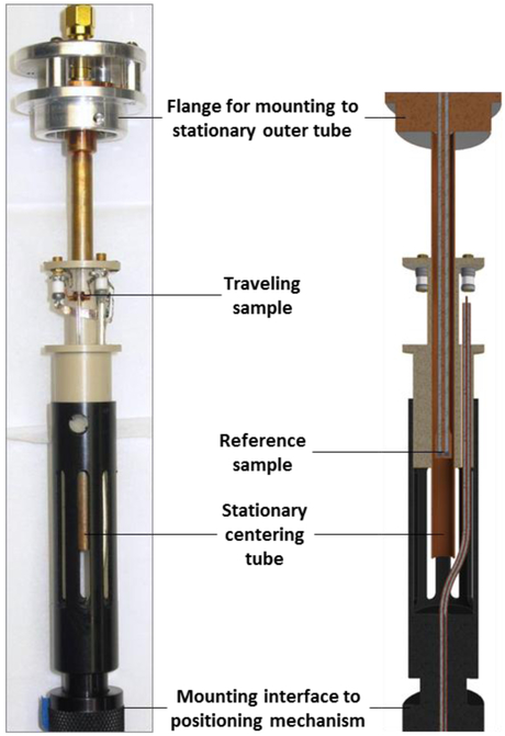
We developed a mapper probe based on the RRI field mapping system and included an additional reference sample which remains at the center of the magnet while the mapping sample traces a helical path around it. Our NMR mapper probe (Figure 3) has two isolated rf channels tuned to the same frequency and filled with the same or similar sample solution. The probe head of the traveling channel (Figure 4a) has its sample coil positioned 5 mm off-axis of the magnet. Good control over sample location is necessary in order to generate correct field maps. We use a 0.8 mm OD capillary as a sample tube and limit the length occupied by the solution to 1 mm so that the measurement of the magnetic field is localized. A wax seal positions the sample in the rf coil window.
Figure 3.
Traveling channel and reference channel of the mapper probe - photo and cutaway rendering. The reference channel is mounted to the outer tube (not shown) via a flange. A copper centering tube improves axial alignment of the traveling channel and protects the reference channel from mechanical and rf interference. The traveling channel is attached to a torque converter through several extensions of calibrated length.
Figure 4.
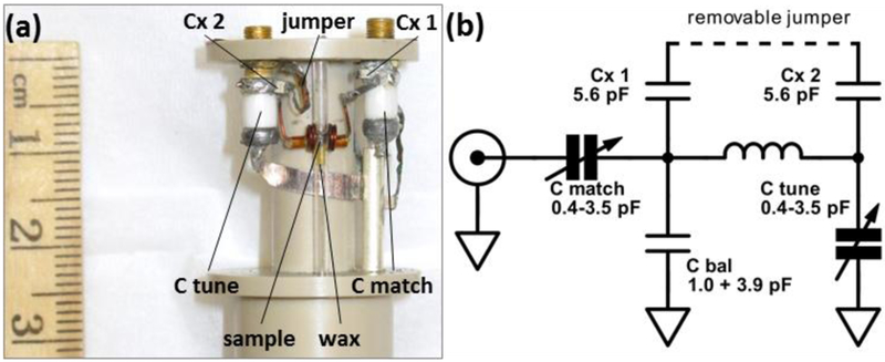
Traveling channel of the mapping probe: (a) – photo, (b) – circuit diagram. Aqueous LiCl NMR sample is restricted to 1 mm length in 0.8 ID glass capillary using wax. RF matching circuit with Helmholtz sample coil tunes to 460-700 MHz. Range can be quickly extended down to ~350 MHz by soldering a jumper between two Cx capacitors.
A vertical orientation of the capillary makes it easier to guarantee the correct radial offset of the sample but requires a transverse rf sample coil, of which a Helmholtz coil is probably easiest to make. The matching network for the sample coil (Figure 4b) can tune from about 350 to 700 MHz. We use a removable jumper to reach the lower portion of the tuning range. The probe head is attached to a torque converter (“drive screw”) to drive the NMR sample on a helical path with a 2.5 mm pitch [3]. The probe circuit is connected to the NMR console through interchangeable extensions with coaxial RF interconnects. The head has a 0.25 inch hole along its axis to allow it to pass over the reference sample as it executes its helical trajectory. The extent of the trajectory is about 4 cm before parts of the two channels start to mechanically interfere. With the target field homogeneity of both SCH and Keck magnets being specified in a 1 cm-diameter spherical volume, a ± 2 cm trajectory length is more than enough to obtain sufficient data for analysis.
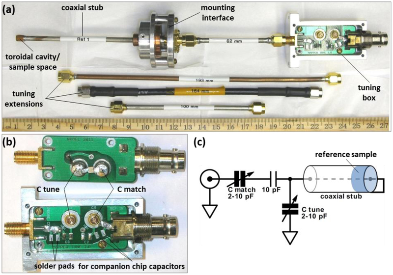
The reference channel (Figure 5) acquires the signal from the static sample close to the center of the magnet. The reference probe utilizes a toroidal cavity resonator [32] built into the end of a semi-rigid coaxial cable to fit within the 0.25 in hole in the traveling probe. To form the toroidal cavity, a small copper cup with two vent holes is soldered to both the shell and the center conductor of a short coaxial stub. The void under the cup works as both the resonator and the sample space. Sample is injected into the 3.6 mm OD, 2.4 mm ID, 1 mm deep cavity with a syringe through a small hole in the cup while the air vents out through the other hole. The holes are then sealed with putty to keep the sample inside.
Figure 5.
Static channel of the mapping probe: (a) – reference channel (shown here with 583 MHz tuning extension), and tuning extensions for 389, 466, and 505 MHz (top to bottom); (b) – front and back of identical tuning boards for static reference channel; (c) – circuit diagram.
Electrically, the stub is a transmission line shorted by the toroidal cavity. Such a transmission line has multiple resonance frequencies corresponding to standing waves, starting with λ/4 and separated by λ/2. For ~350 – 600 MHz we use the ¾ λ resonance. We change frequency range by selecting tuning extensions of appropriate length (Figure 5a), and fine-tune and match to 50 Ω with variable capacitors on the tuning board (Figure 5b).
NMR samples for map acquisition
A standard choice of isotope for NMR mapping is 1H due to its high concentration (110.8 mol/L in water) and high sensitivity. We had the appropriate rf hardware for NMR at 1064 MHz in the Keck resistive magnet, and we used the 1H signal to map and correct this magnet. However, we found that the rf connectors in our field mapping system perform better at lower frequency. When the time came to map and correct the 36 T SCH magnet we decided not to acquire the equipment needed to operate the mapper at 1.2 and 1.5 GHz, but instead to utilize a 7Li sample similar to what we had chosen for use as an external lock sample [33].
7Li is a high-sensitivity spin-3/2 isotope, with a natural abundance of 92.5% and γ7Li/γ1H ratio of 0.389. Lithium salts have high solubility in water. Our external lock sample contains 25.3% (6.84 mol/L) LiCl solution. Assuming constant rf sample coil efficiency, the 7Li signal for this solution is about 4.3% of that of 1H. This level of signal was sufficient for the mapper channel. We increased concentration to 38% for the reference channel to offset the lower efficiency of the toroidal cavity. LiCl solutions were doped with MnCl2 in order to reduce relaxation time and speed up acquisition of FIDs.
The target operating fields of the SCH magnet (23.5, 28.2, and 35.2 T) correspond to 7Li resonance frequencies of 388, 466, and 583 MHz. At these frequencies we were able to use readily available NMR rf hardware. Reflections at connectors are reduced at lower frequency which simplified tuning. For the same rf pulse length, the fractional bandwidth of the excitation pulse is larger at lower frequency. We ran most map acquisitions with ~25 W rf pulse power into NMR channels. While 90 degree time for 7Li was 8 μs (in the traveling channel), we often used shorter pulses to gain more bandwidth due to large field variations along the mapping trajectory of the unshimmed magnet. Having both 1H and 7Li in the same sample, we found it practical to test the mapper hardware immediately before use by pausing the magnet ramp briefly at low field and acquiring the 1H signal from the solvent. With so many benefits, the reduction in signal intensity seems to be a good trade off.
Results
NMR signal in the SCH magnet
NMR mapping using the setup described above requires NMR signal of sufficient strength. Here we demonstrate a single 1H resonance and a single 7Li resonance from our mapping NMR sample. With the mapper probe tuned to 466.6 MHz, we observed proton signal at 11 T and 7Li signal at 28.2 T from aqueous lithium chloride (Figure 6). Similarly, we observed 1H and 7Li signals at 388.6 MHz and 583.0 MHz at respective field strengths.
Figure 6.
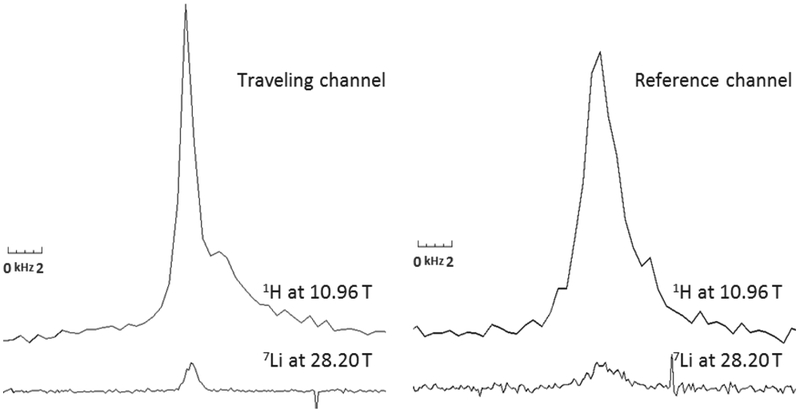
1H (H2O) and 7Li (LiCl aq.) NMR lines in traveling channel (left) and reference channel (right) acquired at 466.6 MHz in unshimmed SCH magnet. Magnetic field strength is 10.96 T for 1H signal from solvent (water), and 28.20 T for 7Li signal from dissolved LiCl. No line broadening was applied to better show the relative sensitivity and linewidth. Note that homogeneity is different between the two fields due to difference in temperature profiles of the magnet. The reference sample occupies a larger volume resulting in a broader line. For mapping purposes, artifacts and spectrometer noise would be reduced using exponential multiplication before Fourier transformation.
A typical line width without shims is 1 kHz in the traveling channel and 1.6 kHz in the reference channel. The difference is most likely due to the larger volume occupied by the reference sample. The traveling sample is sealed in a 0.8 mm ID capillary and restricted to 1 mm length, while the reference sample is injected into a 2.4 mm ID × 1 mm long cavity. In preliminary measurements before resistive coils in the SCH magnet were realigned [26] we observed line widths of up to 6 kHz.
For a fully shimmed magnet, we observed a 50 Hz line width from a D2O sample in 2.0 mm OD, 1.49 ID MAS rotor where the sample is restricted to 5.23 mm length (Figure 7). Spinning at the magic angle reduced the line width to 27 Hz. The base line of the signal is significantly distorted due to field fluctuations which were later reduced by an active field regulation system [18].
Figure 7.
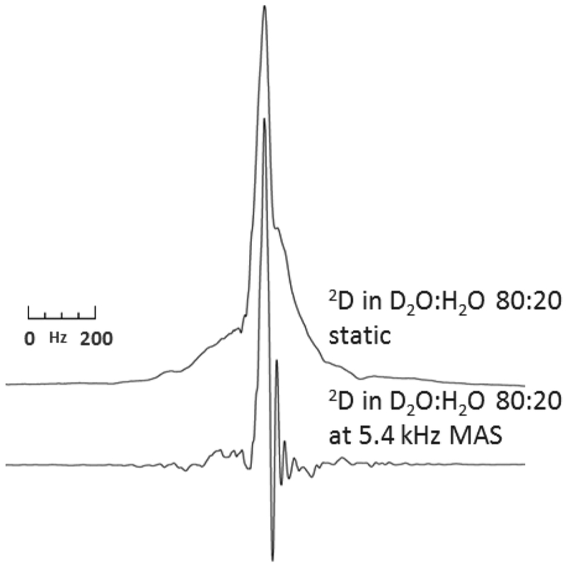
Single scan 1D spectra of deuterium at 230.3 MHz (35.2 T) in the fully shimmed SCH magnet acquired with a 2 mm MAS probe in static and spinning modes. The sample was at room temperature, spectra were acquired following a 2 μs single pulse with an acquisition time of 160 ms and 300 ms for static and spinning spectra, respectively. Spectra processed with 5 Hz exponential decay. The artifacts to the right of the resonance peak are due to the fast (60 Hz) field fluctuations in the magnet
Differential map vs. single-channel NMR map in the SCH magnet
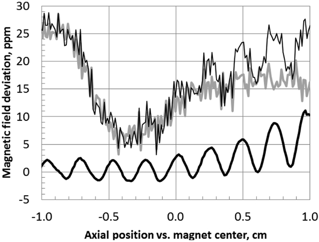
The precision of the single-channel NMR field maps acquired in powered magnets is limited by the level of temporal field fluctuations within the time span of the acquisition. It takes about 5 minutes to record a map over a ±1 cm trajectory, with about 1.4 s interval between scans. An example data set recorded on the stationary reference channel (gray trace in Figure 8) shows a 25 ppm field variation during map acquisition. Field fluctuations between adjacent points in this set reach 7 ppm – notably above the 1 ppm target homogeneity for the SCH magnet. In water-cooled DC magnets there are several sources of fluctuations. The 60 Hz component originates in the hum of the power line. DC power supply electronics introduce 1/f noise which produces substantial fluctuations in the 1-10 Hz range. Both the temperature and the flow rate of the magnet cooling water are subject to changes, too, and both may depend on the mode of operation of other resistive magnets at the facility.
Figure 8.
Reference mapping advantage: uncorrected (thin) and corrected for field fluctuations (bold) helical map of SCH magnet at 28.2 T with a passive shim set. Reference channel data in gray.
Temporal fluctuations make spatial field variation barely discernable in data acquired on the traveling channel. However, subtracting the two curves in Figure 8 point by point reveals a smooth line with 7.5 ppm homogeneity across ± 0.5 cm range. The resulting clear sinusoidal component is characteristic of a linear radial term which can be corrected with shims of appropriate strength.
NMR field maps of powered magnets and results of convergence
Maps and convergence of 25 T Keck resistive magnet
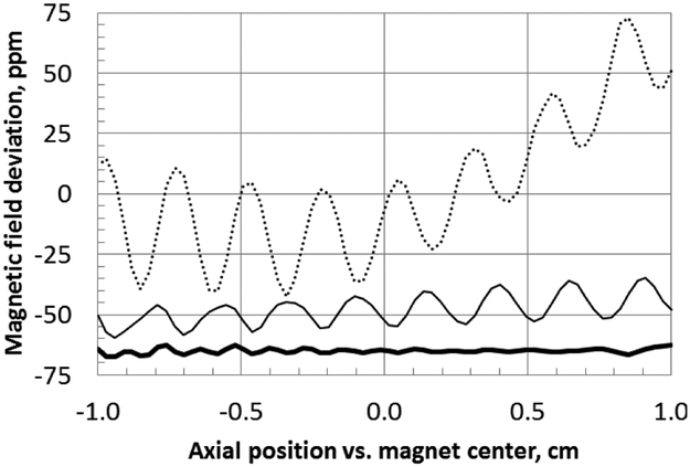
In order to test both the differential field mapping approach and the use of a combined passive/active shim system for correction of Bitter-type magnets, we mapped and corrected the 25 T Keck resistive magnet. The magnet had been previously shimmed in 2000 [23]. In this earlier attempt, a set of ferroshims was mounted on the outside of the magnet bore and provided correction to 12 ppm in 1 cm dsv with the magnet at full field, in spite of the fact that the Bitter coils configuration changed somewhat between the field map and the shim installation. Because of its location, removing or replacing shim tube required partial disassembly of the magnet, thus making changes to ferroshims impractical. For this project, we replaced the bore tube/ferroshim assembly with a blank tube and mapped the magnet, measuring the field shown in Figure 9. Passive ferromagnetic shims installed on the NMR probe cover provided correction from 61 ppm down to 19 ppm over a 1 cm diameter, 1 cm long cylinder. For these and all other maps in this report, we report inhomogeneity as the maximum variation along the 1 cm long helical trajectory. A set of low order resistive shims installed in the bore of the magnet was adjusted to provide further correction to 2.3 ppm. Table 1 shows the field inhomogeneity by term for the background field, after correction with passive shims, and corrected with both passive and active shims. Although the final convergence in the Keck magnet was not quite 1 ppm, it was judged to be near enough to validate the differential mapping and combined passive/active field correction approaches.
Figure 9.
1-cm diameter helical maps of Keck magnet at 25.0 T; dotted – map of background field, solid - with passive shims, solid bold - fully shimmed. Traces are offset for clarity
Table 1.
Field inhomogeneity in Keck resistive magnet at 25.0 T
| Background field |
Field corrected with passive shims |
Best convergence |
|
|---|---|---|---|
| Inhomogeneity in 1 cm long ø1 cm cylinder, ppm | 61.4 | 19.4 | 2.30 |
| Shim term contribution | |||
| Z, kHz/cm [ppm/cm] | −37.0 [−34.8] | −5.9 [−5.5] | 0.1 [0.1] |
| Z2, kHz/cm2 [ppm/cm2] | 59.3 [55.7] | 2.2 [2.0] | 1.7 [1.6] |
| X and Y, kHz/cm [ppm/cm] | 40.0 [37.6] | 14.2 [13.4] | 0.1 [0.1] |
| ZX and ZY, kHz/cm2 [ppm/cm2] | 41.7 [39.2] | 10.7 [10.1] | 1.6 [1.5] |
Maps and convergence of Series-Connected Hybrid magnet at 23.5, 28.2, and 35.2 T
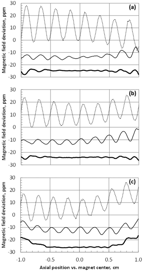
We used our experience in mapping and shimming the Keck magnet to correct the newly built SCH magnet at three different fields. To our advantage, background field inhomogeneity in the SCH magnet is at least two-fold lower than in the Keck magnet. The background and corrected field terms are shown in Table 2, and the helical field maps are in Figure 10.
Table 2.
Field inhomogeneity in SCH powered magnet
| Base field | With passive shims |
Best convergence | |
|---|---|---|---|
| SCH magnet at 23.5 T | |||
| Inhomogeneity in 1 cm long ø1 cm cylinder, ppm | 18.8 | 6.28 | 0.88 |
| Shim term contribution | |||
| Z, kHz/cm*) [ppm/cm] | −5.20 [−5.20] | 0.44 [0.44] | −0.17 [−0.17] |
| Z2, kHz/cm2 [ppm/cm2] | 13.8 [13.8] | −3.45 [−3.45] | 0.36 [0.36] |
| X and Y, kHz/cm [ppm/cm] | 15.5 [15.5] | 5.08 [5.07] | 0.14 [0.14] |
| ZX and ZY, kHz/cm2 [ppm/cm2] | 4.72 [4.72] | 4.08 [4.07] | 0.17 [0.17] |
| SCH magnet at 28.2 T | |||
| Inhomogeneity in 1 cm long ø1 cm cylinder, ppm | 19.7 | 7.53 | 0.89 |
| Shim term contribution | |||
| Z, kHz/cm [ppm/cm] | 1.78 [1.48] | −4.00 [−3.33] | −0.31 [−0.26] |
| Z2, kHz/cm2 [ppm/cm2] | 4.23 [3.52] | 3.82 [3.18] | 0.21 [0.17] |
| X and Y, kHz/cm [ppm/cm] | 22.4 [18.7] | 5.15 [4.28] | 0.20 [0.17] |
| ZX and ZY, kHz/cm2 [ppm/cm2] | 7.52 [6.25] | 6.60 [5.49] | 0.09 [0.08] |
| SCH magnet at 35.2 T | |||
| Inhomogeneity in 1 cm long ø1 cm cylinder, ppm | 29.2 | 4.69 | 0.94 |
| Shim term contribution | |||
| Z, kHz/cm [ppm/cm] | 8.97 [5.97] | −3.03 [−2.01] | −0.03 [−0.02] |
| Z2, kHz/cm2 [ppm/cm2] | −4.97 [−3.31] | 4.74 [3.15] | 0.22 [0.15] |
| X and Y, kHz/cm [ppm/cm] | 35.7 [23.7] | 1.82 [1.21] | 0.02 [0.02] |
| ZX and ZY, kHz/cm2 [ppm/cm2] | 6.42 [4.27] | 9.68 [6.44] | 0.22 [0.15] |
) Field inhomogeneity units are based on 1H signal frequency
Figure 10.
1-cm diameter helical maps of SCH magnet at 35.2 T (a), 28.2 T (b), and 23.5 T (c); dotted - map of the background field, solid - with passive shims, solid bold - fully shimmed. Traces are offset for clarity.
Modern resistive magnets of Bitter and Florida-Bitter design are typically constructed of several nested stacks of circular plates. The SCH resistive insert uses four such stacks, labeled from inner to outer as coils A, B, C, and D. The high homogeneity of the SCH resistive insert is achieved in part by inverting the sign of the Z2 term in coils A and B so that the resulting second-order gradient is cancelled [26]. This cancellation relies on the precise relative alignment of the coils. A small radial misalignment produces a radial gradient of the field, while axial misalignment results in a linear Z term. Construction of the SCH magnet involved a step when the position of the A/B coil assembly was adjusted with respect to the C/D coil assembly based on the preliminary NMR map in order to minimize linear axial gradient.
Axial alignment of the coils, however, slightly changes with the temperature of the magnet cooling water. In an axially cooled magnet such as the SCH, outlet temperature increases with the magnet current. We see a clear trend in the value of Z correction needed between the three operating fields, with the lowest absolute value at mid-field (28.2 T).
Strong low-order field inhomogeneity was corrected using ferromagnetic shims attached to the NMR probe covers. We generated passive shim patterns with linear and second-order axial terms (Z and Z2), and a first-order radial term (X-type) for each of the three fields. Unlike Keck, there was no need for a ZX term in the passive shims for the SCH magnet. With passive shims only, the inhomogeneity was reduced to 6.3, 7.5, and 4.7 ppm at 23.5, 28.2 and 35.2 T. Active shims were adjusted to correct the field further to 0.9 ppm at all three field strengths thus reaching the target specification for the SCH magnet.
Field profile reproducibility
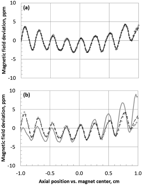
With a high level of field fluctuations one should be concerned whether scan-to-scan and day-to-day data are reproducible. We report that consecutive differential maps acquired in the SCH magnet with passive shims show little to no deviation (Figure 11a). Maps acquired six days apart (Figure 11b, dashed line and circles) are identical except for a small deviation outside the ± 0.5 cm range. This deviation may be caused by an uncertainty in the resonance peak position on a significantly broadened line or due to loss of sample from the reference channel. Good overlap between maps across several days, with mapping hardware and shims removed and then reinstalled in the magnet, shows that both the field of the magnet and position of the ferroshim sets are highly reproducible. This confirms that the SCH magnet can be used for high-resolution NMR spectroscopy with the shimming approach reported in this paper.
Figure 11.
Differential maps and passive shims reproducibility in SCH magnet at 28.2 T: (a) three consecutive scans on February 3, 2017; (b) scans on three different days: dashes – February 03, circles – February 09, solid gray – March 02. An inadvertent shift of the magnet coils during maintenance on February 24 caused a small change in the field profile.
Within the time period of mapping and convergence of the SCH magnet the flange of the resistive insert housing was opened to replace a leaking o-ring. Even though personnel did not touch the resistive magnet coils, this operation caused a small but noticeable change (from 6.4 to 7.5 ppm in 1 cm dsv with the same passive shims set) in the magnetic field homogeneity (Figure 11b, gray line). Field inhomogeneity was still within the range of correction by the resistive shims. The largest changes were in terms Z2 (from 2.7 to 3.2 ppm/cm2) and X(Y) (from 2.6 to 4.3 ppm/cm). This level of sensitivity of the magnetic field profile to maintenance operations validates our decision to make passive shims easily replaceable by building them on the covers for the NMR probes.
Conclusions
We demonstrated successful operation of the field mapping apparatus equipped with a reference NMR channel, based on a single transmitter, dual receiver NMR acquisition. Using this system in differential mode we acquired NMR maps of two powered high-field magnets of Florida-Bitter design despite the amplitude of the magnetic field fluctuations being comparable to the spatial variations in the unshimmed field of these magnets across the volume of interest. Moreover, we achieved record convergence of these magnets, to 2.3 and 0.9 ppm in 1 cm dsv, which is significantly below the level of temporal fluctuations.
Homogeneity of 0.9 ppm reached on the Series-Connected Hybrid magnet enables high-resolution solid-state NMR spectroscopy for studies of the structure of materials and oriented biological samples at 35.2 T (1.5 GHz 1H frequency) – 1.5 times as high as on the next highest field available to NMR scientists. The SCH magnet with the shim setup described here has produced a number of publications in just two years since reaching its target field [33–38].
With the current state of magnet technology limiting the maximum field available on persistent superconducting NMR magnets to 23.5 T, it is anticipated that powered high-temperature superconducting magnets [39–41] will be used for ultra-high field NMR spectroscopy along with resistive-superconductive hybrid magnets. The hardware and techniques presented here will be applicable for mapping and correction of such systems as well.
Supplementary Material
Figure 2.
Dual-channel NMR mapping setup. Tecmag Discovery NMR spectrometer in single transmit/dual receive mode is interfaced with FMU controller from Resonance Research, Inc.
Highlights.
Differential technique enables NMR mapping of powered water-cooled resistive magnets
We combined ferroshims and resistive shims to shim two high-field Bitter-type magnets
25 T resistive Keck magnet reached 2.3 ppm in 1 cm diameter spherical volume (dsv)
Series-Connected Hybrid magnet reached 0.9 ppm in 1 cm dsv at 23.5 T, 28.2 T, 35.2 T
Acknowledgements
A portion of this work was performed at the National High Magnetic Field Laboratory which is supported by National Science Foundation Cooperative Agreement DMR-1157490 and the State of Florida. SCH magnet construction was funded by the NSF grant DMR-0603042 and performed by the MS&T department at the NHMFL. We are grateful for support from the NIH, award P41GM122698.
We would like to thank the MS&T department and especially Mark Bird and Jack Toth for their contributions in defining the SCH shim system. We thank Jason Kitchen, Steve Ranner and Richard Desilets of the NHMFL NMR User Program for their outstanding technical support. We thank Satish Vemaraju for writing the VBScript application. We would like to thank administrative, engineering, and support personnel at the NHMFL for creating a productive working environment.
Footnotes
Publisher's Disclaimer: This is a PDF file of an unedited manuscript that has been accepted for publication. As a service to our customers we are providing this early version of the manuscript. The manuscript will undergo copyediting, typesetting, and review of the resulting proof before it is published in its final citable form. Please note that during the production process errors may be discovered which could affect the content, and all legal disclaimers that apply to the journal pertain.
References
- [1].Anderson WA, Electrical Current Shims for Correcting Magnetic Fields, Review of Scientific Instruments. 32 (1961) 241–250. doi: 10.1063/1.1717338. [DOI] [Google Scholar]
- [2].Roméo F, Hoult DI, Magnet field profiling: Analysis and correcting coil design, Magnetic Resonance in Medicine. 1 (1984) 44–65. doi: 10.1002/mrm.1910010107. [DOI] [PubMed] [Google Scholar]
- [3].Starewicz PM, Hillenbrand DF, Apparatus for mapping a static magnetic field, US4949044A, 1990. https://patents.google.com/patent/US4949044/en (accessed November 5, 2018).
- [4].Starewicz PM, Hillenbrand D, Apparatus for mapping static magnetic fields, US5313164A, 1994. https://patents.google.com/patent/US5313164/en (accessed November 5, 2018).
- [5].Battocletti JH, Kamal HA, Myers TJ, Knox TA, Systematic passive shimming of a permanent magnet for P-31 NMR spectroscopy of bone mineral, IEEE Trans. Magn. 29 (1993) 2139–2151. doi: 10.1109/20.221037. [DOI] [Google Scholar]
- [6].Hammer BE, Magnetic field mapping with an array of nuclear magnetic resonance probes, Rev. Sci. Instrum. 67 (1996) 2378–2380. doi: 10.1063/1.1147005. [DOI] [Google Scholar]
- [7].Metrolab 3045 Datasheet, (n.d.). http://www.gmw.com/magnetic_measurements/MetroLab/MFC-3045_Support.html (accessed November 5, 2018).
- [8].Ntoutoume TA, Deguin A, Lapray C, Briguet A, Switched multiprobe NMR system for magnetic field mapping, J. Phys. E: Sci. Instrum. 22 (1989) 557. doi: 10.1088/0022-3735/22/8/005. [DOI] [Google Scholar]
- [9].Soghomonian V, Sabo M, Powell A, Murphy P, Rosanske R, Cross TA, Schneider-Muntau HJ, Identification and minimization of sources of temporal instabilities in high field (> 23 T) resistive magnets, Rev. Sci. Instrum. 71 (2000) 2882–2889. doi: 10.1063/1.1150707. [DOI] [Google Scholar]
- [10].Bird MD, Bole S, Dixon I, Eyssa YM, Gao BJ, Schneider-Muntau HJ, The 45T hybrid insert: recent achievements, Physica B: Condensed Matter. 294-295 (2001) 639–642. doi: 10.1016/S0921-4526(00)00734-1. [DOI] [Google Scholar]
- [11].Hung I, Shetty K, Ellis PD, Brey WW, Gan Z, High-field QCPMG NMR of large quadrupolar patterns using resistive magnets, Solid State Nuclear Magnetic Resonance. 36 (2009) 159–163. doi: 10.1016/j.ssnmr.2009.10.001. [DOI] [PubMed] [Google Scholar]
- [12].Pauvert O, Fayon F, Rakhmatullin A, Krämer S, Horvatić M, Avignant D, Berthier C, Deschamps M, Massiot D, Bessada C, 91Zr Nuclear Magnetic Resonance Spectroscopy of Solid Zirconium Halides at High Magnetic Field, Inorganic Chemistry. 48 (2009) 8709–8717. doi: 10.1021/ic9007119. [DOI] [PubMed] [Google Scholar]
- [13].Gan Z, Kwak H, Bird M, Cross T, Gor’kov P, Brey W, Shetty K, High-field NMR using resistive and hybrid magnets, J. Magn. Reson. 191 (2008) 135–140. [DOI] [PubMed] [Google Scholar]
- [14].Gan Z, Gor’kov P, Cross TA, Samoson A, Massiot D, Seeking higher resolution and sensitivity for NMR of quadrupolar nuclei at ultrahigh magnetic fields, J. Am. Chem. Soc. 124 (2002) 5634–5635. [DOI] [PubMed] [Google Scholar]
- [15].van Bentum PJ, Maan J, van Os JW, Kentgens AP, Strategies for Solid-State NMR in High-Field Bitter and Hybrid Magnets, Chem. Phys. Lett. 376 (2003) 338–345. doi: 10.1016/S0009-2614(03)01014-5. [DOI] [Google Scholar]
- [16].Sigmund EE, Mitrovic VF, Calder ES, Thomas GW, Bachman HN, Halperin WP, Kuhns PL, Reyes AP, Inductive Shielding of NMR Phase Noise, J. Magn. Reson. 159 (2002) 190–194. doi: 10.1016/S1090-7807(02)00012-5. [DOI] [PubMed] [Google Scholar]
- [17].Sigmund EE, Calder ES, Thomas GW, Mitrovic VF, Bachman HN, Halperin WP, Kuhns PL, Reyes AP, NMR Phase Noise in Bitter Magnets, Journal of Magnetic Resonance. 148 (2001) 309–313. doi: 10.1006/jmre.2000.2246. [DOI] [PubMed] [Google Scholar]
- [18].Li M, Schiano JL, Samra JE, Shetty KK, Brey WW, Reduction of magnetic field fluctuations in powered magnets for NMR using inductive measurements and sampled-data feedback control, J. Magn. Reson. 212 (2011) 254–264. doi: 10.1016/j.jmr.2011.05.010. [DOI] [PubMed] [Google Scholar]
- [19].Lin Y, Ahn S, Murali N, Brey W, Bowers C, Warren W, High-resolution, > 1 GHz NMR in unstable magnetic fields, Phys. Rev. Lett. 85 (2000) 3732–3735. [DOI] [PubMed] [Google Scholar]
- [20].Shapira B, Shetty K, Brey W, Gan Z, Frydman L, Single-scan 2D NMR spectroscopy on a 25 T bitter magnet, Chem. Phys. Lett. 442 (2007) 478–482. [DOI] [PMC free article] [PubMed] [Google Scholar]
- [21].Bird MD, Brey WW, Cross TA, Dixon IR, Griffin A, Hannahs ST, Kynoch J, Litvak IM, Schiano JL, Toth J, Commissioning of the 36 T Series-Connected Hybrid Magnet at the NHMFL, IEEE Trans. Appl. Supercond. 28 (2018) 1–6. doi: 10.1109/TASC.2017.2781727. [DOI] [Google Scholar]
- [22].Bird MD, Bai H, Dixon IR, Gavrilin A, Test Results of the 36 T, 1 ppm Series-Connected Hybrid Magnet System at the NHMFL, IEEE Trans. Appl. Supercond. 29 (2019) 4300105. doi: 10.1109/TASC.2019.2895569. [DOI] [Google Scholar]
- [23].Bird MD, Bole S, Eyssa YM, Can Zhehong, Progress towards 1 ppm at 25 T, IEEE Trans. Appl. Supercond. 10 (2000) 443–446. doi: 10.1109/77.828267. [DOI] [Google Scholar]
- [24].Bird MD, Gan Zhehong, Low resolution NMR magnets in the 23 to 35 T range at the NHMFL, IEEE Trans. Appl. Supercond. 12 (2002) 447–451. doi: 10.1109/TASC.2002.1018440. [DOI] [Google Scholar]
- [25].Bird MD, Bole S, Miller JR, Toth J, The Next Generations of Powered Solenoids at the NHMFL, IEEE Trans. Appl. Supercond. 16 (2006) 973–976. [Google Scholar]
- [26].Toth J, Painter TA, Brey WW, Shetty KK, Homogeneity Study for the NHMFL Series Connected Hybrid Magnet System, IEEE Trans. Appl. Supercond. 23 (2013) 4300104. doi: 10.1109/TASC.2012.2230672. [DOI] [Google Scholar]
- [27].Eyssa YM, Bird MD, Gao BJ, Schneider-Muntau H-, Design and analysis of a 25 T resistive NMR magnet, IEEE Trans. Magn. 32 (1996) 2546–2549. doi: 10.1109/20.511392. [DOI] [Google Scholar]
- [28].Painter TA, Bird MD, Bole ST, Trowell AJ, Shetty KK, Brey WW, Resistive shims for high-field resistive and hybrid magnets, IEEE Trans. Appl. Supercond. 18 (2008) 579–582. doi: 10.1109/TASC.2008.920592. [DOI] [Google Scholar]
- [29].Hoult DI, Lee D, Shimming a superconducting nuclear-magnetic-resonance imaging magnet with steel, Rev. Sci. Instrum. 56 (1985) 131. doi: 10.1063/1.1138480. [DOI] [Google Scholar]
- [30].Iguchi S, Yanagisawa Y, Takahashi M, Takao T, Hashi K, Ohki S, Nishijima G, Matsumoto S, Noguchi T, Tanaka R, Suematsu H, Saito K, Shimizu T, Shimming for the 1020 MHz LTS/Bi-2223 NMR Magnet, IEEE Trans. Appl. Supercond. 26 (2016) 1–7. doi: 10.1109/TASC.2016.2519516. [DOI] [Google Scholar]
- [31].Iguchi S, Piao R, Hamada M, Matsumoto S, Suematsu H, Takao T, Saito AT, Li J, Nakagome H, Jin X, Takahashi M, Maeda H, Yanagisawa Y, Advanced field shimming technology to reduce the influence of a screening current in a REBCO coil for a high-resolution NMR magnet, Supercond. Sci. Technol. 29 (2016) 045013. doi: 10.1088/0953-2048/29/4/045013. [DOI] [Google Scholar]
- [32].Rathke JW, Klingler RJ, Gerald RE, Kramarz KW, Woelk K, Toroids in NMR spectroscopy, Prog. Nucl. Magn. Reson. Spectrosc. 30 (1997) 209–253. doi: 10.1016/S0079-6565(96)01037-0. [DOI] [Google Scholar]
- [33].Gan Z, Hung I, Wang X, Paulino J, Wu G, Litvak IM, Gor’kov PL, Brey WW, Lendi P, Schiano JL, Bird MD, Dixon LR, Toth J, Boebinger GS, Cross TA, NMR spectroscopy up to 35.2 T using a series-connected hybrid magnet, J. Magn. Reson. 284 (2017) 125–136. doi: 10.1016/j.jmr.2017.08.007. [DOI] [PMC free article] [PubMed] [Google Scholar]
- [34].Bonhomme C, Wang X, Hung I, Gan Z, Gervais C, Sassoye C, Rimsza J, Du J, Smith ME, Hanna JV, Sarda S, Gras P, Combes C, Laurencin D, Pushing the limits of sensitivity and resolution for natural abundance 43Ca NMR using ultra-high magnetic field (35.2 T), Chem. Commun. 54 (2018) 9591–9594. doi: 10.1039/C8CC05193C. [DOI] [PubMed] [Google Scholar]
- [35].Gan Z, Hung I, Nishiyama Y, Amoureux J-P, Lafon O, Nagashima H, Trebosc J, Hu B, 14N overtone nuclear magnetic resonance of rotating solids, J. Chem. Phys. 149 (2018) 064201. doi: 10.1063/1.5044653. [DOI] [PMC free article] [PubMed] [Google Scholar]
- [36].Keeler EG, Michaelis VK, Colvin MT, Hung I, Gor’kov PL, Cross TA, Gan Z, Griffin RG, 17O MAS NMR Correlation Spectroscopy at High Magnetic Fields, (2017). doi: 10.1021/jacs.7b08989. [DOI] [PMC free article] [PubMed] [Google Scholar]
- [37].Shen J, Terskikh V, Wang X, Hung I, Gan Z, Wu G, A Quadrupole-Central-Transition 17O NMR Study of Nicotinamide: Experimental Evidence of Cross-Correlation between Second-Order Quadrupolar Interaction and Magnetic Shielding Anisotropy, The Journal of Physical Chemistry B. (2018). doi: 10.1021/acs.jpcb.8b02417. [DOI] [PubMed] [Google Scholar]
- [38].Szell PMJ, Bryce DL, Solid-state nuclear magnetic resonance and nuclear quadrupole resonance as complementary tools to study quadrupolar nuclei in solids, Concepts in Magnetic Resonance Part A. 45A (2016) e21412. doi: 10.1002/cmr.a.21412. [DOI] [Google Scholar]
- [39].Iwasa Y, Bascuñáan J, Hahn S, Voccio J, Kim Y, Lécrevisse T, Song J, Kajikawa K, A High-Resolution 1.3-GHz/54-mm LTS/HTS NMR Magnet, IEEE Transactions on Applied Superconductivity. 25 (2015) 1–5. doi: 10.1109/TASC.2014.2363496. [DOI] [PMC free article] [PubMed] [Google Scholar]
- [40].Nishijima G, Matsumoto S, Hashi K, Ohki S, Goto A, Noguchi T, Iguchi S, Yanagisawa Y, Takahashi M, Maeda H, Miki T, Saito K, Tanaka R, Shimizu T, Successful Upgrading of 920-MHz NMR Superconducting Magnet to 1020 MHz Using Bi-2223 Innermost Coil, IEEE Transactions on Applied Superconductivity. 26 (2016) 1–7. doi: 10.1109/TASC.2016.2524466. [DOI] [Google Scholar]
- [41].Marshall WS, Bird MD, Larbalestier DC, McRae DM, Noyes PD, Voran AJ, Walsh RP, Fabrication and Testing of a Bi-2223 Test Coil for High Field NMR Magnets, IEEE Transactions on Applied Superconductivity. 28 (2018) 1–4. doi: 10.1109/TASC.2018.2801296. [DOI] [PMC free article] [PubMed] [Google Scholar]
Associated Data
This section collects any data citations, data availability statements, or supplementary materials included in this article.


