Abstract
Spintronics uses spins, the intrinsic angular momentum of electrons, as an alternative for the electron charge. Its long-term goal is to develop beyond-Moore, low-dissipation technology devices, recently demonstrating long-distance transport of spin signals across ferromagnetic insulators1. Antiferromagnetically ordered materials, the most common class of magnetic materials, have several crucial advantages over ferromagnetic systems2. Antiferromagnets exhibit no net magnetic moment, rendering them stable and impervious to external fields. Additionally, they can be operated at THz frequencies3. Although their properties bode well for spin transport4–7, previous indirect observations indicate that spin transmission through antiferromagnets is limited to only a few nanometers8–10. Here we demonstrate the long-distance propagation of spin-currents through single-crystalline hematite (α-Fe2O3)11, the most common antiferromagnetic iron oxide, exploiting the spin Hall effect for spin injection. We control the spin-current flow by the interfacial spin-bias, tuning the antiferromagnetic resonance frequency with an external magnetic field12. This simple antiferromagnetic insulator conveys spin information parallel to the Néel order over distances exceeding tens of micrometers. This newly-discovered mechanism transports spin as efficiently as the net magnetic moments in the best-suited complex ferromagnets1. Our results pave the way to ultra-fast, low-power antiferromagnet-insulator-based spin-logic devices6,13 that operate, without magnetic fields, at room temperature.
Spin-wave excitations of the magnetic moments, called magnons, can transport spin angular momentum in both ferromagnetic and antiferromagnetic insulators (AFI). In easy axis antiferromagnets, the two degenerate magnon modes have left or right circular polarization, carrying finite, but opposite, angular momenta14. At thermal equilibrium, there is no net transport as these degenerate, equal-frequency magnons cannot be populated separately. In AFI/heavy metal bilayers, however, an interfacial spin-accumulation can generate an imbalance of the magnon population, enabling spin transport12,15. Such a “spin-bias”, along either the Néel vector n or the field induced magnetization m, could efficiently excite or annihilate the magnon modes depending on the bias sign. This potentially enables one to probe the antiferromagnetic spin conductance since the magnon modes independently transport spin angular momentum. In parallel, thermal excitations by Joule heating could propagate magnons, through the spin-Seebeck conductance, in the presence of a field induced net magnetization m16,17. Low magnetic damping has been reported for AFIs3,18, thus these materials naturally lend themselves to efficient long-distance spin transport experiments despite lacking direct observations8–10.
In a recent report, signatures of long-distance spin-superfluid, rather than diffusive, transport through an antiferromagnet were claimed19, based on only thermal transport, without detecting the expected accompanying spin-injected transport signal. As discussed recently20,21, other contributions such as spatially-extended thermal gradients can explain non-local thermal signals. By achieving the first long-distance spin transport by spin-injection, we unambiguously demonstrate that it is consistent with diffusive rather than superfluid transport, accompanied by a thermal signal that decays over even longer distances (as discussed below and in the methods). Our results clearly rule out spin-superfluidity but demonstrate that long-distance, diffusive spin transport through an antiferromagnet is possible at elevated temperatures.
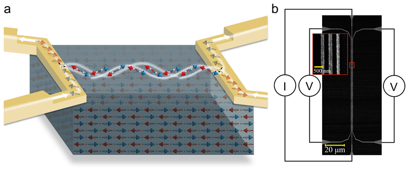
To investigate the spin transport mechanisms in AFIs, we use a non-local geometry1 of platinum (Pt) wires on a single crystal of α-Fe2O3 (Fig. 1 (a)). A charge current, I, passes through a Pt wire, inducing two effects: (i) The spin-Hall effect (SHE) produces a transversal spin-current, leading to a spin-accumulation μ, at the Pt/α-Fe2O3 interface22. This accumulation may couple to the AFI order, generating a spin-current carrying net angular momentum (see Fig. 1 (a)). (ii) Joule heating of the Pt wire induces a lateral temperature gradient ΔT, which generates a spin-Seebeck induced thermal spin-current. Ultimately, the non-local voltage, V = Vel +Vth, is a combination of both spin-current effects detected at a non-local Pt wire via the inverse SHE (ISHE)22. The even component, quadratic in current, related to the spin-Seebeck conductance 𝑆, can be determined from Vth = (V(I+) + (V(I−))/2, and the odd component, linear in current, describing the spin conductance G, from Vel = (V(I+) − (V(I−))/2, to remove any thermal contributions20. The non-local signals Vth and Vel arise from spin-currents carrying angular momentum along the antiferromagnetic Néel order n = (m1-m2)/2 and magnetic field induced moment m = (m1+m2)/2. We therefore write the non-local resistances Rel = Vel/I (Ω) and Rth = Vth/I2 (V/A2) using a two-channel, phenomenological model (see methods):
| (Eq.1.a) (Eq.1.b) |
where e⊥ is a unit vector normal to the Pt wires, i.e parallel to the current induced spin-accumulation μ. All four coefficients (Gn, Gm, Sn, Sm) depend generally on the directions of n and m. Finally, it should be noted that Rel, and therefore Gn and Gm, are direct measurements of the spin conductance of the antiferromagnet, which decreases with the distance from injector to detector1.
Fig. 1.
Spin transport in an insulating antiferromagnet (a) Experiment schematic. Two Platinum (Pt) wires on an insulating easy axis antiferromagnet α-Fe2O3. The spin-Hall effect in the left wire generates a spin-accumulation at the Pt/α-Fe2O3 interface breaking the antiferromagnetic symmetry. Transferring angular momentum to the antiferromagnet, this excites magnons which diffuse to the right wire, where the generated spin-current is detected by the inverse spin-Hall effect. (b) SEM image of a typical device with wire spacings of 200 nm and 250 nm. Platinum injector and detector wires, connected to chromium/gold contacts. Current and voltage connections are indicated.
Our study requires full control of the Néel vector n, which cannot be achieved by aligning the magnetization with small external fields such as in ferromagnets. However, in low anisotropy antiferromagnets like α-Fe2O3, one can still control the direction of Néel vector with a field. Above the spin-flop field Hc (of about 6 T at 200K18), the Néel vector reorients perpendicular to the applied field H. We control the antiferromagnetic order by sweeping an in-plane magnetic field along different directions (see methods) to explore the spin transport signal in devices with different injector–detector distances (see Fig. 1 (b) and methods).
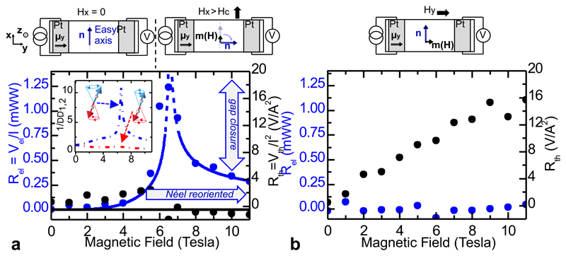
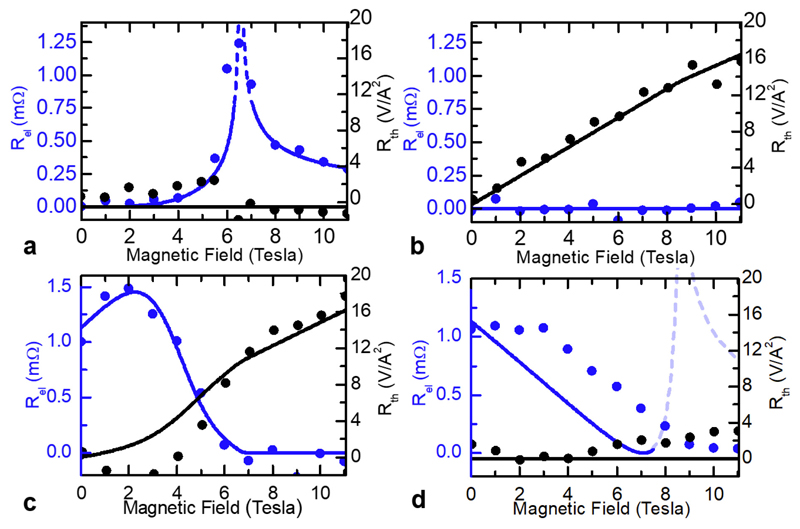
We first consider a device geometry with Pt wires oriented along x, the in-plane axis onto which the easy-axis is projected (see methods). Initially, the Néel vector n is approximately perpendicular to the spin-accumulation, μ = μy. As we sweep H along x, n rotates smoothly and becomes perpendicular to H (along y) when the field reaches Hc. In Fig. 2 (a) we find that the spin conductance signal Rel exhibits a maximum at Hc (around 6 T) and remains non-zero at larger fields, whilst Rth is zero. For H > Hc, Rel is finite due to the reorientation of n along the spin-accumulation μy (see sketch in Fig. 2 (a)). Therefore, we identify the Néel spin conductance Gn as the primary mechanism carrying angular momentum; the spin-accumulation along n excites the antiferromagnetic magnon mode with polarization along the spin accumulation, while annihilating the other. This mechanism also explains the sharp peak of Rel at Hc, when the field compensates the anisotropy energy and the magnon gap of one mode strongly decreases18. A full gap closure theoretically leads to a divergence of Gn. Based on this explanation, we have modelled the experiment as shown in Fig. 2. We find that for our geometry, the magnon gap of one mode is reduced by a factor of 10, illustrating that Gn depends on both the magnon gap and direction of n, and can thus be tailored. Additionally, we find that the Néel spin-Seebeck conductance Sn is negligible, resulting in the absence of Rth below and above Hc.
Fig. 2.
Spin transport at 200 K for platinum wires along x: (a). Magnetic field parallel to wires (along x): The non-local signal Rel (blue) is zero at small fields, exhibits a sharp peak at the spin-flop field Hc, is finite above, and matches a theoretical model (see Methods for more details) based on the lowest magnon gap Δ (solid lines and inset: the inverse gap of one mode is reduced at Hc, whilst the other is enhanced) and μy·n (solid line). The thermal signal Rth remains low (black). (b) Magnetic field perpendicular to wires (along y): The field induced magnetization m is parallel to μ and perpendicular to n. Rel remains zero and Rth increases with field.
We then study a second field direction with H applied along y (Fig. 2 (b)). There now exists a field induced magnetization m parallel to the spin-accumulation μy (Fig. 2 (b)). The absence of Rel is consistent with the prediction that the magnetic spin conductance Gm should be reduced by a factor Tχ<<1 as compared to Gn (with T the temperature and χ the susceptibility)12. However, the spin-Seebeck signal Rth now contributes, increasing linearly with H. The spin-Seebeck conductance S is non-zero only in the presence of m along μ, indicating that Sm >> Sn. In antiferromagnets, H does not break the symmetry of the Néel vector n and the spin-accumulation is only along m, hence, Sn vanishes in the absence of sublattice-symmetry breaking.
We initially conclude that a spin-current propagates through an AFI, mediated by the Néel spin conductance Gn, and the magnetic spin-Seebeck conductance Sm (full angular scans with theoretical fits in the methods). Contrary to ferromagnets1,24, the different spin conductances thus rely on two different magnetic order parameters, n and m, so that spin-injected and thermal spin currents could be controlled separately only in antiferromagnetic spin-logic devices13,25.
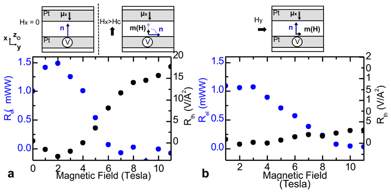
The application of strong fields is cumbersome so we consider platinum wires along y, i.e perpendicular to the easy-axis at zero applied field, as shown in Fig. 3 (a-b). We first analyze this geometry for H applied along x, shown in Fig. 3a. The striking feature here is the presence of a strong signal Rel at zero applied field due to the easy axis orientation where n is already parallel to μx whilst the spin-Seebeck signal Rth increases only above Hc, when a sizeable field induced moment m along μx appears. This observation confirms the high field measurements in the previous geometry: a large Néel spin conductance Gn exists under spin bias, even without a strong reduction of the magnon gap. For H along x (see Fig. 3(a)), the sharp drop of Rel at larger fields reflects the reorientation of n along the wire (y-direction), perpendicular to μx. This field-free spin-transport demonstrates the potential of antiferromagnets for spintronic applications.
Fig. 3.
Spin transport at 200 K for platinum wires along y: (a). Magnetic field perpendicular to wires (along x): The non-local signal Rel (blue) is finite at low fields, sharply decreasing at the spin-flop when the Néel vector n aligns perpendicular to the spin-accumulation μx. The spin-Seebeck signal Rth (black) is initially zero, enhancing at the spin-flop, when a field induced magnetization m emerges along μx. (b). Magnetic field parallel to wires (along y): Rel decreases with applied magnetic field as n re-orientates out of the (xy) plane at large fields. Rth remains zero as m is always perpendicular to μx.
Then, we apply the field along y. In Fig. 3 (b), Rth remains zero as the field is applied parallel to the platinum wires, whilst Rel is again finite as the Néel order is insensitive to small fields. Thus, Rel reveals strongly distinct field dependences for the two device geometries. This shows that active control of the Néel order direction is key for spin transport, which is likely to be problematic in multi-domain thin films, explaining low efficiency spin transport in previous studies (with our single crystal, mono-domain devices can be considered, see methods). We note that the signal amplitude at small fields is comparable to the signal at the reduced magnon gap, possibly arising from different interface transmissivities (Methods). Another intrinsic contribution to the field-dependence conceivably comes from spin-relaxation processes; at Hc, the changes of the magnon dispersion curve could lead to different dissipation channels.
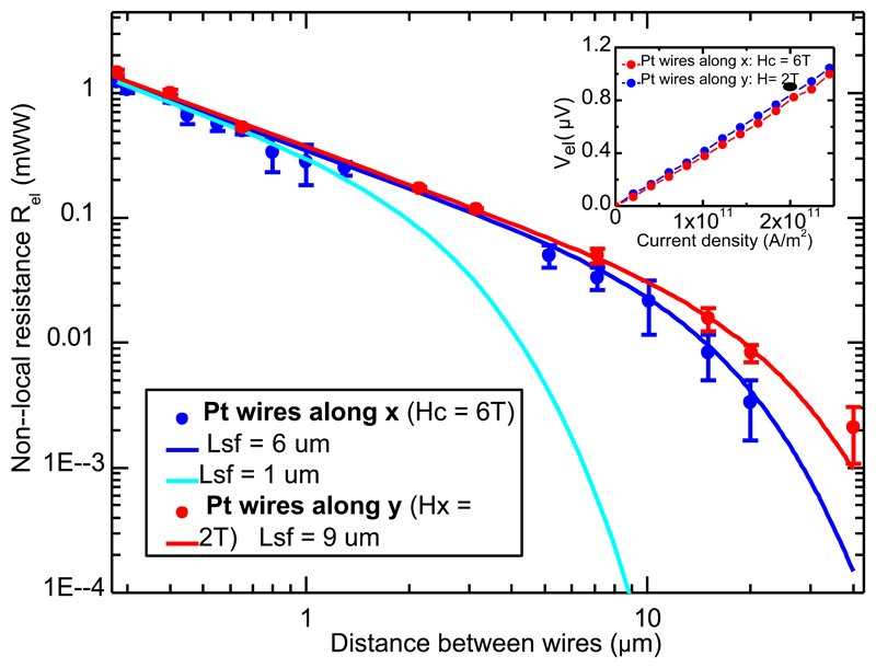
Finally, measuring spin diffusion lengths is a key point to determine the spin transport regime, for which different predictions were made(diffusive15, quasi-ballistic12 or spin-superfluid26,27). We focus in Fig. 4 only on the distance dependence of the spin signal Rel. Fig. 4 presents spin-transport over tens of μm with a linear decay up to a few μm at 200K. Here we want to stress that this feature (alongside the Rth signal up to 80 micrometers, see methods) might lead one to conclude a spin-superfluid regime26,27 as very recently discussed at low temperatures19, even though one certainly observes here diffusive transport. Only for distances larger than the spin diffusion lengths is an exponential amplitude decay predicating diffusive transport observed1. Moreover, Rel is linear with the bias current and presents no threshold, which would exist due to anisotropy effects in the spin-superfluid regime.
Fig. 4.
Distance dependence of the spin signal Rel at 200K. A signal persists for tens of micrometers at both the spin-flop field (Platinum wires along x, blue) and low fields (Platinum wires along y, red). Only the spin signal is shown, fit by a one dimensional spin diffusion equation 1 (the spin-Seebeck signal persists over more than 80 μm, although is difficult to appraise as the heating and spin-current source are delocalized33). Error bars are a combination of the standard error on the mean and the measurement noise floor. (Inset) The spin-bias voltages, Vel, are linear as per a non-equilibrium spin-transport mechanism.
We determine the spin diffusion lengths to be 6 ± 1 μm and 9 ± 2 μm at the spin-flop field and small-applied fields, more than two orders of magnitude larger than reports using AF/FM multilayers9,10. In these systems, magnetic correlations between FM and AFI grains are crucial 28; a Néel order n parallel to μ is critical for efficient spin-transport. Another key issue in AFI thin films is possible multi-domains affecting the mode polarization9,28. In accordance with theoretical works29, our observed micrometer spin-diffusion lengths rely on the low Gilbert damping of α-Fe2O3 (α < 10-4 30), although the question of antiferromagnetic spin-wave relaxation processes remains an open debate 31,32. This is illustrated by the reduction of the spin diffusion length at Hc (9 ± 2 μm compared to 6 ± 1 μm), indicating that the magnon gap reduction at the spin-flop field comes with stronger dissipation channels. Investigations of AFIs with lower damping would reveal the unexplored relaxation processes of antiferromagnetic spin waves and open the possibility of THz magnon spin-logic devices, a path pioneered by our work.
Methods
1. R-cut α-Fe2O3 single crystal and Morin transition
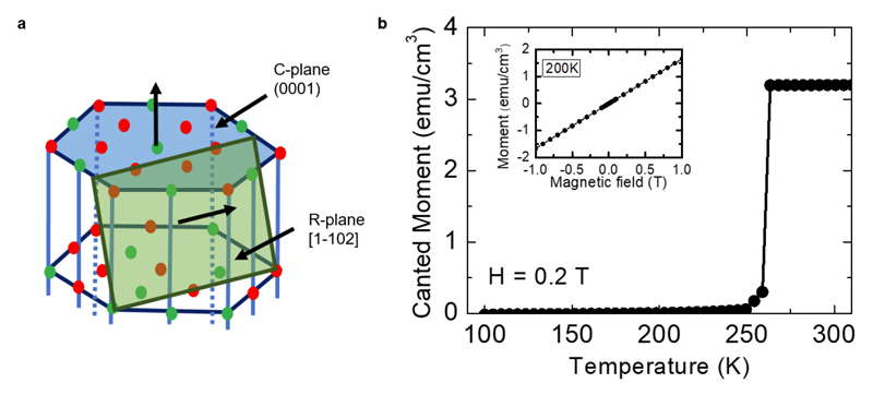
In Extended Data Fig. 1.a, we represent the crystal structure of hematite (α-Fe2O3). Above the Morin temperature, TM, the antiferromagnetic easy-plane is the C-plane (blue) whilst below, the antiferromagnetic easy-axis is along the c-axis (perpendicular to the C-plane). The single crystal of α-Fe2O3, was obtained commercially from SurfaceNet GmbH and is orientated with [1120] out of plane, i.e. the c-axis of the hexagonal structure is tilted ~33 degrees below the surface plane. This orientation was chosen because of the large in-plane projection of the c-axis in addition to the stability of the sample terminating with the R-plane (green plane in Extended Data Fig. 1.a).
In Extended Data Fig. 1.b, the abrupt magnetic transition from the weak ferromagnetic phase to the antiferromagnetic easy axis phase by SQUID magnetometry corresponds to the TM of our single crystal (260K as reported in the literature11,34). Below it, we observe no residual magnetization, indicating the purity of the single crystal. Below TM, the Néel vector is parallel to the DMI vector with no effect on the magnetic moments. Our sample maintains its insulating properties and exhibits no evidence of semiconducting behavior from 300 K down to 4 K. One should note that the Morin transition can be tuned by slightly doping α-Fe2O3 to shift TM to higher (with Ir35 or Sn36 doping) or lower temperatures (with Ti or Ga doping37).
2. Lithography and measurement procedure
The obtained sample was 5 mm x 5 mm x 0.5 mm with a surface roughness of <0.1 nm. It was cleaned with acetone, isopropanol and deionized-water before patterning. The samples were defined using electron beam lithography and the subsequent deposition and lift-off of a 7 nm platinum layer by DC sputtering in an argon atmosphere. The non-local wires were contacted using a bilayer of Cr(6 nm)/Au(32 nm). The geometry consists of three wires 50 μm in length (L) and 350 nm wide with wires patterned parallel and perpendicular to the sample easy axis. The wire separations differed, ranging from 200 nm – 80 μm. Figure 1b of the main text shows an SEM image of a typical device.
For separations of more than 1 μm, a second geometry (with double wire length 2L) was used to limit the geometric impact on the signal. The injection current was also doubled to increase signal to noise. To allow for accurate scaling of the signal, calibration distances of 500 nm were added where the scaled signal is consistent with comparable distances in geometry one.
The sample was mounted to a piezo-rotating element in a variable temperature insert installed in a superconducting magnet capable of 12 T. The field was swept in-plane either parallel or perpendicular to the antiferromagnetic easy axis.
The central wire was used to carry a direct charge current with either positive or negative polarity of 300 μA for devices with a length L (600 μA for 2L length). Due to the SHE, a spin-current flows towards the Pt/α-Fe2O3 interface. The measured voltage was detected in the left and right detector wires using a nanovoltmeter, due to the ISHE creating a charge flow. This voltage was recorded as a function of spatial separation, external field, applied bias current and angle between the charge current and field. The voltage was recorded for both positive and negative injection currents, so that, as a function of time, the current traces a square wave-like signal where a delay was added between reversing the current and the start of data collection to allow for any rise time in the current source and any capacitor-like effects in the nanostructures. The thermal transport signal is independent of current direction whilst the SHE will cause a spin-current with opposite polarizations depending on the current direction, allowing for the separation of the two signals as detailed in the main text as the sum and difference of the two signals.
3. Domain size in the canted antiferromagnetic phase
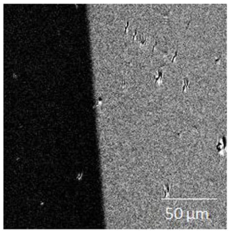
Above the Morin temperature, we can image the canted antiferromagnetic domains by MOKE microscopy. We observe domain sizes of hundreds of microns as seen in Extended Data Fig. 2. Mitsek et al.38 described the emergence of such domains (separated by 180° domain walls) through the Morin transition by the fusion of two antiferromagnetic domains (separated by 90° antiferromagnetic domain walls). Thus, it indicates that the pure antiferromagnetic domains are also of micrometer sizes and it is thus reasonable to model the antiferromagnetic spin transport by assuming a single domain between our platinum wires (particularly at high field).
4. Modelling of the magnetic configurations and of their associated spin-Hall magnetoresistances
a). Modelling of the Néel order and magnetization orientations
Hematite possesses a uniaxial anisotropy and a Dzyaloshinkii-Moriya interaction (DMI), both rotationally invariant around a common axis, x′. Below TM, the anisotropy is along the indicated easy-axis (EA), and at zero field any induced magnetization vanishes, with the Néel order oriented along the EA. We model the macrospin of the α-Fe2O3 crystal by a two spin model, with energy:
| (Extended Data Eq. 1) |
where m1 and m2 are unit vectors representing the magnetic orientation of each sublatice. Here K is the anisotropy, J the exchange, D = Dx′ the DMI, and H the applied field, all with units of energy. The dimensionless Néel order and magnetization are given by n = (m1 - m2)/2 and m = (m1 + m2)/2, respectively.
At zero field, m = 0, while n lies along x′. When a field H is applied along the x′ direction, the α-Fe2O3 is rotationally invariant and admits a simple analytic solution. Below the “spin-flop” field the Néel order lies along the x′ axis, and the magnetization vanishes; when H > Hc, however, the α-Fe2O3 is in a spin-flop phase, with a paramagnetic moment m induced along the x′ direction, and the Néel order perpendicular to m and H. To obtain the magnetic state, we numerically minimize the energy E, Extended Data Eq. 1, with respect to n and m by solving the Landau-Lifshitz-Gilbert equations.
Denoting the sample plane as the x-y plane, the easy-axis x′ makes a ~33° angle with the x axis (see Extended Data Fig. 3.a). We find that when the field H is applied in the y direction (i.e., perpendicular to the EA x′), a paramagnetic moment m is induced along the field. However, the presence of the DMI energy ~D · m x n complicates slightly the situation. The DMI energy is minimized when m x n is collinear with the x′ direction. Thus, the Néel order, which is initially in the x′ direction, rotates at large fields (around 2Hc in the literature) nearly out of the plane in the (xz) plane until it is perpendicular to x′ (see Extended Data Fig. 3.b). One should note here that for an R-plane crystal, the direction of the Néel order is easily controllable and well defined above the spin-flop field (by the intersection between the plane perpendicular to the easy-axis and the plane perpendicular to the applied field), which is not achieved as easily for c-plane and a-plane surfaces by applying an in-plane field.
When the field is applied in the x direction, a typical spin-flop behavior is observed. At small fields the Néel order cants towards the z axis, while a paramagnetic moment m is induced in the (xz) plane (see “1” in Extended Data Fig. 3.c); thus at small fields, m and n lie in the (xz) plane. When the applied field is sufficiently large (around Hc), n is gradually reoriented towards the y direction (see “2” in Extended Data Fig. 3.c below).
b). Theoretical model of spin-Hall magnetoresistance
The local magnetic orientations of α-Fe2O3 in response to an external field H manifest in the SMR of the local platinum wires. In order to show that the numerical orientations of the n and m obtained in the section above are consistent with the experimental SMR measurements (Methods 5), we briefly discuss here a model for the dependence of SMR on n and m.
We write down an expression for the interfacial spin-current js based on symmetry arguments:
| (Extended Data Eq. 2) |
where μ is the spin-accumulation at the interface, the Néel spin-mixing conductance, and and the real and imaginary parts of the magnetic spin-mixing conductance. The assumption of no sublattice symmetry breaking at the interface, allows us to drop all terms linear in n. The first three terms originate from the static orientations of n and m, while is the spin-current arising from thermal spin waves. This spin-current describes the flow of spins between heavy metal electron spins and incoherent AFI spin waves. Hence it facilitates the injection and detection of thermal spin wave currents, and ultimately give rise to Eq. 1. In theoretical treatments of ferromagnetic insulator/HM bilayers, SMR is attributed to the static order parameter n. Similarly, we thus neglect the role of in SMR.
The expression for the spin-current being absorbed by the HM is:
| (Extended Data Eq. 3) |
where E is the applied electric field inside the HM layer (assumed to be uniform in the z direction),σ0 is the bare conductance of the wire, θSH is the spin Hall angle, and the right-hand side is understood to be evaluated at the interface. The general form of the spin-accumulation μ inside the HM wire is obtained from a spin diffusion equation: = Ae-z/λ + Bez/, where λ is the HM spin-flip length.
The parameters A and B and thus μ are obtained by equating Extended Data Eq. 2 and 4. When the coefficients the expression for js is identical to that obtained for a ferromagnet with a real spin mixing conductance, with the Néel order replacing the magnetization. Last, the charge current j flowing through a wire is given by:
| (Extended Data Eq. 4) |
Averaging over the thickness of the HM wires in the z direction and inverting to find E = ρ*jave (where jave is the thickness averaged current) one obtains the 2×2 resistivity tensor ρ, which depends on n and m through A and B.
c. Experimental and theoretical spin-Hall magnetoresistance
i. Platinum wires along x
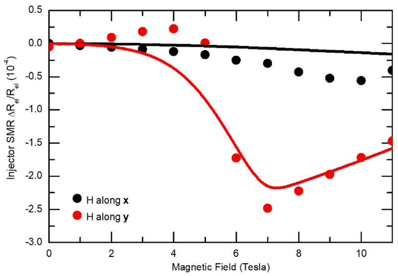
In the injector wire, we measure (with a 2 points detection scheme) the field-induced SMR for a field H parallel (along x) or perpendicular (along y) to the wire as seen in Extended Data Fig. 4. In this configuration, the EA of α-Fe2O3 has a projection along the wire and no projection perpendicular to it at zero applied field.
From the local SMR measurements, we can detect the presence of a spin-flop around 6 T when the field is applied along y, making a 33° angle between the applied field and the EA. From this measurement, we extract an SMR ratio of at Hc. With the theoretical formalism presented previously, we can fit the SMR curves for the two field orientations, reproducing qualitatively both the amplitude of the signals and the magnetic field reorientation at the spin-flop transition.
ii. Platinum wires along y
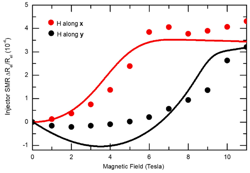
The SMR for Pt wires along y is shown in Extended Data Fig. 5 for fields parallel and perpendicular to the wire. From these curves, we again can extract the SMR ratio, obtaining a value of at the spin-flop, about 2 times the value for the previous orientation. Similarly, the fitted values of the spin-mixing conductances are larger for this device geometry by about a factor 3. Being careful in concluding about the origins of these differences (lithographic effects, interface transmissivities, thermal spin-waves), we note it is in agreement with the larger intrinsic spin-transport signals for this orientation (see Fig. 3 in the main text, and Methods 5).
Furthermore, we notice in the x scan that the experimental and theoretical spin-flop field are both around 6T whilst for the y scan (H perpendicular to the Easy-axis), the theoretical DMI induced reorientation (see Fig. Extended Data Fig. 3.c) is slightly shifted with the experimental one (8T instead of 10T). This discrepancy arises from the difficulty to simultaneously fit these two reorientations (classical spin-flop field and DMI induced reorientation) by considering only the EA and DMI anisotropies.
5. Model for non-local spin-transport signal
Eq. (1) in the main text is a minimal model for two-channel transport by m and n. The factors of (n · e⊥)2 and (m · e⊥)2 in Eq.1.a. arise from the spin injection by the spin-accumulation μ ≈ μe⊥ into the AFI Néel order or magnetization and the subsequent spin injection into the detector; in contrast, the spin-accumulation in the injector wire plays no role in the spin-Seebeck signal, and hence (n · e⊥) and (m · e⊥) in Eq 1. b. All four of the coefficients depend generally on n and m, so sublattice symmetry of the AFI implies Sn(n) = - Sn(-n) etc. Finally, it should be noted that although Rel and Gn and Gm are measured in units of (V/A), both are in fact a measure of the spin conductance of the AFI. As the spin-Seebeck signal is quadratic in current, Rth and therefore Sn and Sm are measured in units of V/A2 but represent a measure of the spin-Seebeck conductance.
Then, Eq. (1) depends on H via the terms, of (n · e⊥), (n · e⊥)2, (m · e⊥) and (m · e⊥)2. Based on the determination of m and n (see Methods 3), one can make the following predictions about the non-local spin signals:
-
-
For wires oriented along x, e⊥ = y and μ ≈ μy. When H is applied in the y direction, n lies in the (xz) plane and m along y (see Extended Data Fig. 2.b). Thus, the non-local signal cannot arise from the Néel order since n · y and (n · y)2 are zero. The non-local signals must then arise from the paramagnetization m, but m vanishes at small fields. Thus we expect an enhanced signal with applied field (see Fig. 2.b). At small fields applied in the x direction, both n and m lie in the (xz) plane (see “1” in Extended Data Fig. 3.c.), so the signal should vanish. As the field is increased, the anisotropy and DMI fields reorient n along the y direction (see “2” in Extended Data Fig. 3.c), opening up the possibility of a signal at higher fields arising from the Néel order (see Fig. 2 (a) in the main text).
For wires are oriented along y, e⊥ = x and μ ≈ μx. When the field is applied in the x direction, one finds that for small fields, n · x is nonzero, giving rise to a non-local signal. At higher fields, n reorients due to DMI and the anisotropy fields and the signal is reduced (see Fig. 3 (b) of the main text). At large fields along y (about 2Hc), n reorients only due to DMI.
Eq. (1) also depends on H through the structural transport coefficients Gn, Gm, Sn and Sm, Gn which present unknown general dependences. However, the field-dependence of these coefficients for fields applied along the easy axis is known from a stochastic Landau-Lifshitz phenomenology12 and drift-diffusive treatment15,39:
-
-The spin conductance G is predicted to diverge as one of the gaps of the two spin wave branches closes12. We thus approximate the low energy behavior of G by:
where G0 is a constant to be determined by fitting the data, and ΔH is the smaller of the two spin wave branch gaps under a field H. To obtain ΔH for a given field, we find the ground state orientations m and n, and then linearize the Landau-Lifshitz-Gilbert equations of motion for m1 and m2 around this state; we thereby find two eigenfrequencies, corresponding to the two main spin wave branches. At zero field, these are the degenerate oscillations of the Néel order, with opposite helicities. At finite field, the degeneracy is lifted (see dashed lines of Fig. 2 (b) of the main text). The theoretical Rel is then determined by the inverse of the lowest magnon gap Δ and by the projection of the spin-accumulation on the Néel vector (μy · n).(Extended Data Eq. 5) -
-
When Gm is set to zero, i.e G ~ Gn, we find that Eq. 1.a and Extended Data Eq. 5 qualitatively reproduce the signal shown in Fig. 2 (a) of the main text, and also the other orientation as shown in Extended Data Fig. 6. Our simple model wherein G0 is field-independent is consistent with the prediction that the dominant contribution to the spin-current is symmetric in field H.
-
-
The data is consistent with Sm ≫ Sn (see below), so we focus on Sm. As Sn is known to have a continuous dependence on the field12,16,39 (unlike Gn), we posit a continuous dependence of Sm as well. Taking the lowest order term, we model Sm ~ S0 as field-independent, as the dominant field-dependence is captured by (m · e⊥).
We show the fits of the data with our model, Gn ~ G0(Hc/ΔH) and Sm ~ S0 in Extended Data Fig. 6. We obtain similar spin-Seebeck conductance coefficients (S0~ 60 V/A2) for the two device geometries, G0 is much larger for platinum wires along y (Fig. 3 of the main text) than for wires along x (Fig. 2 of the main text). This is in accordance with the SMR measurements presented in Methods 3 and fits as Similar to the SMR measurements, the difference of intrinsic spin conductance for the two geometries might arises from the patterning processes, or different transmissivities and anisotropic spin diffusion lengths which are not taken into account in our model.
The only slight discrepancy between our theoretical model and the experiments concerns the high field spin-signal Rel for Extended Data Fig. 6. (d). In this case, the applied field is perpendicular to the easy-axis, and a spin-reorientation happens only at large field due to the presence of the DMI. In our SMR data, this high field reorientation occurs at 10 T (see Extended Data Fig. 5), while in our SMR and non-local fits, it occurs around 8T for our chosen set of K, J and D = Dx′. The fact that this reorientation occurs at larger fields experimentally explains why we do not observe the same increase of the spin-signal as our model predicts. Higher order anisotropy terms could explain why we cannot obtain exactly this magnetic reorientation at its experimental value by using only three parameters (K, J and D). Another contribution to this discrepancy is that the magnetic dynamics change from circular to elliptical, and then to nearly linear at high fields40 applied perpendicular to the easy-axis, an effect that is not taken into account. In easy-axis antiferromagnets like α-Fe2O3, the presence of circularly polarized magnon modes is an essential difference compared to the largely studied family of easy-plane antiferromagnets like the insulating NiO9,10. In the latter case, spin transport was reported only over nanometers distances, not more than for metallic antiferromagnets with larger damping like IrMn29,41, which can be attributed to the easy-plane symmetry of the system, to the presence of disorder in antiferromagnetic thin films and to the inefficient spin-injection in FM/AFM system with non-collinear magnetic orders9,41. Finally, we note here that the spin transport and coupling can also be affected by phonons42, which is currently not explicitly taken into account in our description. However, previous studies on non-magnetic SrTiO3 have not observed any transport beyond the tunneling range9.
6. Spin conductance
To compare the spin conductance in ferromagnetic and antiferromagnetic insulators, we estimate the spin conductance of the AF using the spin-resistor circuit model1,43,44 :
| (Extended Data Eq. 6) |
For the shortest distance (d ~ 300 nm), we obtain a non-local to SMR ratio of Rnl/RSMR ~ 1/1000, about one order of magnitude smaller than for Cornelissen et al.1 (Rnl/RSMR ~ 1/57 for d ~ 300 nm). However, the calculated spin conductance of Pt is higher in our experiment ( compared to ). Then, we obtain a similar spin-resistance ~ 0.02 Ω (with a Pt/α-Fe2O3 interface area A = 1.75*10-11 m-2 and an effective spin-mixing conductance of the Pt/α-Fe2O3 interface, 44 45, which is consistent across both device geometries.
In a bulk crystal, extracting the spin conductivity requires some assumptions compared to thin films. First, the spin channel thickness tc should theoretically be of the order of the spin-diffusion length and not the sample thickness. This implies that no spins are dissipated into the crystal (which was shown not to be correct in the ferromagnetic case as the signal amplitude decreases with increasing film thickness46. If these two assumptions hold for our system, we can extract a spin-conductivity of ~ 105 S/m with channel dimensions of tc ~ lsf ~ 7μm, wc= 50 μm and Lc~ 300 nm. From these first measurements, we can thus ascertain that the antiferromagnetic spin-conductivity is of the order of the ferromagnetic case. For a more quantitative analysis, samples of different thicknesses need to be considered, which is beyond the scope of the present work.
There are three further points, which hamper a quantitative comparison. The platinum spin-conductance varies by one order of magnitude in the literature ( 47,48). Furthermore, the interface properties depend strongly on the surface treatment in ferromagnets48 in addition to our measurements being carried out at 200 K (compared to room temperature in Cornelissen et al.1). Future work is needed to investigate the interface effects and temperature dependence of diffusive transport in antiferromagnets.
7. Angular dependence
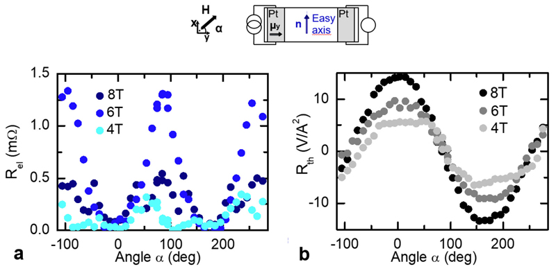
For devices with platinum wires along x, we investigate the symmetry of the two spin transport signals by rotating the sample under a fixed field. In Extended DataFig. 7. a-b, the spin transport and the thermal signals are 90° shifted relative to each other. There, α = 0° (90°) corresponds to H||μ0 (H||Easy-axis), where the spin signal is minimum (maximum) and the thermal signal is maximal (minimum). This confirms the different origins of the two signals to be either Gn or Sm. The spin-bias signal Rel is present for a Néel vector along the spin-accumulation and shows a maximum at the spin-flop field Hc (around 6 T as seen in Extended Data Fig. 7.a) whilst the thermal signal is present for a field induced magnetization along the spin-accumulation and thus linear with the amplitude of the applied field (see Extended Data Fig. 7.b). The spin injection signal shows a sin(α2) dependence as both the injecting (SHE) and detecting mechanisms (ISHE) are α dependent and the signal follows n rather than m as in ferromagnets.
The spin-Seebeck signal Rth exhibits a cos(α) dependence from the ISHE detection but maintains the same symmetry as in ferromagnets due to the similar transport mechanism through the field induced magnetization m.
8. Origin and distance dependence of the Spin-Seebeck signal
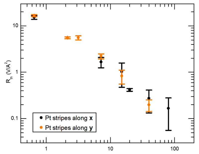
The spin-Seebeck signal Rth shows a similar distance dependence for the two device geometries (Extended Data Fig. 8) illustrating that, far above the spin-flop, the magnon dispersion is quite similar for these two configurations.
Remarkably, the spin-Seebeck signal can be detected up to a distance of 80 microns, with a slower decay as compared to the direct spin-injected signal. Up to 40 μm, the signal decay is linear, which could be associated to spin-superfluidity19 whilst the symmetry of the system (easy-axis and not easy-plane antiferromagnet) as well as the elevated temperature (200 K) allow us to exclude this regime (in addition to the features of the spin-injected signal discussed in the main text).
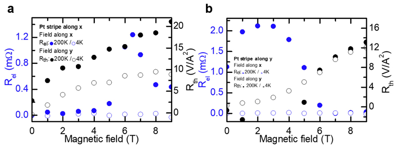
Furthermore, at low temperatures, the spin signal disappears (see blue curves in Extended Data Fig. 9) as expected for a diffusive rather than spin-superfluid regime, which anticipates a large increase as the anisotropy is compensated by either a magnetic field at the spin-flop field or reduced temperature. In parallel, the spin-Seebeck signal persists (see black curves in Extended Data Fig. 9) as reported by Yuan et al.19, who recently claimed to observe spin-superfluid transport in thin films of Cr2O3 from only thermal signals at low temperature. Nevertheless, contrary to their statement, the absence of a spin-injected signal is not associated with poor Pt/AFI interfaces and low spin-mixing conductances and is only due to its diffusive nature as we observe a clear spin-injected transport signal at higher temperature. A reduction of the spin-injected signal whilst maintaining a thermal signal is an effect that has been seen previously in temperature dependent measurements on ferromagnets20,49. This discrepancy between spin-injected and spin-Seebeck signals most probably arise from complex contributions related to the thermal source.
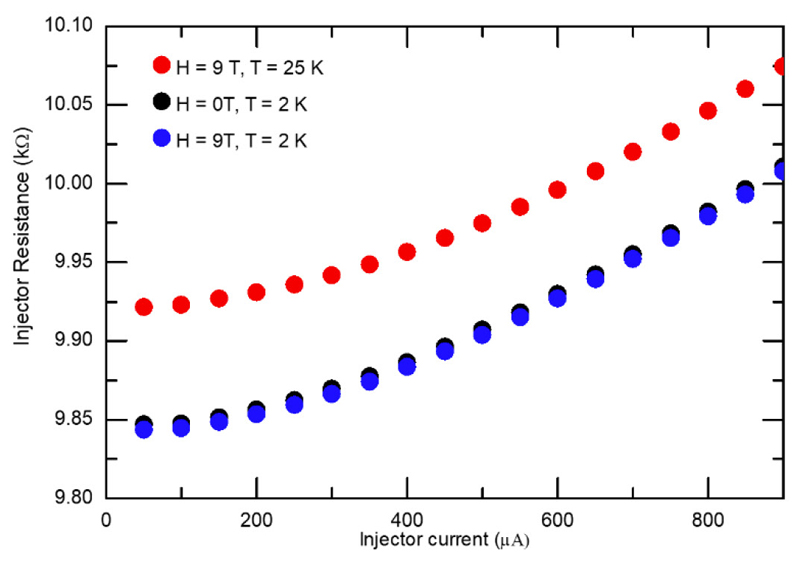
Although one can easily analyze the transport regime from the spin-injected signal (due to the localization of the SHE induced spin-accumulation in the injector), one should be much careful in analyzing the spin-Seebeck signal as discussed in several recent works20,21,46,50. For example, one should take into account that the heating source is not localized to a single point and can generate thermal magnons far from the platinum injector21,33. At low temperatures, the Joule heating (with a current density around 2.8x10¹¹ A/m2 as used in Extended Data Fig. 9, similar to Yuan et al.19) also generates a non-negligible increase of temperature in the injector (of around 20 K for a Helium bath of a few Kelvin), which keeps the injector in the temperature region of the phonon peak as demonstrated in Extended Data Fig. 10. In the entire temperature range, spatially extended thermal gradients are also generated by Joule heating. The non-local thermal signal can also include contributions from thermal magnons generated far from the injector. Furthermore, the spin-Seebeck signal can be driven by a heat flow affected regime when the condition ts≪ λ is not fulfilled (with ts the sample thickness and λ the spin-diffusion length) as shown by Shan et al.21. In this case, the spin-Seebeck signal is dominated by heat backflow in the detector for long-distances. Contrary to ferromagnets, this criteria can also be true in ultrathin antiferromagnetic films for which the effective spin-diffusion can be of a few nanometers due to the presence of magnetic antiferromagnetic domains9,10,41,51, which would also reduce exponentially any spin-superfluid state52. Finally, as seen in the main text, the spin-Seebeck signal arises for the field induced magnetization. Above the spin flop, the magnetic moments orient perpendicular to the magnetic field and the spins cant along the magnetic field. This increases the net magnetization in the direction of the magnetic field and leads to an increase of the magnetic anisotropy, which would destroy any produced spin-superfluid state regardless of origin26.
To conclude, one should be cautious in determining the spin-transport regime from only the Spin-Seebeck signal Rth, particularly in AFM samples.
Extended Data
Extended Data Figure 1.
R-plane hematite. a, Crystallographic structure of hematite, α-Fe2O3. The single crystal that we use has an R-plane termination making a 33° angle with the easy axis [001] of α-Fe2O3. Above the spin-flop, the (111) plane becomes an easy plane. b, Temperature dependency of the magnetization in the single crystal of hematite measured by SQUID. The weak ferromagnetic moment is suppressed below the Morin temperature of 260 K (Inset) At 200 K, below the Morin temperature, we note the complete absence of ferromagnetic moment.
Extended Data Figure 2.
Weak ferromagnetic (or canted antiferromagnetic) domains. Magnetic domains are imaged by MOKE microscopy above the Morin temperature (at 290K) of an R-cut hematite single crystal.
Extended Data Figure 3.
Magnetic states of hematite under a field. a, Initial magnetic state of the R-cut hematite single crystal in its easy axis antiferromagnetic phase at 200 K. The easy-axis is oriented ~33° out-of-plane but only the in-plane projected is relevant. Projection of the easy axis in the (x,y,z) coordinates. b, Evolution of the antiferromagnetic state when a field is applied along y. c, Evolution of the antiferromagnetic state when the field is applied along the x-axis at small and large field H.
Extended Data Figure 4.
Spin-Magnetoresistances for a geometry with platinum wires along the x axis (spin-accumulation μy along y). a, For a magnetic field H along x (grey dots). The jump in resistance at 6 T corresponds to the spin-flop field. b, For a magnetic field H along y (black dots). (The solid lines correspond to regression fit of the H-along-y data of the spin mixing conductances from Extended Data Eqs. 3, 4 and 5, yielding = 12.76 /nm2 and = 74.82 /nm2. The two field directions are fitted together with = 0, and K/J = 0.025 and D/J = 0.011, using λ = 2 nm, θSH = 0.1 and ρ0= 40 μΩ.cm for the normal metal wires)
Extended Data Figure 5.
Spin-Hall Magnetoresistances for a geometry with platinum wires along the y axis (spin-accumulation μx along x) a, For a magnetic field H parallel (grey dots) to the wire. The jump in resistance around 8-10 T for H parallel to the wire correspond to the DMI induced spin-flop field (see Methods 3). b, For a magnetic field H perpendicular to the wires (black dots). The jump in resistance at 6T correspond to the more classical spin-flop field. (The solid lines correspond to a combined regression fit of the H-along-x and H-along-y data of the spin mixing conductances from Extended Data Eqs. 3, 4 and 5, yielding = 31.77 /nm2 and = 136.52 /nm2. The two field directions are fitted together with = 0, and K/J = 0.025 and D/J = 0.011, using λ = 2 nm, θSH = 0.1 and ρ0= 40 μΩ.cm for the normal metal wires)
Extended Data Figure 6.
Fitting of spin transport signals with Gn ~ G0(Hc/ΔH) and Sm ~ S0, with Gm = Sn = 0, for K/J = 0.025 and D/J = 0.011. a-b, Platinum wires along x: The fits correspond to Fig. 2 in the main text. From Rel in (a), we obtain a value of G0 ~ 0.17 mΩ. Here, fitting is done by excluding the largest three points of the electrical signal Rel, where the stochastic transport theory12 is expected to break down due to strong magnon scattering processes. The main peak around the spin-flop Hc corresponds to a reduction of the gap Δc of one magnon mode. In fitting (b), we extract the spin-Seebeck coefficient S0 ~ 60.6 V/A2 from the spin-Seebeck signal Rth induced by the field induced moment m. c-d, Platinum wires along y: The fits correspond to Fig 3. (c) in the main text. (c) From fitting Rth, we extract S0 ~ 64.3 V/A2 in agreement with the spin-Seebeck coefficient from (b). From fitting Rel, we obtain G0 ~ 1.42 mΩ (contrary to G0 ~ 0.17 mΩ for (a)). One explanation for this discrepancy would be a different spin mixing conductance for this orientation, which would be consistent with the spin mixing conductances extracted from the SMR data (see Extended Data Figs. 4 and 5) (d) Our theoretical model introduces features not observed in the high-field experimental data; hence, we fit the data using the value G0 ~ 1.42 mΩ from (c).
Extended Data Figure 7.
Angular dependency of the non-local voltages for Platinum wires along x at different applied magnetic field (below, at and above the spin-flop field Hc). a, The spin-bias signal Rel presents a 2α angular dependency as expected for a spin signal. b, The spin-Seebeck signal Rth presents a α angular dependency as expected for a thermally injected signal. The two signal show maxima, which are shifted by 90 deg. show that the electrical signal Rel corresponds to magnons injected along the Néel order while the the thermal signal Rth corresponds to magnons injected in the field induced magnetization.
Extended Data Figure 8.
Distance dependence of the spin-Seebeck signal Rth for a magnetic field perpendicular to the platinum wires (either along x or y). At a field of 10 T, i.e far above the spin-flop field, the spin-Seebeck signal does not depend on the wire orientation.
Extended Data Figure 9.
Spin-transport at 4 K and 200 K. a, Platinum wires along x: Spin-signal Rel for a magnetic field applied along x (i.e the easy-axis) at 200K (blue dots) and 4K (blue circle). Spin-Seebeck signal Rth for a magnetic field applied along y at 200 K (black dots) and 4 K (black circle). (The distance between wires is about 200 nm, and the wire lengths 80 μm and the applied current 300 μA). b, Platinum wires along y: Spin-signal Rel for a magnetic field applied along x (i.e the easy-axis) at 200K (blue dots) and 4K (blue circle). Spin-Seebeck signal Rth for a magnetic field applied along x at 200K (black dots) and 4K (black circle). (The distance between wires is about 500 nm, and the wire lengths 160 μm for these second generation of devices and the applied current 600 μA)
Extended Data Figure 10.
Resistance of Pt injector as a function of injection current and temperature. The resistance of Pt is a reliable indicator of the local temperature of the area and it can be easily seen that an injection current of 600 uA (current density 2.8x10¹¹ A/m2) at 2 K corresponds to the same local temperature as the injector in a helium bath of 25 K with an injection current of 50 μA (current density 2.3x10¹⁰ A/m2)
Acknowledgements
R.L acknowledges the European Union’s Horizon 2020 research and innovation programme under the Marie Skłodowska-Curie grant agreement FAST No. 752195. A.R, J.C and M.K acknowledge support from the Graduate School of Excellence Materials Science in Mainz (DFG/GSC 266). All authors from Mainz also acknowledge support from both MaHoJeRo (DAAD Spintronics network, project number 57334897) and SPIN+X (DFG SFB TRR 173). S-A. B., A. Q., R-A.D and A. B. acknowledge support from the European Research Council via Advanced Grant number 669442 “Insulatronics”. S-A. B. and R-A.D acknowledge support from Stichting voor Fundamenteel Onderzoek der Materie (FOM) and the European Research Council via Consolidator Grant number 725509 “SPINBEYOND”. A.Q., R.-A.D, M.K and A.B. were supported by the Research Council of Norway through its Centres of Excellence funding scheme, Project No. 262633, "QuSpin".
Footnotes
Authors contribution:
R.L. and M.K proposed and supervised the project. R.L performed the experiments with A.R and technical support from J.C and L.B. A.R patterned the samples. R.L, S-A.B, A. R. analyzed the data with inputs from M.K, A.B. and R-A. D. S-A. B. performed the theoretical calculations with the assistance of A.Q., A.B and R-A.D. R.L wrote the paper with S-A.B, A.R and M.K. All authors commented on the manuscript.
Author information:
Reprints and permissions information is available at www.nature.com/reprints
The authors declare no competing financial interests for this work.
Data availability statement:
The data that support the findings of this study are available from the corresponding authors upon reasonable request.
References
- 1.Cornelissen LJ, Liu J, Duine RA, Youssef JB, van Wees BJ. Long-distance transport of magnon spin information in a magnetic insulator at room temperature. Nat Phys. 2015;11:1022–1026. [Google Scholar]
- 2.Wadley P, et al. Electrical switching of an antiferromagnet. Science. 2016;351:587–590. doi: 10.1126/science.aab1031. [DOI] [PubMed] [Google Scholar]
- 3.Baierl S, et al. Terahertz-Driven Nonlinear Spin Response of Antiferromagnetic Nickel Oxide. Phys Rev Lett. 2016;117 doi: 10.1103/PhysRevLett.117.197201. 197201. [DOI] [PubMed] [Google Scholar]
- 4.Jungwirth T, Marti X, Wadley P, Wunderlich J. Antiferromagnetic spintronics. Nat Nanotechnol. 2016;11:231–241. doi: 10.1038/nnano.2016.18. [DOI] [PubMed] [Google Scholar]
- 5.Baltz V, et al. Antiferromagnetic spintronics. Rev Mod Phys. 2018;90 015005. [Google Scholar]
- 6.Železný J, Wadley P, Olejník K, Hoffmann A, Ohno H. Spin transport and spin torque in antiferromagnetic devices. Nat Phys. 2018;14:220–228. [Google Scholar]
- 7.Jungwirth T, et al. The multiple directions of antiferromagnetic spintronics. Nat Phys. 2018;14:200–203. [Google Scholar]
- 8.Lin W, Chen K, Zhang S, Chien CL. Enhancement of Thermally Injected Spin Current through an Antiferromagnetic Insulator. Phys Rev Lett. 2016;116 doi: 10.1103/PhysRevLett.116.186601. 186601. [DOI] [PubMed] [Google Scholar]
- 9.Wang H, Du C, Hammel PC, Yang F. Spin transport in antiferromagnetic insulators mediated by magnetic correlations. Phys Rev B. 2015;91 220410. [Google Scholar]
- 10.Hahn C, et al. Conduction of spin currents through insulating antiferromagnetic oxides. EPL Europhys Lett. 2014;108 57005. [Google Scholar]
- 11.Morin FJ. Electrical Properties of α-Fe2O3 Containing Titanium. Phys Rev. 1951;83:1005–1010. [Google Scholar]
- 12.Bender SA, Skarsvåg H, Brataas A, Duine RA. Enhanced Spin Conductance of a Thin-Film Insulating Antiferromagnet. Phys Rev Lett. 2017;119 doi: 10.1103/PhysRevLett.119.056804. 056804. [DOI] [PubMed] [Google Scholar]
- 13.Chumak AV, Vasyuchka VI, Serga AA, Hillebrands B. Magnon spintronics. Nat Phys. 2015;11:453. [Google Scholar]
- 14.Keffer F, Kittel C. Theory of Antiferromagnetic Resonance. Phys Rev. 1952;85:329–337. [Google Scholar]
- 15.Rezende SM, Rodríguez-Suárez RL, Azevedo A. Diffusive magnonic spin transport in antiferromagnetic insulators. Phys Rev B. 2016;93 054412. [Google Scholar]
- 16.Wu SM, et al. Antiferromagnetic Spin Seebeck Effect. Phys Rev Lett. 2016;116 doi: 10.1103/PhysRevLett.116.097204. 097204. [DOI] [PubMed] [Google Scholar]
- 17.Seki S, et al. Thermal Generation of Spin Current in an Antiferromagnet. Phys Rev Lett. 2015;115 doi: 10.1103/PhysRevLett.115.266601. 266601. [DOI] [PubMed] [Google Scholar]
- 18.Elliston PR, Troup GJ. Some antiferromagnetic resonance measurements in α-Fe2O3. J Phys C Solid State Phys. 1968;1:169. [Google Scholar]
- 19.Yuan W, et al. Experimental signatures of spin superfluid ground state in canted antiferromagnet Cr2O3 via nonlocal spin transport. Sci Adv. 2018;4 doi: 10.1126/sciadv.aat1098. eaat1098. [DOI] [PMC free article] [PubMed] [Google Scholar]
- 20.Ganzhorn K, et al. Temperature dependence of the non-local spin Seebeck effect in YIG/Pt nanostructures. AIP Adv. 2017;7 085102. [Google Scholar]
- 21.Shan J, et al. Criteria for accurate determination of the magnon relaxation length from the nonlocal spin Seebeck effect. Phys Rev B. 2017;96 184427. [Google Scholar]
- 22.Sinova J, Valenzuela SO, Wunderlich J, Back CH, Jungwirth T. Spin Hall effects. Rev Mod Phys. 2015;87:1213–1260. [Google Scholar]
- 24.Zhang SS-L, Zhang S. Magnon Mediated Electric Current Drag Across a Ferromagnetic Insulator Layer. Phys Rev Lett. 2012;109 doi: 10.1103/PhysRevLett.109.096603. 096603. [DOI] [PubMed] [Google Scholar]
- 25.Wright K. Focus: A Trio of Magnon Transistors. Physics. 2018;11 [Google Scholar]
- 26.Qaiumzadeh A, Skarsvåg H, Holmqvist C, Brataas A. Spin Superfluidity in Biaxial Antiferromagnetic Insulators. Phys Rev Lett. 2017;118 doi: 10.1103/PhysRevLett.118.137201. 137201. [DOI] [PubMed] [Google Scholar]
- 27.Takei S, Halperin BI, Yacoby A, Tserkovnyak Y. Superfluid spin transport through antiferromagnetic insulators. Phys Rev B. 2014;90 doi: 10.1103/PhysRevLett.112.227201. 094408. [DOI] [PubMed] [Google Scholar]
- 28.Stiles MD, McMichael RD. Model for exchange bias in polycrystalline ferromagnet-antiferromagnet bilayers. Phys Rev B. 1999;59:3722–3733. [Google Scholar]
- 29.Cramer J, et al. Spin transport across antiferromagnets induced by the spin Seebeck effect. J Phys D: Appl Phys. 2018;51 144004. [Google Scholar]
- 30.Sulymenko OR, et al. Terahertz-Frequency Spin Hall Auto-oscillator Based on a Canted Antiferromagnet. Phys Rev Appl. 2017;8 064007. [Google Scholar]
- 31.Kotthaus JP, Jaccarino V. Antiferromagnetic-Resonance Linewidths in MnF2. Phys Rev Lett. 1972;28:1649–1652. [Google Scholar]
- 32.Rezende SM, White RM. Multimagnon theory of antiferromagnetic resonance relaxation. Phys Rev B. 1976;14:2939–2955. [Google Scholar]
- 33.Thiery N, et al. Electrical properties of epitaxial yttrium iron garnet ultrathin films at high temperatures. Phys Rev B. 2018;97 064422. [Google Scholar]
- 34.Moriya T. Anisotropic Superexchange Interaction and Weak Ferromagnetism. Phys Rev. 1960;120:91–98. [Google Scholar]
- 35.Liu JZ. Morin transition in hematite doped with iridium ions. J Magn Magn Mater. 1986;54–57:901–902. [Google Scholar]
- 36.Ellis DS, et al. Magnetic states at the surface of α-Fe2O3 thin films doped with Ti, Zn, or Sn. Phys Rev B. 2017;96 094426. [Google Scholar]
- 37.Besser PJ, Morrish AH, Searle CW. Magnetocrystalline Anisotropy of Pure and Doped Hematite. Phys Rev. 1967;153:632–640. [Google Scholar]
- 38.Mitsek AI, Gaidanskii PF. The influence of domain structure on the magnetic properties of hematite. Phys Status Solidi A. 1971;4:319–326. [Google Scholar]
- 39.Rezende SM, Rodríguez-Suárez RL, Azevedo A. Theory of the spin Seebeck effect in antiferromagnets. Phys Rev B. 2016;93 014425. [Google Scholar]
- 40.Gurevich AG, Melkov GA. Magnetization Oscillations and Waves. CRC Press; 1996. [Google Scholar]
- 41.Jungfleisch MB, Zhang W, Hoffmann A. Perspectives of antiferromagnetic spintronics. Phys Lett A. 2018;382:865–871. [Google Scholar]
- 42.Korenev VL, et al. Long-range p–d exchange interaction in a ferromagnet–semiconductor hybrid structure. Nat Phys. 2016;12:85–91. [Google Scholar]
- 43.Zhang SS-L, Zhang S. Spin convertance at magnetic interfaces. Phys Rev B. 2012;86 214424. [Google Scholar]
- 44.Cornelissen LJ, Peters KJH, Bauer GEW, Duine RA, van Wees BJ. Magnon spin transport driven by the magnon chemical potential in a magnetic insulator. Phys Rev B. 2016;94 014412. [Google Scholar]
- 45.Chen Y-T, et al. Theory of spin Hall magnetoresistance. Phys Rev B. 2013;87 144411. [Google Scholar]
- 46.Shan J, et al. Influence of yttrium iron garnet thickness and heater opacity on the nonlocal transport of electrically and thermally excited magnons. Phys Rev B. 2016;94 174437. [Google Scholar]
- 47.Castel V, Vlietstra N, Ben Youssef J, van Wees BJ. Platinum thickness dependence of the inverse spin-Hall voltage from spin pumping in a hybrid yttrium iron garnet/platinum system. Appl Phys Lett. 2012;101 132414. [Google Scholar]
- 48.Jungfleisch MB, Lauer V, Neb R, Chumak AV, Hillebrands B. Improvement of the yttrium iron garnet/platinum interface for spin pumping-based applications. Appl Phys Lett. 2013;103 022411. [Google Scholar]
- 49.Cornelissen LJ, et al. Nonlocal magnon-polaron transport in yttrium iron garnet. Phys Rev B. 2017;96 104441. [Google Scholar]
- 50.Zhou XJ, et al. Lateral transport properties of thermally excited magnons in yttrium iron garnet films. Appl Phys Lett. 2017;110 062407. [Google Scholar]
- 51.Wang H, Du C, Hammel PC, Yang F. Antiferromagnonic Spin Transport from Y3Fe5O12 into NiO. Phys Rev Lett. 2014;113 doi: 10.1103/PhysRevLett.113.097202. 097202. [DOI] [PubMed] [Google Scholar]
- 52.Upadhyaya P, Kim SK, Tserkovnyak Y. Magnetic Domain Wall Floating on a Spin Superfluid. Phys Rev Lett. 2017;118 doi: 10.1103/PhysRevLett.118.097201. 097201. [DOI] [PubMed] [Google Scholar]


