

Graphical Abstract
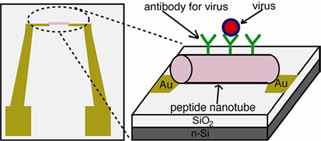
To develop robust and label-free viral sensors, a new detection platform where a pair of electrodes was bridged by antibody-coated peptide nanotubes was developed. Here, the nanotubes could concentrate targeted viruses by antibody on the nanotube surfaces via molecular recognition, and the size of the nanotube is perfectly fitted within the electric field line distribution for enabling the extremely sensitive impedimetric detection of viral particles.
Keywords: Peptide nanotube, Pathogen sensor, Virus, Self-assembly, Bionanotechnology
Due to the advancement of bottom-up nanofabrication, various nano-materials with superior physical properties have been applied as building blocks to assemble complex device configurations.[1–11] Among these nano-material building blocks, peptide nanotubes have been self-assembled into a variety of device geometries since their self-assembly is robust and locations to immobilize peptide nanotubes on substrates can be targeted with their biomolecular recognition.[12, 13] However, one of unexplored areas in the peptide nanotube-based devices is the lab-on-chip sensor. In this report, we examined the feasibility to assemble the peptide nanotube sensors in the simple chip geometry (Figure 1) which can electrically detect viruses with extremely low detection limit. There are a few distinctive features of the pathogen sensors utilizing peptide nanotubes. First, peptide nanotubes can incorporate any antibodies for viruses without losing the recognition function so that targeted viruses are selectively trapped on the peptide nanotube surfaces with strong affinity. Second, the shape and the dimension of peptide nanotube are ideal to detect the binding event with viruses because they match the electric field line distribution between a pair of electrodes (Figure 2-(c)), which maximizes the impedance signal from the virus binding to accomplish the low detection limit of viruses. Third, theses dielectric peptide nanotubes can be aligned between electrodes via dielectrophoresis easily to adapt flexible designs of virus sensing probes on the chips. These features make the peptide nanotube-based device an exceptionally sensitive sensor.
Figure 1.

A design of peptide nanotube-assembled pathogen sensor platform. The peptide nanotube incorporates virus-recognition elements on the nanotube surface.
Figure 2.

Fabrication of the peptide nanotube sensor platform and its label-free electric detection of viruses. (a) Peptide nanotubes are coated by antibody against targeted virus and injected onto the electrode-patterned platform while applying an AC field; the peptide nanotubes are trapped at the gap between adjacent electrodes by positive dielectrophoresis. (b) Peptide nanotubes bridging the electrodes bind viruses via biomolecular recognition. (c) The presence of dielectric bioparticles in this region where the electric field strength is at maximum results in a decrease of the capacitance between the electrodes. (d) Optical image of the peptide nanotube assembled at the gap between electrodes by positive dielectrophoresis (10 Hz, 5 V AC peak-to-peak potential). Scale bar = 10 μm. (e) TEM image of the anti-HSV-coated peptide nanotube after incubation in the sample containing HSV-2. Scale bar = 500 nm. (f) TEM image of the mouse IgG-coated peptide nanotube after incubation in the sample containing HSV-2. Scale bar = 500 nm.
The on-chip pathogen sensing platform (Figure 1) consists of a pair of electrodes separated by a micrometric gap that is bridged with peptide nanotubes. In this platform configuration, as a sample was injected to the chip, the binding event between the virus in the sample and its antibody on the peptide nanotube was detected by capacitance change between the electrodes. It should be noted that previously the capacitance and the impedance measurements were applied to detect micron-sized cells[14, 15] and recently the nanoscale capacitance probe was demonstrated to characterize the compositions of polymers and semiconductors,[16–19] however it has not been applied extensively to develop as pathogen nanosensors yet. Typically, the DC conductive probe was used to detect small biological molecules and viruses in the semiconductor nanowire-bridged sensing platform,[20–23] but here we applied the AC capacitance probe for the virus detection due to the non-conductive nature of the nanotubes, thus making the contact between the peptide nanotube and electrodes not as influential to the signal as for the conventional DC conductive probe, which is expected to increase the accuracy of the detection.
The peptide nanotubes applied for the sensor chip fabrication were self-assembled from peptide bolaamphiphile monomers and then coated by antibodies by the simple incubation process.[24–26] To assemble them into the device platform shown in Figure 1, the peptide nanotubes were addressed to the gap between a pair of electrodes by positive dielectrophoresis (Figure 2-(a),(b)).[27–29] The pathogen detection in this device configuration takes advantage of the difference in the dielectric properties between viral particles and water molecules. It has been well established that viral particles have lower dielectric constants as compared to water in accordance with their core-shell structure.[30] Hence, the binding of viruses to the peptide nanotubes is expected to decrease the permittivity of the surrounding of the nanotube medium, consequently decreasing the capacitance between the electrodes (Figure 2-(c)). We were able to detect the binding event of nanoscale viral particles to the nanotube by capacitance change because the peptide nanotube was placed at the gap between the electrodes where the path of the currents was the shortest and the electric field was the strongest. In this device configuration, the major role of the nanotube is to concentrate targeted viruses selectively by molecular recognition at this location. Here, impedimetric detection with the electrodes is most sensitive, and the dimension of peptide nanotube matches the electric field line distribution very well, therefore enhancing capacitance signals. To demonstrate the proof-of-concept of this fabrication process and detection scheme, we examined the label-free detection of herpes simplex virus type 2 (HSV-2) by the peptide nanotube-assembled sensor.
Figures 2-(a) – (c) illustrate the processes of the peptide nanotube-assembled platform fabrication and the virus detection. In the steps (a) and (b), the peptide nanotubes addressed to the gap between adjacent gold electrodes by positive dielectrophoresis (the procedure for the electrode fabrication is available in Supporting Information). Dielectrophoresis refers to the force on polarizable particles in a spatially non-uniform electric field, and when particles are pulled towards points of electric field maxima this phenomenon is termed positive dielectrophoresis.[31, 32] Figure 2-(d) shows a representing image of electrodes on the platform after a 10 Hz, 5 V peak-to-peak AC field was applied in the presence of the peptide nanotube solution. In this image, the peptide nanotube was placed at the gap between the electrodes where the electric field had the maximum strength, as expected from the positive dielectrophoresis process. This entrapment of the peptide nanotube took place at low frequency, in good agreement with previous reports on the dielectrophoretic focusing of other dielectric materials such as cells, and it indicates that an interfacial polarization process is responsible for this phenomenon.[33, 34] In the step (b) in Figure 2, HSV-2 in solution was bound to the anti-HSV-2 on the nanotube, as shown in Figure 2-(e). In this image, the viral particles were closely packed on the nanotube via biomolecular recognition. As a control experiment, when mouse IgG was coated on the nanotube instead of the anti-HSV-2, no interaction between the IgG nanotube and HSV-2 particles was observed in Figure 2-(f) since mouse IgG lacks the capability to specifically recognize the HSV-2. This control experiment indicates that the anti-HSV-2-coated nanotube is capable of selectively anchoring HSV-2 without noticeable nonspecific binding. Later, this mouse IgG-coated nanotube was used as a blank to rectify the net capacitance values of HSV-2 since it did not bind specifically HSV-2. The binding of HSV-2 to the peptide nanotube also confirms that anti-HSV-2 was certainly coated fully on the nanotube via the overnight incubation treatment.[35]
After all the peptide nanotube sensors were immersed in a BSA-PBS solution for 1 h to prevent nonspecific adsorption of the viruses to the chip surface, impedance spectra for the HSV-2 were taken by each peptide nanotube-immunosensor from 10 KHz to 1 MHz, 10 mV AC peak-to-peak potential in glycine buffer with an impedance analyzer. Figure 3-(a) shows impedance spectra obtained by the sensor with the anti-HSV-2-coated peptide nanotube before and after incubating HSV-2 in the concentration of 104 pfu/ml. The inset shows the simplified circuit model for the nanotube-based sensor in aqueous solution used to obtain capacitance values from measured impedance data (details for this circuit model are described in Supporting Information). In Figure 3-(a), at high frequencies the value of the impedance modulus shown by circles depended on the frequency and the phase angle shown by triangles was close to −90°, thus showing the typical behavior of a capacitor. It is noteworthy that the recognition of HSV-2 on the peptide nanotube increased the impedance in this region, as expected from a decrease in capacitance due to the inclusion of low permittivity materials at the gap between the electrodes. This outcome is consistent with the proposed transduction mechanism of the peptide nanotube-modified electrodes and shows the potential to apply the nanotube platform as a virus sensor.
Figure 3.

(a) Impedance spectra of peptide nanotube-assembled sensing platform. Hollow circles are impedance modulus values before incubating HSV-2, and filled circles are impedance modulus values after incubating HSV-2. Hollow triangles are phase angles before incubating HSV-2, and filled triangles are phase angles after incubating HSV-2. Impedance data was fitted to the equivalent electric circuit in the inset. Rc is the resistance of the contacts, Rsol is the resistance of the solution, and Csol is the capacitance of the solution, which is proportional to the permittivity of the solution. (b) Correlation between capacitance and the concentration of HSV-2 in the sample solution. ΔCsol is the corrected capacitance value by subtracting the blank measurement.
In order for the evaluation of this peptide nanotube platform for the HSV-2 detection, we plotted the capacitance versus concentration of HSV-2 in Figure 3-(b). The capacitance value for each viral concentration was obtained by fitting the impedance data to the equivalent circuit shown in the inset of Figure 3-(a) with the Zview2 software (Details about the equivalent circuit and the impedimetric analysis are available in Supporting Information).[36] For each point in the response curve of the sensor, the capacitance value of HSV-2 was corrected by subtracting the blank value obtained with the control nanotube platform, where the nanotube was coated with mouse IgG that did not bind HSV-2 as shown in Figure 2-(f). This correction is also useful to reduce the deice-by-device variation of capacitance measurements of viruses. The differential capacitance ΔC in Figure 3-(b) shows negative values because HSV-2 binding to the antibody of the peptide nanotube results in a net decrease in capacitance (i.e., net increase in impedance) with respect to the blank measurement. This is in accordance with the proposed transduction mechanism of a decrease in the permittivity of the solution due to the confinement of the virus in the region of electric field maximum induced by the interaction with the peptide nanotube. Figure 3-(b) shows that the capacitance change was detectable in the HSV-2 concentration range of 102 – 104 pfu/ml. The peptide nanotube platform integrated with electrical transducers has a better detection limit as compared to other label-free detection approaches based on optical transducers for similar viral strains,[37] and it supports our proposition that the peptide nanotube-based biosensors are well suited for the highly sensitive label-free detection of viruses.
In conclusion, the peptide nanotube sensor platform, which contains a pair of electrodes bridged by antibody-coated peptide nanotubes was developed by combining the top-down fabrication, photolithography of electrodes, and the bottom-up fabrication, dielectrophoretic self-assembly of the nanotubes. The binding event of virus and its antibody on the nanotube was detected by capacitance change between the electrodes. This label-free electrical detection on the peptide nanotube platform could detect HSV-2 with the concentration of 102 pfu/ml within 1 hr. This peptide nanotube chip can be easily scaled up by increasing the number of nanotubes and electrodes on the chip, thus enabling the multiplexed detection of viruses as peptide nanotubes coated by multiple antibodies are registered on the array platform. It should be noted that the specificity for this virus detection comes from the antibody recognition. In addition to the antibody specificity, the capacitance values of viruses measured by this peptide nanotube sensor could be used to verify and identify the virus binding. Recently, the difference of capacitance spectra between viruses was shown to be large enough to distinguish the virus strains.[35] Thus, in our sensor chip configuration the capacitance values of viruses can also be potentially used to reduce false-positive signals in complex samples. This hypothesis is currently investigated in the multiplex detection chip configuration.
Experimental Section
The peptide nanotubes, self-assembled from the bolaamphiphile peptide monomer, bis (N-α-amidoglycylglycine)-1,7-heptane dicarboxylate, were used as templates to immobilize antibodies on the nanotube surfaces.[38, 39] Previously, the surface of the peptide nanotube was engineered to incorporate a variety of biomolecules via hydrogen bonding,[12] and in the present work the peptide nanotube was coated by sheep polyclonal anti-HSV-2 (0.1 mg/ml, Abcam). After overnight incubation with anti-HSV-2, 10 μl of bovine serum albumin (BSA, 40 mg/ml) in PBS buffer was added to block uncoated sites on the nanotube surface and prevent nonspecific adsorption of viruses. Then, a 0.3 μl drop of the peptide nanotube solution was spotted onto the electrodes and a 10 Hz, 5V peak-to-peak potential AC field was applied to trap the nanotubes between the by the dielectrophoretic force and physicochemical interactions. To evaluate the detection performance of the viruses, a solution containing the HSV-2 (101 - 104 pfu/ml) was incubated with the sensor platform for 1 hr and then impedance spectra were taken from 10 KHz to 1 MHz, 10 mV AC peak-to-peak potential in glycine buffer (250 mM) with a SI 1260 SOLARTRON impedance analyzer. (more detailed procedures are in Supporting Information).
Supplementary Material
Acknowledgments
** This work for parts of the antibody nanotube synthesis and the surface alignment of the nanotubes was supported by the U.S. Department of Energy (DE-FG-02-01ER45935). The AC impedance measurements and the capacitance analysis of viruses were supported by the National Science Foundation (ECCS-0823902). Hunter College infrastructure is supported by the National Institutes of Health, the RCMI program (G12-RR-03037). E. Mendoza acknowledges the Ministerio de Ciencia y Tecnologia for the Ramon y Cajal contract. The microelectrodes were fabricated at MC2 Nanofabrication Laboratory, Chalmers University of Technology, Göteborg, Sweden and was financed by the FP6-Research Infrastructures program MC2ACCESS through Contract No: 026029.
Footnotes
Supporting information for this article is available on the WWW under http://www.angewandte.org or from the author.
References
- [1].Smith PA, Nordquist CD, Jackson TN, Mayer TS, Martin BR, Mbindyo J, Mallouk TE, Appl. Phys. Lett 2000, 77, 1399. [Google Scholar]
- [2].Lumsdon SO, Kaler EW, Velev OD, Langmuir 2004, 20, 2108. [DOI] [PubMed] [Google Scholar]
- [3].Hamers RJ, Beck JD, Eriksson MA, Li B, Marcus MS, Shang L, Simmons J, Streifer JA, Nanotechnology 2006, 17, 280. [Google Scholar]
- [4].Ryan KM, Mastroianni A, Stancil KA, Liu H, Alivisatos AP, Nano Lett. 2006, 6, 1479. [DOI] [PubMed] [Google Scholar]
- [5].Huang Y, Duan X, Cui Y, Lauhon LJ, Kim KH, Lieber CM, Science 2001, 294, 1313. [DOI] [PubMed] [Google Scholar]
- [6].Rao SG, Huang L, Setyawan W, Hong SH, Nature 2003, 425, 36. [DOI] [PubMed] [Google Scholar]
- [7].Liu SHT, J.B.H., Locklin J, Bao ZN, Small 2006, 2, 1448. [DOI] [PubMed] [Google Scholar]
- [8].Huang XMH, Caldwell R, Huang LM, Jun SC, Huang MY, Sfeir MY, O’Brien SP, Hone J, Nano Lett. 2005, 5, 1515. [DOI] [PubMed] [Google Scholar]
- [9].Yu GH, Cao AY, Lieber CM, Nature Nanotech. 2007, 2, 372. [DOI] [PubMed] [Google Scholar]
- [10].Lin CX, Ke YG, Liu Y, Mertig M, Gu J, Yan H, Angew. Chem. Intl. Ed 2007, 46, 6089. [DOI] [PMC free article] [PubMed] [Google Scholar]
- [11].Deng ZX, Mao CD, Angew. Chem. Intl. Ed 2004, 43, 4068. [DOI] [PubMed] [Google Scholar]
- [12].Gao X, Matsui H, Adv. Mater 2005, 17, 2037. [DOI] [PMC free article] [PubMed] [Google Scholar]
- [13].Reches M, Gazit E, Nature Nanotech. 2006, 1, 195. [DOI] [PubMed] [Google Scholar]
- [14].Sohn LL, Saleh OA, Facer GR, Beavis AJ, Allan RS, Notterman DA, Proc. Natl. Acad. Sci. USA 2000, 97, 10687. [DOI] [PMC free article] [PubMed] [Google Scholar]
- [15].Beck JD, Shang L, Li B, Marcus MS, Hamers RJ, Anal. Chem 2008, 80, 3757. [DOI] [PubMed] [Google Scholar]
- [16].Shao R, Kalinin SV, Bonnell DA, Appl. Phys. Lett 2003, 82, 1869. [Google Scholar]
- [17].Layson A, Gadad S, Teeters D, Electrochim. Acta 2003, 48, 2207. [Google Scholar]
- [18].Pingree LSC, Martin EF, Shull KR, Hersam MC, IEEE Trans. Nanotech 2005, 4, 255. [Google Scholar]
- [19].Hilton AM, Lynch BP, Simpson GJ, Anal. Chem 2005, 77, 8008. [DOI] [PubMed] [Google Scholar]
- [20].Patolsky F, Zheng GF, Hayden O, Lakadamyali M, Zhuang XW, Lieber CM, Proc. Natl. Acad. Sci. USA 2004, 101, 14017. [DOI] [PMC free article] [PubMed] [Google Scholar]
- [21].Zhang YB, Kanungo M, Ho AJ, Freimuth P, van der Lelie D, Chen M, Khamis SM, Datta SS, Johnson ATC, Misewich JA, Wong SS, Nano Lett. 2007, 7, 3086. [DOI] [PubMed] [Google Scholar]
- [22].Chen RJ, Bangsaruntip S, Drouvalakis KA, Kam NWS, Shim M, Li YM, Kim W, Utz PJ, Dai HJ, Proc. Natl. Acad. Sci. USA 2003, 100, 4984. [DOI] [PMC free article] [PubMed] [Google Scholar]
- [23].Park SJ, Taton TA, Mirkin CA, Science 2002, 295, 1503. [DOI] [PubMed] [Google Scholar]
- [24].Nuraje N, Banerjee IA, MacCuspie RI, Yu L, Matsui H, J. Am. Chem. Soc 2004, 126, 8088. [DOI] [PubMed] [Google Scholar]
- [25].Zhao Z, Banerjee IA, Matsui H, J. Am. Chem. Soc 2005, 127, 8930. [DOI] [PMC free article] [PubMed] [Google Scholar]
- [26].Zhao Z, Matsui H, Small 2007, 3, 1390. [DOI] [PMC free article] [PubMed] [Google Scholar]
- [27].Bhatt KH, Grego S, Velev OD, Langmuir 2005, 21, 6603. [DOI] [PubMed] [Google Scholar]
- [28].Park K, Akin D, Bashir R, Biomed. Microdevices 2007, 9, 877. [DOI] [PubMed] [Google Scholar]
- [29].Docoslis A, Espinoza LAT, Zhang BB, Cheng LL, Israel BA, Alexandridis P, Abbott NL, Langmuir 2007, 23, 3840. [DOI] [PubMed] [Google Scholar]
- [30].Hughes MP, Morgan H, Rixon FJ, Biochim. Biophys. Acta, Gen. Subj 2002, 1571, 1. [DOI] [PubMed] [Google Scholar]
- [31].Koh SJ, Nanoscale Res. Lett 2007, 2, 519. [DOI] [PMC free article] [PubMed] [Google Scholar]
- [32].Lapizco-Encinas BH, Rito-Palomares M, Electrophoresis 2007, 28, 4521. [DOI] [PubMed] [Google Scholar]
- [33].Arnold WM, Schwan HP, Zimmermann U, J. Phys. Chem. B 1987, 91, 5093. [Google Scholar]
- [34].Green NG, Morgan H, J. Phys. Chem. B 1999, 103, 41. [Google Scholar]
- [35].MacCuspie RI, Banerjee IA, Pejoux C, Gummalla S, Mostowski HS, Krause PR, Matsui H, Soft Matter 2008, 4, 833. [DOI] [PMC free article] [PubMed] [Google Scholar]
- [36].de la Rica R, Fernandez-Sanchez C, Baldi A, Electrochem. Commun 2006, 8, 1239. [Google Scholar]
- [37].Ymeti A, Greve J, Lambeck PV, Wink T, van Hovell SWFM, Beumer TAM, Wijn RR, Heideman RG, Subramaniam V, Kanger JS, Nano Lett 2007, 7, 394. [DOI] [PubMed] [Google Scholar]
- [38].Kogiso M, Ohnishi S, Yase K, Masuda M, Shimizu T, Langmuir 1998, 14, 4978. [Google Scholar]
- [39].Matsui H, Gologan B, J. Phys. Chem. B 2000, 104, 3383. [Google Scholar]
Associated Data
This section collects any data citations, data availability statements, or supplementary materials included in this article.