Abstract
MRI-conditional robotic platforms have proved to be an effective approach for image guided interventions. In this study, a computer-assisted, pneumatically-actuated robot was designed, built, and tested for MRI-guided prostate cancer focal laser ablation (FLA). The robotic manipulator provides two active planar degrees of freedom (DoFs) by using a customized CoreXY frame, and one passive rotational DoF. A remote insertion mechanism improves the surgical workflow by keeping the patients inside the scanner during needle insertion. The robotic manipulator was tested in a 3T MR scanner to evaluate its MR compliance, and the results demonstrated that the signal-to-noise ratio (SNR) variation was less than 8%. The in-scanner template positioning accuracy test demonstrated that the manipulator achieves high targeting accuracy with a mean error of 0.46 mm and a standard deviation of 0.25mm. Phantom studies have shown that the needle insertion accuracy of the manipulator is within 2mm (Mean = 1.7mm, StD = 0.2mm).
Index Terms: MRI, Focal Laser Ablation, Prostate Cancer, Image Guided Therapy, Robot
I. Introduction
Prostate cancer is the most common non-skin male cancer and the second leading cause of cancer death in men in the United States; it accounts for one quarter of new cancer diagnoses in men. An estimated 220,800 new cases were diagnosed and almost 27,540 men were expected to die due to prostate cancer in 2015 [1]. Current trends in prostate cancer treatment include radical prostatectomy and minimally invasive procedures under image guidance. Radical prostatectomy is performed by removing part or all of the prostate gland and surrounding tissue. However, clinical data suggests that prostatectomy over-treats the cancer, leaving negative side effects such as incontinence and sexual dysfunction [2]. For patients with early-stage prostate cancer, minimally invasive interventions are an attractive option due to the benefits of shorter hospitalization, reduced recovery time, and fewer in-patient procedures with less complication.
Focal laser ablation (FLA) is a minimally invasive treatment method that efficiently treats the target tumor while avoiding over-treatment of neighboring tissues [3]. Focal ablation is an evolving technique that delivers heat energy to the region of interest for tissue ablation. Ablation energy sources consist of high-intensity focused ultrasound (HIFU) [4], photodynamic therapy [5], cryotherapy [6], and laser energy [7]. The laser ablation technique has the advantages of MRI-compatibility, flexible energy delivery, and confluent tissue destruction [8]. MRI produces excellent anatomic resolution of soft tissue, and MRI-guided FLA is currently the most accurate method for delivering thermal energy to a target position. In addition, MR thermometry could be used during MRI-guided FLA to accurately monitor the temperature of tissue in and around the ablation zone, enabling intraoperative evaluation of the surgical outcome [9]. The wavelengths of commercially available laser fibers are 805 nm (Diomed Inc., MA) [10], 830 nm (Indigo, Inc., OH) [11], and 980 nm (Visualase, Inc., TX) [9].
To perform MRI-guided FLA, a grid template is applied to guide the needle and laser fiber to the targeted location. However, the distance between adjacent holes on the template is 5 mm, which limits needle insertion resolution. In addition, the template only provides two planar degrees of freedom (DoFs), but the angular DoF is important in clinical applications since it allows physicians to avoid penetrating normal tissue, such as the pubic arch, and causing nerve bundle interference [12]. To address the limitations of the current FLA approach, Cepek et al. reported a manually operated mechanism for MRI-guided FLA [13]. Physicians control the position and orientation of the guide template for desired needle trajectory alignment. The in vivo test showed that the median needle insertion accuracy was 3.5mm, and the phantom study showed it to be 2.64mm [13, 14]. However, accurately controlling and planning the desired needle trajectory requires time-consuming training and higher practice costs for physicians.
An MRI-guided robotic needle insertion navigation device is promising since it operates safely, accurately, and efficiently compared to the manual version. According to the standards of American Society for Testing and Materials (ASTM F2503), an item can be classified as MRI-safe, MRI-conditional, or MRI-unsafe based on its effect on magnetic force, torque, RF heating, image artefact, induced voltages, electromagnetic compatibility, etc. [15]. MRI-safe is defined as no known hazards in the entire MR environment; MRI-conditional is defined as no known hazards in a specific environment; MRI-unsafe is defined as known hazards in the entire MR environment [16]. Therefore, in order to guarantee safety throughout the surgery, the robot should be fabricated with MRI-conditional or MRI-safe materials. To date, there have been several reported MRI-conditional robotic systems for prostate interventions. Krieger et al. developed a 6-DoF transrectal robot with a hybrid fiducial tracking method [17]. Su et al. designed a 6-DoF, piezoelectric motor-driven robot for transperineal prostate interventions [18]. Eslami et al. reported their design of a parallel robotic needle insertion platform with piezo actuators [19]. The majority of these MRI-conditional prostate robots are driven by piezo actuators, which could adversely affect image quality. According to the work done by Wendt et al. [20], the piezoelectric motor could reduce the SNR by up to 50% even when not powered.
A pneumatic motor can provide MRI-conditional actuation since its working principle is electromagnetically decoupled from the MR scanner. Pneumatic actuators use compressed air as an energy source, which is a standard configuration in the MR room. A pneumatic motor can be fabricated with MRI-conditional materials using 3D printing technology. Stoianovici et al. developed the first MRI-conditional pneumatic stepper motor in the world [21], and this motor has been used in MRI compatible robots for prostate intervention. Following the pioneering attempt in MRI-conditional stepper motors, different versions were developed by Bosboom, Sajima, Chen, and Comber in the past several years: Bosboom et al. designed a pneumatic stepper motor for Soterial Medical in 2010 with tunable step size and accuracy by sequentially pushing the conical piston tip to the rotor holes [22]; Sajima et al. proposed an MRI-safe stepper motor in 2012 with a similar mechanism to create the step rotation of 4.29 degrees [23]; Chen et al. developed two MRI-conditional stepper motors in 2014 and 2015 [24, 25]; and Comber et al. developed the linear and rotatory stepping mechanism controlled with the sliding mode algorithm [26]. The major limitation of pneumatic stepper motors is the low operation speed. Speed is limited by its working principle, which relies on the sequentially pressurized air supply instead of continuous air supply. Another drawback of existing pneumatic stepper motors is the complex working principle, mastered only by a few research groups. To date, pneumatic motors have been applied in several MRI-conditional robotic devices. Besides the pneumatically driven prostate robot developed by Stoianovici, Fischer et al. proposed a 6-DoF parallel robotic platform with pneumatic cylinder actuator for transperineal prostate needle placement in 2008 [27]. Yakar et al. developed a 5-DoF pneumatically actuated robotic platform for biopsy guidance [28] in 2011. However, a remote needle insertion capability was not incorporated in these robots. Based on the consultations with our contacts from the National Institute of Health (NIH), clinicians prefer to perform manual needle insertion to ensure surgical safety.
In this study, we propose a robotic manipulator with two active planar DoFs, one passive angular DoF, and remote insertion capability. It is an inherently MRI-conditional manipulator, as it is driven by two custom designed pneumatic vane motors. The working principle and encoding method of the MRI-conditional pneumatic motor are presented. The manipulator’s controls are integrated with the MR imaging and planning interface (OncoNav, National Institutes of Health, USA) to provide intraoperative manipulation guidance and evaluation of surgical outcome. Our phantom study showed that the proposed manipulator is able to reach submillimeter targeting accuracy with minimal image distortion on the ROI.
II. Methods and Materials
A. Manipulator Design Overview
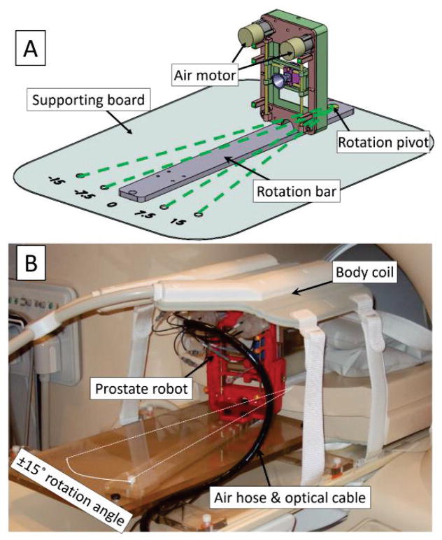
The goal of developing an MRI-conditional robotic system necessarily imposed several requirements for patient safety and preserving image quality. As with all MRI-conditional robotic systems, ferromagnetic materials were entirely avoided. The majority of the components were 3D printed using plastic materials (ABS), with the linear guidance rod fabricated from brass. Fig. 1 shows the proposed pneumatically driven prostate manipulator with overall dimensions of 130mm × 180mm lying on the top of a supporting board. The end effector workspace to cover the prostate was determined to be approximately 50mm × 50mm in the transverse plane of the patient in a supine position. In order to compensate for variations in prostate height above the gantry among different patients, the workspace was extended an additional 40mm vertically.
Fig. 1.
A: 3D assembly design of the prostate manipulator. The proposed prostate manipulator rides on top of the rotation bar, which can be rotated around a pivot point on the supporting board. The four dashed green lines show the ±7.5° and ±15° rotation angle with respect to the B0 field; B: Prostate manipulator assembly placed on the MR table covered by a body coil.
The manipulator is mounted on a rotation bar capable of being manually rotated ±7.5° and ±15° Fig. 1), relative to the B0 field (inferior-superior direction). The rotational DoF is achieved by manually fixing the rotation bar to predefined positions on the supporting board in the trajectory planning step of the proposed workflow. This rotational DoF provides alternatives in scenarios where a straight-shot needle trajectory intersects with a neurovascular bundle and/or the urethra. Since the rotation is mechanically fixed to predefined positions, the rotational feedback is not needed in the design. In addition, the fixed design precludes the application of a rotational encoder, which ensures the MR compatibility and simplicity of operation.
B. Manipulator Working Principle
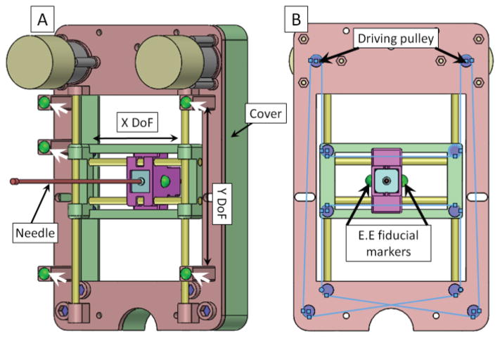
A compact design based on the CoreXY system [29] was chosen as a solution to meet the design requirements (Fig. 2). CoreXY is a parallel kinematic platform that provides Cartesian motion while keeping the motors stationary to achieve high accelerations. The custom-designed CoreXY system allows both motors to be mounted on the anterior direction of the manipulator frame, reducing the number of moving parts, avoiding the interference between the air hose and the patient’s leg, and allowing a more compact design while maintaining the same workspace of the end effector.
Fig. 2.
A: Back view of the manipulator assembly. White arrows show the gadolinium fiducial marker (green balls) positions on the manipulator frame. Four yellow rods represent the linear guiding rods in the X/Y direction and the manipulator has two translational DoFs. B: Front view of the manipulator. The blue lines show a schematic diagram of the belt on the manipulator. The driving pulleys are coupled to the output shaft of the two air motors. Driven pulleys are located on the manipulator frame. Two manipulator end effector (E.E) fiducial markers are placed on both sides of the manipulator movable template to localize the end effector’s position in the MRI coordinate frame.
There are ten sets of pulleys in the proposed mechanism, two of which are attached to the motor output shaft as the driving pulleys. The rest are located on the manipulator frame. All the pulleys are fabricated with a 3D printing technique to ensure the MR-compatibility of the proposed device. An MXL Series Timing Belt (item number: 7887K35 McMaster, USA) is applied to transfer motor shaft rotational motion to end effector translational motion. The CoreXY system utilizes two bi-directional controllable motors to provide motion of the needle template. The relationship between motor rotation and end effector position is mathematically defined as:
| (1) |
where ΔA and ΔB are the motor rotational distances while ΔX and ΔY are the end effector positions, nA and nB are the number of motor rotations, N is the gearbox transmission ratio, and r is the radius of the pulley attached to the output shaft of the gearbox [29]. In this study, the pneumatic actuator is based on our prior pneumatic vane motor design by adding an MRI-conditional optical encoding technique [30, 31]. The motor is controlled via the PID algorithm with the end effector dead band of 0.3mm, which can be regarded as an acceptable range after detailed discussions with clinicians.
We use the point-based registration method in this study to register the manipulator coordinate frame to the MR scanner coordinate system [32]. Five gadolinium fiducial markers (Beekley, USA) are placed on the manipulator at pre-defined positions. The homogeneous transformation between these two frames can be expressed in the following equation
| (2) |
where Probot is the marker position in the manipulator frame, PMRI is the marker position in the MRI scanner coordinate frame, and R and d are the rotation matrix and translation matrix, respectively. The fiducial markers are located 50mm away from the manipulator frame in the inferior-superior direction to avoid the inhomogeneous magnetic area caused by the brass rods.
C. Pneumatic Motor Design
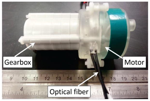
Fig. 3 shows the pneumatic actuator prototype in a compact construction, which contains the pneumatic motor and gearbox. The actuator unit was 3D printed with overall dimensions of ∅44mm × 40mm. A planetary gearbox (Tamiya, Japan) was coupled to the motor to gear down the output speed and increase the torque. The dimensions of the actuator unit and planetary gearbox can be further minimized, allowing the designer to tailor the surgical robot to meet different operational condition requirements.
Fig. 3.
Prototype of the pneumatic motor coupled with a 2000:1 gearbox.
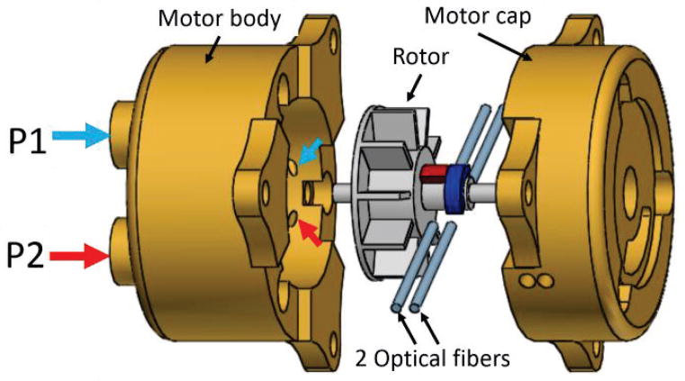
To ensure the MR-compatibility of our proposed pneumatic actuation approach, the actuator unit is fabricated with MR compatible material (GPCL03, formlabs, USA). The mechanical property of this material can guarantee the mechanical strength, durability, and reliability of the motor. The optical fiber used in the motor is made of silica and plastic, which have been shown to be MR compatible [33]. The schematic diagram of the pneumatic motor’s working principle can be seen in Fig. 4.
Fig. 4.
Exploded view of the pneumatic motor, which consists of motor body, rotor, 2 sets of optical fibers, and motor cap. P1 and P2 are the air inlets; small blue and red arrows show the air outlet corresponding to each inlet.
The pneumatic actuator consists of four major components: motor body, rotor, motor cap, and optical fibers. We use three plastic threaded rods to connect the motor body and motor cap together. P1 and P2 are the air inlets which can be supplied with pressurized air. The air outlets are represented by small arrows in Fig. 4. There are three pairs of outlets separated evenly by 120° around the inner surface of the motor body. When air inlet P1 is supplied with pressurized air, the corresponding pneumatic flow coming from the air outlets drives the rotor rotation in the clockwise direction; counterclockwise rotation can be achieved by supplying air inlet P2 with pressurized air.
D. MRI-conditional Encoding
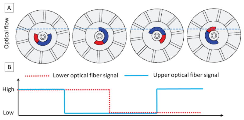
In order to track the motor operation speed and position, we employ a novel encoding technique in our motor design. The operation principle of the encoding method can be seen in Fig. 5. Due to the rotatory motion of the rotor, the lower/upper channels of optical fibers have two statuses: open (optical signal passing from the sender fiber to the receiver fiber) and closed (optical signal blocked by the blue/red segments of the rotor in Fig. 4). The light intensity transmitted from the sender fibers to the receiver fibers can be detected with a photo-resistor. The photo-resister and its associated electronics, which are located in the control room, transfer the optical signal to the electrical transistor–transistor logic (TTL) signal. Based on the counts and frequency of TTL signals, we can track the motor’s position as well as its speed. We use two pairs of the optical fibers in our design so as to track motor rotation direction automatically. Monitoring the motor rotation direction is achieved by detecting the phase of the two channels. If the upper channel leads the lower channel, then the motor is rotating in the clockwise direction; if the lower channel leads the upper channel, then the motor is rotating in the counterclockwise direction. In Fig. 5A, the sequence can be summarized as follows: both channels open, upper channel closed and lower channel open, both channels closed, upper channel open and lower channel closed. The logic flow of this sequence can be seen in Fig. 5B.
Fig. 5.
Schematic diagram of the encoding method. A: four different scenarios when light passes through or is blocked by the rotor. The dashed blue line shows the optical flow, which can be blocked by the blue/red segments of the rotor shaft. B: optical signal detected by the photo-resister transferred to a logic signal.
E. Remote Insertion Mechanism
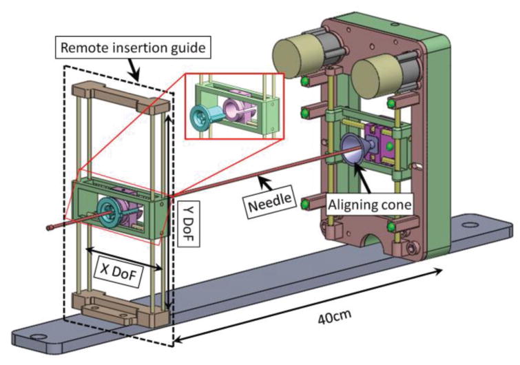
In this study, the needle for MR-guided FLA was inserted remotely by the surgeon to avoid removing patients from the MR bore (Fig. 6). Two primary components enabled this methodology: a remote insertion guide and an aligning cone at the robotic manipulator. The remote insertion guide has the same workspace as the robotic manipulator and is located in a parallel plane with respect to the manipulator. A removable core with a small diameter is located on the remote insertion guide for needle insertion guidance. The core consists of two passive translational DoFs, allowing the surgeon to manually align the core with respect to the end effector of the robotic manipulator. Once the remote insertion guide is aligned, the surgeon inserts the trocar or needle through the core towards the aligning cone. The alignment cone located on the manipulator corrects any errors caused by the distance between the manipulator and the remote insertion guide by “catching” the inserted instrument and guiding it into the end effector of the manipulator. In this way, the 60cm titanium diamond-tip needle used for the initial skin puncture can be maneuvered from outside the MRI bore.
Fig. 6.
Assembly view of the remote insertion mechanism with the prostate manipulator. The remote insertion guide is located approximately 40cm away from the manipulator. The exploded view shows that removable core (green color in the exploded view, OD = 15mm, ID = 2.5mm) can be removed for the cooling catheter extension arm guidance.
III. Results and Discussion
A. Robotic FLA Workflow Evaluation
The envisioned clinical workflow lasts for 75 minutes, as broken down in Table 1. The workflow consists of 5 major steps: preoperative preparation, MRI-manipulator coordinate registration, trajectory planning, needle targeting, and procedural outcome verification. In the current workflow, steps 6–8 are the manipulator movement, and trocar and catheter insertions, which account for 15 minutes out of 75 minutes. Once the surgeon is familiar with the clinical workflow, steps 6–8 can be reduced to around 5 minutes total. The MRI scans (steps 9–10) can be further reduced to ~5 minutes total for single-slice scans with reduced field of view (FOV). Steps 6–10 are specified by our interventional radiologists at this stage of development for post-ablation evaluation, and those steps can be further optimized. The efficacy of the robotic-assisted approach will be more obvious when multiple ablation targets are needed since steps 1–5 do not need to be repeated when the patient is in the same position.
Table 1.
Designed Clinical Workflow
| Step | Description | Time |
|---|---|---|
| 1. System initialization | Physical setup of manipulator and system | 10 min |
| 2. Patient positioning | Aligning position of subject in MRI | 10 min |
| 3. Localization scan | Initial scan to determine target location | 5 min |
| 4. High resolution scan & registration | High-resolution scans of target anatomy and manipulator fiducials | 20 min |
| 5. Trajectory planning | Ablation path planning | 5 min |
| 6. Manipulator targeting | Aligning manipulator guide with the target | 5 min. |
| 7. Trocar insertion | Inserting trocar into patient | 5 min |
| 8. Catheter insertion | Removal of trocar, and insertion of catheter | 5 min |
| 9. Confirmation scan | Confirming catheter location | 5 min |
| 10. FLA | Laser ablation and temperature monitoring | 5 min |
| 11. Repeat 6 – 10 | For multiple ablation targets | TBD |
| Total | 75 min |
B. MRI Compatibility Evaluation
Empirical validation of the manipulator’s ability to operate without introducing noise to MR images was accomplished by taking MR images of a phantom filled with a CuSO4 solution under four conditions: control image, manipulator introduced, manipulator powered at rest, and manipulator powered in motion. The SNR was calculated using the following method,
| (3) |
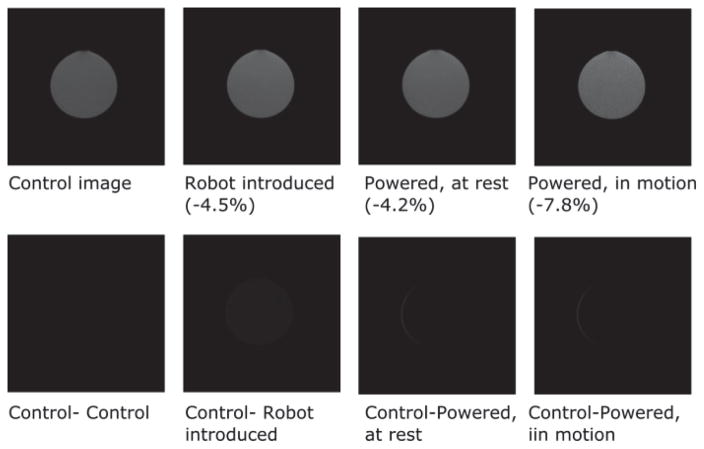
where μ1is the mean value within the 40×40 pixel region at the center of the image, and σ2 is the standard deviation of the 40×40 pixel region at the corner of the image. In the SNR test, the phantom bottle was placed at the isocenter of the MRI scanner and the robot was placed in the inferior direction. The distance between the robot end effector and the middle plane of phantom bottle is 20cm. The phantom MR image was obtained with the T2-weighted standard prostate imaging protocol: 28cm FOV, 3mm slice, TE = 90ms, TR = 5600ms. From Fig. 7, the maximum SNR variation was <8% in all cases, thus falling within an acceptable range for devices used inside MRI scanners [34]. Furthermore, subtracting the control image from the images obtained in the other three conditions demonstrates that the manipulator generates minimal image distortion of the phantom bottle image on ROI.
Fig. 7.
T2-weighted MR image of the phantom obtained with the 3T Philips MR scanner. Upper row: MR images of a bottle phantom obtained under four conditions. The maximum SNR reduction occurred when the manipulator was powered in motion, and was 7.8% compared to the control image. Lower row: subtracted control image for the evaluation of image distortion. The maximum thickness of the sliver on the bottom right two images is 1.1mm.
C. Template Positioning Accuracy Test
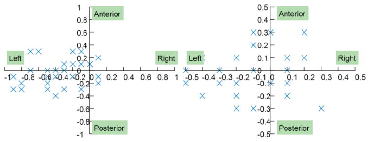
The manipulator’s accuracy in open air was tested by automatically moving the needle template to the desired position inside the scanner. Accuracy was evaluated by two metrics: the real error and the calculated error. The real error was measured by calculating the distance between the desired position and final position of the end effector. The calculated error is the difference between the desired position and the final position as reported by the control interface after automatic control. The final position of the end effector was obtained by calibrating the end effector fiducial markers’ positions in the MR images. Fig. 8 shows the error distributions of the manipulator; the targeting trial was conducted in 32 random positions throughout the manipulator workspace to ensure the experiment was statistically significant. The manipulator had a submillimeter real error, with a mean value of 0.46mm and a standard deviation of 0.25mm. The calculated error was smaller than the real error, with a mean value of 0.29mm and a standard deviation of 0.12mm. The main reason for this difference is that the calculated error is based solely on the dead band of the automatic control algorithm. However, the real error is more complicated since it can be affected by the controller’s performance, the backlash of the gearbox, the friction between the driving belt and the pulley, MR scanner-robot frame coordinate registration, and image registration.
Fig. 8.
Error distribution of the prostate manipulator. A: real error; B: calculated error.
D. Needle Insertion Accuracy Test
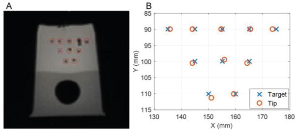
The needle insertion accuracy tests were carried out by inserting a needle into a prostate phantom. We chose a commercially available anatomical prostate phantom (CIRS, VA, USA) for accuracy analysis since it has been widely used for prostate robot accuracy evaluation. The insertion accuracy test allows the physician to simulate clinical FLA situations under MR guidance. The needle insertion error in the transverse plane (n=10) had a mean of 0.9 mm and a standard deviation of 0.4 mm, and along the insertion axis a mean of 1.9 mm and a standard deviation of 2.7 mm (Fig. 9). The larger along insertion axis error was caused by the image slice thickness (3.5mm) and the lack of practice in the proposed remote insertion mechanism. Tissue deformation also contributed to error along the insertion axis.
Fig. 9.
A: MR image of needle insertion results; B: Chart of targets and needle tip positions.
E. Phantom Study of Robotic FLA
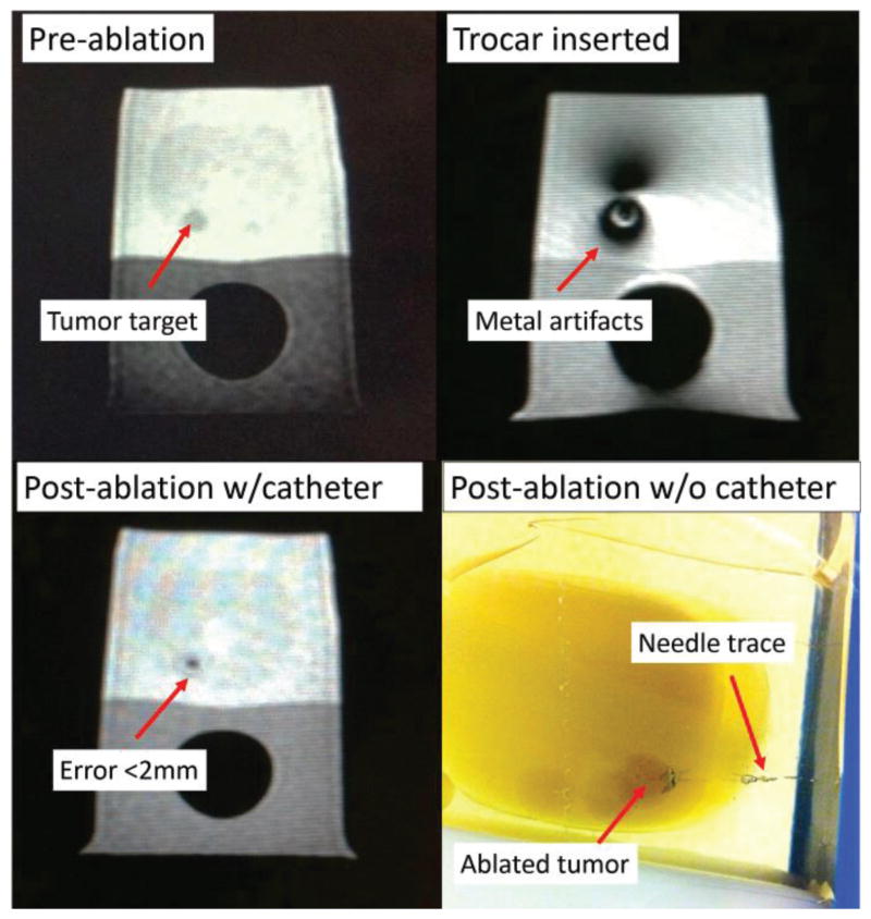
Robotic system efficacy tests were performed by navigating the needle to anatomical prostate phantoms with physical tumors (n=5) (Fig. 10). The MRI-guided FLA setup consists of a 3T MRI scanner (Achieva, Philips Healthcare, Netherlands), a navigation graphical user interface (OncoNav, the National Institutes of Health, USA), a laser fiber of 980nm wavelength with a cooling catheter (Medtronic, USA) [35], and the proposed manipulator. The temperature map can be calculated by using the proton resonance frequency shift (PRFS) method [36], which can be described in the following equation
Fig. 10.
MR images of the prostate phantom throughout FLA. The targeting error was less than 2mm.
| (4) |
where ϒ is the proton gyromagnetic ratio, α is the PRF change coefficient, B0 is the MRI field strength and TE is the echo time. All these parameters are constant values for a specific imaging sequence and scanner. ∅(t) is the current image phase and ∅0 is the reference image phase at a known temperature which serves as a baseline image. Each ablation took approximately 60 seconds with the maximum ablation temperature of 65°C. Prior to ablation, the needle was inserted manually through the designed setup to the target region and insertion accuracy of the needle relative to the designated target point was within 2mm (Mean = 1.7mm, Standard Deviation = 0.2mm). Analysis of the ablated regions demonstrated that 100% of the tumor volume was treated in each case, with <20% of tissue ablated outside the tumor, which were acceptable results for the FLA according to the feedback of our clinicians.
IV. Conclusion
In this study, we have proposed a motorized, compact manipulator with two active DoFs and one passive DoF that can guide the needle in the transverse plane with submillimeter accuracy. The proposed remote insertion feature optimizes the workflow by eliminating the need for moving patients in and out of the gantry, without sacrificing the physician’s comfort or targeting accuracy. The manipulator was tested in a 3T MR scanner and the results showed that the maximum SNR variance was less than 8%, which is within an acceptable range for MR compatible mechatronics. The manipulator generates minimal image distortion of the phantom bottle image (maximum thickness = 1.1mm) on ROI. Thirty-two trials were performed to evaluate the manipulator’s template positioning accuracy and the results showed that the manipulator achieved submillimeter accuracy (Mean = 0.46mm, StD = 0.25mm). Needle positioning accuracy was tested by a phantom study of the proposed robotic setup, and it showed that the targeting error was less than 2mm. This error is below the clinically acceptable error for prostate needle placement procedures [37].
Future work will focus on quantitative evaluation of the error source of the manipulator. The MR active tracking technique will be integrated with the proposed hardware to provide real-time guidance for needle insertion [38, 39]. In addition, animal trials will be performed to evaluate the proposed robotic setup.
Acknowledgments
This study was supported in part by the NIH Bench-to-Bedside Award, NIH Center for Interventional Oncology Grant, NSF I-Corps Team Grant (1617340), UGA-AU Inter-Institutional Seed Funding, American Society for Quality Dr. Richard J. Schlesinger Grant, PHS Grant UL1TR000454 from the Clinical and Translational Science Award Program, NIH National Center for Advancing Translational Sciences. NIH does not endorse or recommend any commercial products, processes, or services. The views and opinions of authors expressed herein do not necessarily state or reflect those of the U.S. Government nor does it constitute policy, endorsement or recommendation by the U.S. Government or National Institutes of Health (NIH). Please reference U.S. Code of Federal Regulations or U.S. Food and Drug Administration for further information.
Contributor Information
Yue Chen, College of Engineering, The University of Georgia, Athens, GA, 30605, USA.
Alexander Squires, College of Engineering, The University of Georgia, Athens, GA, 30605, USA.
Reza Seifabadi, Center for Interventional Oncology, Department of Radiology and Imaging Sciences, National Institutes of Health, Bethesda, MD, 20892, USA.
Sheng Xu, Center for Interventional Oncology, Department of Radiology and Imaging Sciences, National Institutes of Health, Bethesda, MD, 20892, USA.
Harsh Agrawal, Philips Research North America, Briarcliff, NY, 10510, USA.
Marcelino Bernardo, Center for Interventional Oncology, Department of Radiology and Imaging Sciences, National Institutes of Health, Bethesda, MD, 20892, USA.
Peter Pinto, Center for Interventional Oncology, Department of Radiology and Imaging Sciences, National Institutes of Health, Bethesda, MD, 20892, USA.
Peter Choyke, Center for Interventional Oncology, Department of Radiology and Imaging Sciences, National Institutes of Health, Bethesda, MD, 20892, USA.
Bradford Wood, Center for Interventional Oncology, Department of Radiology and Imaging Sciences, National Institutes of Health, Bethesda, MD, 20892, USA.
Zion Tsz Ho Tse, College of Engineering, The University of Georgia, Athens, GA, 30605, USA.
V. References
- 1.Siegel RL, Miller KD, Jemal A. Cancer statistics, 2015. CA: a cancer journal for clinicians. 2015;65:5–29. doi: 10.3322/caac.21254. [DOI] [PubMed] [Google Scholar]
- 2.Levinson AW, Lavery HJ, Ward NT, Su LM, Pavlovich CP. Is a return to baseline sexual function possible? An analysis of sexual function outcomes following laparoscopic radical prostatectomy. World Journal of Urology. 2011;29:29–34. doi: 10.1007/s00345-010-0616-5. [DOI] [PubMed] [Google Scholar]
- 3.Lindner U, Lawrentschuk N, Weersink RA, Davidson SR, Raz O, Hlasny E, Langer DL, Gertner MR, Van der Kwast T, Haider MA. Focal laser ablation for prostate cancer followed by radical prostatectomy: validation of focal therapy and imaging accuracy. European Urology. 2010;57:1111–1114. doi: 10.1016/j.eururo.2010.03.008. [DOI] [PubMed] [Google Scholar]
- 4.Ahmed HU, Moore C, Emberton M. Minimally-invasive technologies in uro-oncology: the role of cryotherapy, HIFU and photodynamic therapy in whole gland and focal therapy of localised prostate cancer. Surgical oncology. 2009;18:219–232. doi: 10.1016/j.suronc.2009.02.002. [DOI] [PubMed] [Google Scholar]
- 5.Arumainayagam N, Moore C, Ahmed HU, Emberton M. Photodynamic therapy for focal ablation of the prostate. World journal of urology. 2010;28:571–576. doi: 10.1007/s00345-010-0554-2. [DOI] [PubMed] [Google Scholar]
- 6.Bahn D, de Castro Abreu AL, Gill IS, Hung AJ, Silverman P, Gross ME, Lieskovsky G, Ukimura O. Focal cryotherapy for clinically unilateral, low-intermediate risk prostate cancer in 73 men with a median follow-up of 3.7 years. European urology. 2012;62:55–63. doi: 10.1016/j.eururo.2012.03.006. [DOI] [PubMed] [Google Scholar]
- 7.Oto A, Sethi I, Karczmar G, McNichols R, Ivancevic MK, Stadler WM, Watson S, Eggener S. MR imaging–guided focal laser ablation for prostate cancer: phase I trial. Radiology. 2013;267:932–940. doi: 10.1148/radiol.13121652. [DOI] [PubMed] [Google Scholar]
- 8.Lindner U, Trachtenberg J, Lawrentschuk N. Focal therapy in prostate cancer: modalities, findings and future considerations. Nature Reviews Urology. 2010;7:562–571. doi: 10.1038/nrurol.2010.142. [DOI] [PubMed] [Google Scholar]
- 9.Raz O, Haider MA, Davidson SR, Lindner U, Hlasny E, Weersink R, Gertner MR, Kucharcyzk W, McCluskey SA, Trachtenberg J. Real-time magnetic resonance imaging–guided focal laser therapy in patients with low-risk prostate cancer. European urology. 2010;58:173–177. doi: 10.1016/j.eururo.2010.03.006. [DOI] [PubMed] [Google Scholar]
- 10.Amin Z, Lees W, Bown S. Interstitial laser photocoagulation for the treatment of prostatic cancer. The British journal of radiology. 1993;66:1044–1047. doi: 10.1259/0007-1285-66-791-1044. [DOI] [PubMed] [Google Scholar]
- 11.Atri M, Gertner MR, Haider MA, Weersink RA, Trachtenberg J. Contrast-enhanced ultrasonography for real-time monitoring of interstitial laser thermal therapy in the focal treatment of prostate cancer. Canadian Urological Association Journal. 2009;3:125–30. doi: 10.5489/cuaj.1044. [DOI] [PMC free article] [PubMed] [Google Scholar]
- 12.Seifabadi R, Song SE, Krieger A, Cho NB, Tokuda J, Fichtinger G, Iordachita I. Robotic system for MRI-guided prostate biopsy: feasibility of teleoperated needle insertion and ex vivo phantom study. International journal of computer assisted radiology and surgery. 2012;7:181–190. doi: 10.1007/s11548-011-0598-9. [DOI] [PMC free article] [PubMed] [Google Scholar]
- 13.Cepek J, Lindner U, Ghai S, Louis AS, Davidson SR, Gertner M, Hlasny E, Sussman MS, Fenster A, Trachtenberg J. Mechatronic system for in-bore MRI-guided insertion of needles to the prostate: An in vivo needle guidance accuracy study. Journal of Magnetic Resonance Imaging. 2014 doi: 10.1002/jmri.24742. [DOI] [PubMed] [Google Scholar]
- 14.Cepek J, Chronik BA, Lindner U, Trachtenberg J, Davidson SR, Bax J, Fenster A. A system for MRI-guided transperineal delivery of needles to the prostate for focal therapy. Medical physics. 2013;40:012304. doi: 10.1118/1.4773043. [DOI] [PubMed] [Google Scholar]
- 15.ASTM. Standard Practice for Marking Medical Devices and Other Items for Safety in the Magnetic Resonance Environment. 2005 doi: 10.6009/jjrt.2018_JSRT_74.7.739. Available: http://www.astm.org/Standards/F2503.htm. [DOI] [PubMed]
- 16.Stoianovici D, Kim C, Srimathveeravalli G, Sebrecht P, Petrisor D, Coleman J, Solomon SB, Hricak H. MRI-safe robot for endorectal prostate biopsy. Mechatronics, IEEE/ASME Transactions on. 2014;19:1289–1299. doi: 10.1109/TMECH.2013.2279775. [DOI] [PMC free article] [PubMed] [Google Scholar]
- 17.Krieger A, Iordachita I, Guion P, Singh AK, Kaushal A, Ménard C, Pinto P, Camphausen K, Fichtinger G, Whitcomb LL. An MRI-compatible robotic system with hybrid tracking for MRI-guided prostate intervention. Biomedical Engineering, IEEE Transactions on. 2011;58:3049–3060. doi: 10.1109/TBME.2011.2134096. [DOI] [PMC free article] [PubMed] [Google Scholar]
- 18.Su H, Shang W, Cole G, Li G, Harrington K, Camilo A, Tokuda J, Tempany CM, Hata N, Fischer GS. Piezoelectrically Actuated Robotic System for MRI-Guided Prostate Percutaneous Therapy. doi: 10.1109/TMECH.2014.2359413. [DOI] [PMC free article] [PubMed]
- 19.Eslami S, Fischer GS, Song S-E, Tokuda J, Hata N, Tempany CM, Iordachita I. Towards Clinically Optimized MRI-Guided Surgical Manipulator for Minimally Invasive Prostate Percutaneous Interventions: Constructive Design. Robotics and Automation (ICRA), 2013 IEEE International Conference on; 2013; pp. 1228–1233. [DOI] [PMC free article] [PubMed] [Google Scholar]
- 20.Wendt O, Oellinger J, Luth T, Felix R, Boenick U. The Effects of the Use of Piezoelectric Motors in a 1.5-Tesla High-Field Magnetic Resonance Imaging System (MRI)-Effekte von piezoelektrischen Motoren in einem 1, 5-Tesla-Hochfeld-Magnetresonanztomographen (MRT) Biomedizinische Technik/Biomedical Engineering. 2000;45:20–25. doi: 10.1515/bmte.2000.45.1-2.20. [DOI] [PubMed] [Google Scholar]
- 21.Stoianovici D, Patriciu A, Petrisor D, Mazilu D, Kavoussi L. A new type of motor: Pneumatic step motor. Mechatronics, IEEE/ASME Transactions on. 2007 Feb;12:98–106. doi: 10.1109/TMECH.2006.886258. [DOI] [PMC free article] [PubMed] [Google Scholar]
- 22.Bosboom DGH, Fütterer JJ, Bosboom J. Google Patents, editor. Motor system, motor, and robot arm device comprising the same. 2010. [Google Scholar]
- 23.Sajima H, Kamiuchi H, Kuwana K, Dohi T, Masamune K. MR-Safe Pneumatic Rotation Stepping Actuator. Journal ref: Journal of Robotics and Mechatronics. 2012;24:820–827. [Google Scholar]
- 24.Chen Y, Mershon CD, Tse ZTH. A 10-mm MR-Conditional Unidirectional Pneumatic Stepper Motor. Mechatronics, IEEE/ASME Transactions on. 2014:1–7. doi: 10.1109/TMECH.2014.2305839. [DOI] [PMC free article] [PubMed] [Google Scholar]
- 25.Chen Y, Kwok KW, Tse ZTH. An MR-Conditional High-Torque Pneumatic Stepper Motor for MRI-Guided and Robot-Assisted Intervention. Annals of biomedical engineering. 2014;42:1823–1833. doi: 10.1007/s10439-014-1049-x. [DOI] [PMC free article] [PubMed] [Google Scholar]
- 26.Comber DB, Slightam JE, Barth EJ, Gervasi VR, Webster RJ. Design and Precision Control of an MR-Compatible Flexible Fluidic Actuator. ASME/BATH 2013 Symposium on Fluid Power and Motion Control; 2013; pp. V001T01A048–V001T01A048. [Google Scholar]
- 27.Fischer GS, Iordachita J, DiMaio SP, Fichtinger G. Design of a robot for transperineal prostate needle placement in MRI scanner. Mechatronics, 2006 IEEE International Conference on; 2006; pp. 592–597. [Google Scholar]
- 28.Yakar D, Schouten MG, Bosboom DG, Barentsz JO, Scheenen TW, Fütterer JJ. Feasibility of a pneumatically actuated MR-compatible robot for transrectal prostate biopsy guidance. Radiology. 2011;260:241–247. doi: 10.1148/radiol.11101106. [DOI] [PubMed] [Google Scholar]
- 29.Moyer IE. 2012 http://corexy.com/index.html.
- 30.Tse ZTH, Elhawary H, Zivanovic A, Rea M, Paley M, Bydder G, Davies BL, Young I, Lamperth MU. A 3-DOF MR-compatible device for magic angle related in vivo experiments. Ieee-Asme Transactions on Mechatronics. 2008 Jun;13:316–324. [Google Scholar]
- 31.Kwok KW, Chen Y, Chau TC, Luk W, Nilsson KR, Schmidt EJ, Tse ZT. MRI-based visual and haptic catheter feedback: simulating a novel system’s contribution to efficient and safe MRI-guided cardiac electrophysiology procedures. Journal of Cardiovascular Magnetic Resonance. 2014;16:O50. [Google Scholar]
- 32.Fitzpatrick JM, West JB, Maurer CR., Jr Predicting error in rigid-body point-based registration. Medical Imaging, IEEE Transactions on. 1998;17:694–702. doi: 10.1109/42.736021. [DOI] [PubMed] [Google Scholar]
- 33.Taffoni F, Formica D, Saccomandi P, Pino GD, Schena E. Optical fiber-based MR-compatible sensors for medical applications: An overview. Sensors. 2013;13:14105–14120. doi: 10.3390/s131014105. [DOI] [PMC free article] [PubMed] [Google Scholar]
- 34.Chinzei K, Kikinis R, Jolesz FA. MR compatibility of mechatronic devices: design criteria. Medical Image Computing and Computer-Assisted Intervention–MICCAI’99; 1999; pp. 1020–1030. [Google Scholar]
- 35. [accessed at March 17, 2014];Visualase Image-guided Thermal Laser Ablation Technology in Urology. http://www.visualaseinc.com/prostate-focal-ablation/
- 36.Rieke V, Butts Pauly K. MR thermometry. Journal of Magnetic Resonance Imaging. 2008;27:376–390. doi: 10.1002/jmri.21265. [DOI] [PMC free article] [PubMed] [Google Scholar]
- 37.Seifabadi R, Cho NB, Song SE, Tokuda J, Hata N, Tempany CM, Fichtinger G, Iordachita I. Accuracy study of a robotic system for MRI-guided prostate needle placement. The International Journal of Medical Robotics and Computer Assisted Surgery. 2013;9:305–316. doi: 10.1002/rcs.1440. [DOI] [PMC free article] [PubMed] [Google Scholar]
- 38.Chen Y, Wang W, Schmidt E, Kwok KW, Viswanathan A, Cormack R, Tse Z. Design and Fabrication of MR-Tracked Metallic Stylet for Gynecologic Brachytherapy. IEEE/ASME Transactions on Mechatronics. 2016;21:956–962. doi: 10.1109/TMECH.2015.2503427. [DOI] [PMC free article] [PubMed] [Google Scholar]
- 39.Wang W, Viswanathan AN, Damato AL, Chen Y, Tse Z, Pan L, Tokuda J, Seethamraju RT, Dumoulin CL, Schmidt EJ. Evaluation of an active magnetic resonance tracking system for interstitial brachytherapy. Medical physics. 2015;42:7114–7121. doi: 10.1118/1.4935535. [DOI] [PMC free article] [PubMed] [Google Scholar]


