

Abstract
Biomimetically designed materials matching the chemical and mechanical properties of tissue support higher mesenchymal stem cell (MSC) adhesion. However, directing cell-specific attachment and ensuring uniform cell distribution within the interior of 3D biomaterials remain key challenges in healing critical sized defects. Previously, a phage display derived MSC-specific peptide (DPIYALSWSGMA, DPI) was combined with a mineral binding sequence (VTKHLNQISQSY, VTK) to increase the magnitude and specificity of MSC attachment to calcium-phosphate biomaterials in 2D. This study investigates how DPI-VTK influences quantity and uniformity of iPS-MSC mediated bone and vasculature formation in vivo. There was greater bone formation in vivo when iPS-MSCs were transplanted on bone-like mineral (BLM) constructs coated with DPI-VTK compared to VTK (p < 0.002), uncoated BLM (p <0.037), acellular BLM/DPI-VTK (p <0.003) and acellular BLM controls (p<0.01). This study demonstrates, for the first time, the ability of non-native phage-display designed peptides to spatially control uniform cell distribution on 3D scaffolds and increase the magnitude and uniformity of bone and vasculature formation in vivo. Taken together, the study validates phage display as a novel technology platform to engineer non-native peptides with the ability to drive cell specific attachment on biomaterials, direct bone regeneration and engineer uniform vasculature in vivo.
Keywords: phage display, peptide, tissue engineering
Graphical Abstract
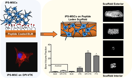
Non-native peptides derived from a combinatorial phage display are engineered to increase iPS-MSC attachment on biomaterials and increase the quantity and uniformity of bone and vasculature formation in vivo. Findings validate phage display as a new technology platform to engineer the interface between selective cell populations and specific biomaterial chemistries.
1. Introduction
Mesenchymal stem cells (MSCs) are a promising source for cell-based bone regeneration. [1,2] Since their initial discovery in the bone marrow stromal niche, MSCs have been identified in various adult and neonatal tissues, including but not limited to adipose tissue, peripheral blood, amniotic fluid, and umbilical cord.[3] MSCs can also be derived from embryonic and induced pluripotent stem cell (iPS) lineages.[4–6] Induced pluripotent stem cell derived MSCs are of clinical interest because they provide a more continuous and uniform supply of cells compared to primary MSCs and avoid concerns that exist with embryonic stem cells.
Bioresorbable natural and synthetic polymers, calcium phosphates and sulfates and polymer-mineral composite materials are frequently used as scaffolds to deliver cells to bone defects.[7,8] Tunable mechanical properties, controlled degradation rates, and scalable manufacturing afford synthetic polymers significant advantages over naturally derived polymers.[9–11] Incorporating a mineral component provides additional mechanical support and recapitulates a chemical microenvironment conducive to osteogenecity.[12,13] Amongst the various methods of incorporating a mineral component onto a biomaterial, growth of a mineral layer by immersion in simulated body fluid (SBF) containing the ionic concentrations of blood plasma under physiological pH is a promising strategy because it avoids high temperature and pressure processing.[13–15] The bone-like mineral (BLM) layer resulting from SBF immersion has been characterized in detail and is compositionally and microstructurally similar to bone, thereby improving osteoconductivity in vitro and bone formation in vivo.[11,12,16] Nanoscale morphology, crystallinity, and compositional characteristics of the mineral surface increase adsorption of cell-adhesive serum proteins like fibronectin and vitronectin which subsequently increase osteoconduction.[17–19] However, the chemical and physical properties of the mineral alone are insufficient to selectively adhere cells.
Due to the limitations of covalently tethering instructive molecules to mineral substrates, mineral binding ECM proteins and peptide domains have been used for presentation of cell adhesive peptides to imorganic biomaterials.[20,21] For example, the glutamic acid repeat motif (E7) in bone sialoprotein was combined with RGD to increase adsorption of RGD to BLM and promote osteoconductivity.[22] Although the RGD-E7 peptide improves osteoconductivity on mineralized biomaterials in vitro, it inhibits osseointegration in vivo.[17] The varied successes with RGD and other integrin binding peptides prompted the identification of cell specific peptides that can selectively bind bone forming cell populations from a heterogeneous stem or progenitor source.
To meet the objective of selectively binding MSCs to mineralized biomaterials, we used phage display coupled with bioinformatic approaches and in vitro screening techniques to identify MSC-specific [DPIYALSWSGMA, DPI] and apatite-specific [VTKHLNQISQSY, VTK] sequences which were combined into a dual peptide [GGDPIYALSWSGMAGGGSVTKHLNQISQSY, DPI-VTK] for cell specific adhesion to mineralized biomaterials.[23,24] DPI-VTK efficiently targets apatite and increases adhesion strength and specificity to human and murine MSCs and induced pluripotent stem cell derived mesenchymal stem cells (iPS-MSCs).[25] Moreover, DPI-VTK improves spreading and proliferation while supporting differentiation on dual peptide coated constructs compared to non-peptide coated controls. These findings suggest a role for MSC driven bone formation in vivo by the DPI-VTK peptide.
In addition to increasing the quantity of tissue, increasing the uniformity of regenerated tissue throughout a defect site is an important design goal. In this study, we hypothesize that increasing iPS-MSC attachment and uniformity of distribution in 3D using phage-derived peptides will lead to increased quantity and uniformity of regenerated bone and vasculature in vivo. This hypothesis was tested by functionalizing mineralized PLGA scaffolds with the DPI-VTK peptide and comparing outcomes to BLM controls, RGD-VTK, and P15 coated BLM. The ubiquitous cell binding domain RGD was combined with the mineral binding domain VTK to be used as a dual-peptide positive control (RGD-VTK) for in vitro characterization (Table 1). P15 peptide, a component of Pep-Gen P15-BGS (Dentsply Implants, CA) currently available as a bone graft substitute for void filling and augmentation, was used as an in vivo positive control.[26–28]
Table 1.
Peptide Properties
| Peptide | Sequence | Description | MW (g/mol) | Net Charge | Acidic residues |
|---|---|---|---|---|---|
| VTK | VTKHLNQISQSY | Phage derived mineral binding sequence | 1417.59 | 1 | 2 |
| DPI-VTK | GGDPIYALSWSGMAGGGSVTKHLNQISQSY | Dual functioning peptide containing phage derived cell and mineral binding sequences | 3025.35 | 0 | 5 |
| RGD-VTK | GGRGDGGGSVTKHLNQISQSY | Dual functioning peptide containing cell binding control sequence and phage derived mineral binding sequence | 2061.20 | 1 | 3 |
| P15 | GTPGPQGIAGQRGVV [23] | Col1a1 derived cell and mineral binding peptide for in vivo control | 1393.57 | 1 | 0 |
2. Results
2.1. Mineral Distribution on BLM Scaffolds
Spatially continuous mineral coverage on porous PLGA scaffolds was achieved across all groups. Average mineral volume fractions (MV%) for all treatment groups were 16.5±3.8%. Filtration of SBF resulted in mineralization through the thickness of each scaffold (Figure 1, a–f). There were no significant differences in MV% between regions, except for a greater fraction of mineral in the interior region (shell 5) compared to the exterior region (shells 1 and 2) (Figure 1g, p < 0.001, n=10). Greater mineralization in the interior region may arise from increased turbulent flow conditions, and early nucleation within the interior of the scaffold pores. Regardless, there was no observable pore occlusion that limits transport and vascularization.
Figure 1:

Morphology and distribution of bone-like mineral precipitated into the pores of PLGA scaffolds. Representative MicroCT image of mineralized scaffold rendered in MicroView®(A). Representative images of mineral distribution in volumetric shells progressing from the outermost to innermost regions of the scaffold (B-F). Fraction of mineral volume from the outermost to the innermost volumetric shell of the scaffolds (G). * indicates significant difference from sections 1 and 2 (p<0.001, n = 10).
2.2. Delivery of Peptides to Mineral Scaffolds
Peptide adsorption on mineralized scaffolds was not different between VTK, DPI-VTK and RGD-VTK groups (Figure 2a, n=6). Peptide adsorption on 3D scaffolds was uniform for each peptide and uniform within each region across peptides, with the exception of more VTK than RGD-VTK in the outermost section (Figure 2c, p <0.02). The fraction of adsorbed peptide was not different within peptide groups (Figure 2c).
Figure 2.

Peptide adsorption and distribution on mineralized PLGA Scaffolds(n=6). (A) There was no significant difference between VTK, DPI-VTK and RGD-VTK (B) Schematic and representative images of DPI-VTK distribution depicting relative position of each cryosection (1–5 in Z direction) and sampled region (a-e radially) within corresponding sections. Each image is a composite stack of 40 images projected in the Z direction based on average intensity (scale bar 0.5mm). (C) Uniform distribution of adsorbed peptide (n=6) across all groups was analyzed using Image J (NIH) software with a customized concentric circle algorithm. * indicates significant difference from Section 1 of RGD-VTK (p <0.02).
2.3. Cell Seeding Efficiency on Peptide-Laden Scaffolds
There was more efficient iPS-MSC seeding on VTK (p<0.04), DPI-VTK (p<0.002), RGD-VTK (p<0.001), and serum coated BLM (p<0.001) compared to serum-free BLM control groups (Figure 3a). RGD-VTK exhibited higher seeding efficiency than BLM (p<0.001), VTK (p<0.001), and DPI-VTK (p<0.01). All peptide groups demonstrated uniform cell distribution across radial sections, except the percent of cells adherent to the outermost section on VTK coated scaffolds was greater than the middle and inner-most sections (Figure 3b; p<0.001). Moreover, there was a greater fraction of cells adherent to the innermost region of scaffolds coated with DPI-VTK peptide compared to BLM (p<0.001), VTK (0.01) and RGD-VTK (p<0.001).
Figure 3.

Cell Seeding efficiency and distribution on peptide coated scaffolds(n=6). A) Seeding efficiency on peptide coated scaffolds based on histomorphometric analysis. *** indicates significant difference from DPI-VTK (p<0.01), VTK (p<0.001), and BLM (p<0.001). ** indicates significant difference from VTK (p <0.05) and BLM (p <0.002) groups. * indicates significant difference from BLM (p<0.04) group. B) Fraction of adherent cells by spatial location indicating higher cell fraction bound to VTK in section 1 compared to BLM (*, p<0.02). ** indicates higher cell fraction bound to DPI-VTK in section 5 compared to BLM (p<0.001), VTK (p<0.1) and RGD-VTK (p<0.001).
2.4. MSC Differentiation on Peptide Coated BLM In Vitro
There was greater Runx2 expression on DPI-VTK compared to BLM controls (p < 0.023, Figure 4a), whereas expression on RGD-VTK and P15 exhibited no significant difference. OSX exhibited greater expression on DPI-VTK(p <0.05) and RGD-VTK (p < 0.001), on day 14 compared to day 3. There was greater OSX expression on RGD-VTK (p < 0.001) on day 14 (Figure 4b) compared to BLM. Similarly, across all peptide groups, ALP expression (Figure 4c) was greater on days 14 and 21 compared to day 10 (p < 0.001). ALP expression peaked earlier on DPI-VTK(day 14) compared to RGD-VTK(day 21). There was higher ALP expression on DPI-VTK on day 14 (p<0.01) compared to BLM controls. There was higher OCN expression on DPI-VTK at day 14 (Figure 4d) compared to BLM controls(p<0.001), RGD-VTK(p<0.001), and DPI-VTK on day 10 (p < 0.001).
Figure 4.

Differentiation of iPS-MSCs on bone like mineral and peptide coated bone like mineral characterized by gene expression levels of early(RUNX2, OCN) and late(ALP, OCN) osteogenic gene epression markers(n=3). A) Relative gene expression of osteogenic transcription factors Runx2 * significant difference from BLM day 14 (p < 0.023, n = 3), B) Relative gene expression of osteogenic transcription factors and Osterix(OSX) * from day 3(p<0.001, n=3), significant difference from BLM ^(p < 0.001, n = 3), #(p < 0.05, n = 3). C) Relative expression of genes regulating ALP - grey bars indicate significant difference of groups from day 10 p<0.001), * indicates significant difference from DPI-VTK and BLM on day 14(p<0.001, n=3) ŝignificant difference from BLM(p<0.01, n=3) D), Relative expression of genes regulating OCN * greater than BLM controls, RGD-VTK and day 10(p < 0.001, n=3)
2.5. Competitive MSC Binding Assays
Competitive binding assays were conducted to identify potential iPS-MSC surface receptors involved in binding cells to DPI-VTK. Soluble RGD or integrin antibodies compete with peptides bound to biomaterial surfaces for cell surface integrins. Soluble RGD and specific integrin antibodies were added in suspension to reach equilibrium with MSC integrin receptors and seeded on DPI-VTK or RGD-VTK coated materials to verify competition with the same integrin binding receptors. Cell attachment was significantly greater in the absence of soluble RGD compared to all concentrations for both DPI-VTK and RGD-VTK (Figure 5a, p<0.001). Cell attachment was significantly greater in the presence of 0.01mM soluble RGD compared to 0.1 or 1mM RGD (p < 0.02). There was greater cell spreading in the absence of soluble RGD on both DPI-VTK and RGD-VTK (Figure 5b). There were significantly less adherent cells in the presence of RGD binding integrin subunits compared to no integrin blocking controls and blocking the collagen binding integrin α2β1 (p < 0.001) on both DPI-VTK and RGD-VTK coated BLM films (Figure 5c). The adherent cell fraction on DPI-VTK in the presence of αV, α5, and β3 was significantly greater compared to RGD-VTK, indicating a weaker interaction between these domains and DPI peptide compared to RGD.
Figure 5.

iPS-MSC competition with soluble integrin binding competitors(n=6). A) Fraction of adherent cells on peptide coated BLM in the presence of soluble RGD normalized to no soluble competitors. * denotes significant difference from other concentrations of soluble RGD within peptide group (p<0.01). ** denotes significant difference from the 0.1 and 1mM concentrations (p<0.02) within each peptide group. B) Representative images at 40x of MSCs on DPI-VTK and RGD-VTK coated substrates in the presence and absence of soluble RGD. Nuclei are stained with DAPI and F-actin is stained with rhodhamine-pholloidin (scale bars 5 µm). C) Fraction of adherent cells on peptide coated BLM in the presence of RGD integrin binding receptors and a Col1 binding receptor normalized to absence of soluble competitors. * denotes difference from RGD binding integrins (p <0.001). Bars denote difference from RGD-VTK within same soluble treatment group (p <0.05).
2.6. Bone Volume Fraction and Distribution In-Vivo
MicroCT images reveal, qualitatively, greater bone formation on scaffolds with DPI-VTK and P15 compared to acellular scaffolds without peptide, acellular scaffolds with peptide, cellular scffolds without peptide and cellular scaffolds with just the mineral binding peptide (Figure 6a). Scaffolds coated with both DPI-VTK and P15 exhibited shell formation characteristic of ectopically reconstructed ossicles. Quantitatively, there was a significantly greater BVF in constructs coated with DPI-VTK compared to VTK (p < 0.002), BLM (p <0.037), acellular DPI-VTK (p <0.003) and acellular BLM controls (Figure 6b, p < 0.003). P15 coated constructs had a significantly greater BVF than BLM (p <0.05) and acellular BLM (p <0.005). There were noticeable differences between VTK coated constructs and uncoated and acellular controls but statistically insignificant due to large variance.
Figure 6.

Bone volume fractions of ectopically regenerated bone 8 weeks post iPS-MSC transplantation (n=6). Representative rendered MicroView® images of bone regenerated with A) acellular bone-like mineral (BLM), acellular BLM containing DPI-VTK, BLM with iPS-MSCs, BLM containing VTK with iPS-MSCs, BLM containing DPI-VTK with iPS-MSCs, P15 coated BLM constructs with iPS-MSCs (scale bar=1mm). B) Bone volume fractions from MicroCT analysis indicate significantly greater bone formation in scaffolds with DPI-VTK and P15 compared to VTK, BLM, DPI-VTK acellular and BLM acellular controls. * indicates a significant difference from BLM and acellular BLM (p <0.001). ** indicates a significant difference from VTK (p < 0.001), BLM (p < 0.001), acellular DPI-VTK (p < 0.001) and acellular BLM controls (p < 0.001).
Rendered MicroCT images of concentric shells of regenerated bone (Figure 7a–e) revealed greater bone formation towards the peripheral sections compared to interior sections. DPI-VTK coated constructs had a significantly greater fraction of bone in section 1 compared to section 5 (p<0.002) and section 4 (p<0.003), as well as a greater fraction of bone in section 2 compared to section 5 (p<0.005) and section 4 (p<0.008) (Figure 7f). Similarly, P15 coated constructs had a greater fraction of bone in section 1 compared to section 5 (p<0.004) and section 4 (p<0.005), as well as a greater fraction of bone in section 2 compared to section 5 (p<0.015) and section 4 (p<0.019). VTK coated constructs had a greater fraction of bone in section 2 compared to sections 4 (p<0.004) and 5 (p <0.026).
Figure 7.

Distribution of regenerated bone 8 weeks post iPS-MSC transplantation (n=6). A-E) Representative images of concentric volumetric shells of bone engineered on bone-like mineral coated with phage-derived peptide DPI-VTK progressing from the outermost to innermost region of regenerated bone. F) Fraction of total bone by peptide revealing significantly greater fraction of bone towards the periphery compared to the interior regions in peptide groups. * indicates significant difference from sections 4 and 5.
2.7. Histology of Regenerated Bone
There was greater bone formation on DPI-VTK and P15 coated constructs compared to VTK and BLM constructs (Figure 8 a–h). Cells seeded on BLM with VTK led to some bone formation surrounding scaffold pores (p), however the DPI-VTK and P15-laden constructs exhibited more robust bone formation and were relatively devoid of pores (p) and struts (t). Ossicles regenerated from BLM and VTK coated scaffolds look compressed and elongated compared to pre-transplanted scaffolds, whereas bone regenerated from DPI-VTK and P15-coated constructs was larger than the originally transplanted constructs, which is consistent with the quantitative BV data. Regenerated bone from DPI-VTK and P15 also demonstrated greater vascularization (h) and cellularity (c) compared to VTK coated and BLM constructs. Bone scores also indicate greater bone formation on DPI-VTK and P-15 compared to VTK and BLM (Figure 8i; p <0.001). Vascular scores indicate a greater hematopoetic population and vascular structures on DPI-VTK and P15 compared to BLM and VTK constructs (Figure 8j; p<0.001) There were no differences in bone score within different sections of scaffolds for each peptide group, but across sections (Figure 8k), DPI-VTK and P15 exhibited greater bone scores compared to VTK and BLM (p <0.001). Similarly, DPI-VTK and P15 exhibited higher vascular scores compared to VTK and BLM (Figure 8l; p<0.001), but no differences in scores were observed within sections.
Figure 8.

Histological staining and bone quality scoring of regenerated bone 8 weeks post transplantation(n=5). A-D) Representative low magnification images of cross sections through the center of ossicles, indicating overall degree of bone formation in the interior of the constructs (scale bar 500µm). E-H) High Magnification images of cross sections through the center of ossicles indicating increased bone formation, vascularization, and cellularity on DPI-VTK and P15 compared to VTK and BLM. (b) indicates bone, (h) indicates hematopoesis, (c) indicates greater density of cells, (p) indicates pores, (t) indicate scaffold struts replaced by tissue (scale bars 100µm). I) Bone score based on bone coverage. * indicates significant differences from BLM and VTK (p <0.001). J) Vascular score by peptide group. * indicates significant differences from BLM and VTK (p <0.001). K) Bone score by section across peptide groups. * indicates significant difference from BLM and VTK (p<0.001). L) Vascular score by section across peptide groups. * indicates significant difference from BLM and VTK (p<0.001).
3. Discussion
Phage-display, a techonology commonly used in the design of pharmecutical biologics, is relatively new to the field of regenerative medicine. This powerful bacteriophage tool, combined with computational bioinformatics, provides a novel technology platform to design cell instructive biomaterials through surface engineering. We have demonstrated the significance of utilizing phage-display to develop a non-obvious, modular peptide design strategy and show equivalence in bone formation to current clinical bone augmentation therapeutics, P15, which is nased on already known ECM protein sequences.
iPS-MSCs transplanted onto DPI-VTK coated mineralized biomaterials increased bone formation in-vivo compared to non-peptide coated, VTK-coated and acellular controls (Figure 6,7). Moreover, bone formed by cells transplanted on DPI-VTK coated constructs exhibited increased cellularity and vascularization compared to uncoated, VTK and acellular controls (Figure 8). Although seeding efficiency was greater on DPI-VTK and serum-coated BLM compared to VTK (Figure 3a, p < 0.05), the DPI peptide promotes cell specific attachment of MSC populations compared to RGD-VTK.[24] There was also a greater percentage of iPS-MSCs within the innermost region of DPI-VTK coated constructs compared to RGD-VTK, VTK, and BLM (Figure 3), indicating greater migration into the interior of the scaffold. Peptides containing the mineral specific sequence, VTK (VTK, DPI-VTK, RGD-VTK) demonstrated affinity to BLM coated scaffolds(Figure 2a).
Micro-CT cannot distinguish bone from Ca/P biomaterials. Thus, for mineralized biomaterials, the initial mineral volume is commonly subtracted from the final bone volume to calculate regenerated bone volume. However, these calculations assume that the mineralized substrates do not resorb over the course of the transplantation in-vivo. Coating porous scaffolds with BLM nucleated from 2x SBF results in a rapidly dissolving Ca/P shell that is almost completely resorbed, as evidenced by the negligible fraction (2–3% BVF) in the acellular controls (Figure 6a) compared with the starting mineral volume fraction of 16.5% (Figure 1). Cells transplanted onto BLM formed from 2x SBF, resulted in poor bone formation compared to previous studies utilizing mineral precipitated from 1x SBF. Moreover, a thrombin-fibrin clot is typically used to provide further retention of cells within a Ca-P construct. Using a fibrin clot would have prohibited the direct testing of the peptide, and inability to use a fibrin clot could have resulted in poor bone formation in BLM-coated materials compared to previous studies. Although there were no differences in total volume, bone volume fraction or bone scores of regenerated bone between P15 and DPI-VTK coated cellular constructs, further engineering the dual peptide by modifying the spacer, arrangement of the sequence or incorporating post translational modifications to increase cell specificity could lead to greater bone formation than the clinically derived P15 peptide.
Cell-seeded constructs, especially those containing MSCs, can drive vascularization through secretion of pro-angiogenic factors contributing to hematopoesis which concomitantly drives greater bone formation[1,29]. Hematopoetic regions were evident across all cell-transplanted treatment groups and greater cell numbers were observed within constructs coated with DPI-VTK and the positive control P-15 (Figure 8). A shell of bone at the exterior of the scaffold, resulting in a spatial gradient in bone formation, was evident in both P15 and DPI-VTK coated constructs (Figure 6). A shell is commonly formed in an ectopic model.[30–32] The subcutaneous environment is physically and temporally limited by the ability to form deeply penetrating vascular networks before cell mediated mineralization causes pore occlusion and isolation of the interior regions.[33] Both bone and vascular regions were present throughout constructs containing DPI-VTK and P15 (Figure 8). In DPI-VTK coated materials, vascularization was equivalent in all regions and not compromised in the interior. Bony spicules within the center regions of both DPI-VTK coated and P15 coated constructs exhibited thick cellularized sections which is inconsistent with latent mineral from pre-implanted sources. Despite the shell formation, DPI-VTK promoted moderate bone formation penetrating 60% of the scaffold interior.
Early expression of Runx2 and OSX followed by increased ALP expression compared to controls indicate more osteogenic differentiation of MSCs on DPI-VTK and RGD-VTK compared to BLM (Figure 4). The promotion of earlier osteogenic differentiation of MSCs by DPI-VTK in vitro suggests a cell instructive role. For instance, growth and differentiation of transplanted MSCs results in greater cell secreted factors that can drive bone regeneration. The increased expression of early and late stage osteogenic differentiation markers in vitro and improved bone formation in-vivo on DPI-VTK coated mineral scaffolds suggest peptide mediated mechanotransductive pathways could be driving greater bone formation in vivo. MSCs adhere with more uniform fibrillar cell substrate contacts on bone-like mineral surfaces compared to more peripheral focal adhesion contacts on non-coated surfaces[19]. Peptides strongly adsorbed to the substrate may further increase the formation of these strong fibrillar contacts thereby driving mechanotransductive pathways. Various osteogenic pathways are activated through focal or fibrillar contacts at the cell-substrate interface leading to kinase activation and osteogenic signal transduction at these adhesion sites[34,35]. The phage display derived cell binding sequence, DPI, could be selective towards a profile of integrins or cell adhesion molecules driving strong cell substrate interactions which may be driving greater bone formation.
Competition with soluble RGD indicated the role of RGD binding integrins in mediating MSC-DPI interactions (Figure 5a). Furthermore, inhibition of cell spreading on DPI-VTK in the presence of soluble RGD (Figure 5b) demonstrated the requirement of RGD binding integrins in mediating cell spreading on DPI-VTK. Competition with RGD-binding integrin antibodies α5, β1, αV, β3, β5 further confirmed the role of RGD-binding integrins in mediating DPI-VTK cell attachment (Figure 5c). The differences in adherent cell fractions between DPI-VTK and RGD-VTK in the presence of integrin antibodies can be attributed to either different affinities or conformational flexibility in binding different integrin domains. The promiscuity of DPI-VTK adhesion to a panel of RGD binding integrins may be attributed to phage display selection of cell surface targets that are highly expressed. MSCs express a distinct profile of integrins at distinct differentiation times.[36–38] Therefore, these phage derived peptides may be adhering to one or more integrin targets in addition to other cell adhesive molecules thereby driving greater MSC specific adhesion strength as previously observed and contributing towards the increase in bone formation.
The improvement in in vivo osteogenic potential provided by DPI-VTK warrants further investigation towards the mechanism of action. Future studies to elucidate specific cell binding targets in addition to conformational regulation of DPI when present with the material-binding VTK sequence can further improve the osteogenic potential of these phage derived peptides. As tissue engineering shifts from developing technologies to meet general clinical challenges to addressing more focused clinical applications, there will be an increased need for delivering cell specific cues to material surfaces with defined surface chemistries. [23,39] Combinatorial phage display is a powerful technology platform to enable focused cell based tissue regeneration through the discovery of cell specific and material specific peptide sequences.
4. Conclusion
Combinatorial phage display identified a bioactive peptide sequence that increases osteogenesis and vascularization on mineralized 3D biomaterials in vivo. In addition to improving cell attachment to mineral surfaces, this dual peptide improved ostogenic differentiation and attachment to integrin binding domains implicated in osteogenic differentiation pathways. Constructs containing DPI-VTK formed more bone, contained more cells, and exhibited greater and more uniform vascularization compared to acellular controls, non-peptide coated BLM and VTK coated BLM. Modular design of non-native peptides using combinatorial phage-display catalyzed bone and vasculature formation equivalent to the clinical control, collagen-based P15 peptide, and further mechanistic inquiries can guide and refine the peptide driven cell instruction towards increased quality and quantity of regenerated bone and vasculature.
5. Experimental Section
Mineralized Scaffold and Film Fabrication:
Polylactic-co-glycolic acid (PLGA 85:15, Lakeshore Biomaterials) was solubilized in chloroform at 5%w/v. NaCl was sieved to 250–425µm and packed into 5mm diameter wells in a Delrin® mold. PLGA-chloroform solution was added to each well of the Delrin® mold which was then covered and dried for 36hrs. The mold was transferred to a vacuum chamber for 5 days and NaCl was leached in double-distilled water (ddH2O) for 36hrs with intermittent fluid changes. Porous scaffolds were etched in 0.5M sodium hydroxide under slight agitation and rinsed twice in ddH2O. Scaffolds were mineralized by filtration of simulated body fluid (SBF) through interconnected pores as described.[40] SBF (1x) contains 141 mM NaCl, 4.0 mM KCl, 0.5 mM MgSO4, 1.0 mM MgCl2, 4.2 mM NaHCO3, 5.0 mM CaCl2•2H2O,and 2.0 mM KH2PO4.[41] 2x SBF and 4x SBF solutions titrated to pH 6.4 with 1M NaOH were sterile filtered using a 0.22µm filter and 0.005% sodium azide was added to prevent bacterial contamination. A Delrin® mold containing scaffolds was attached to the actuator of an Instron 8521 servo-hydraulic system. The mold was lowered into a base containing a volume of pre-warmed 4x SBF (37oC) to fully submerge all scaffolds during the course of mineralization. The mold was cycled at an amplitude of 25.4mm at 0.011Hz. The 4x SBF was changed every 6 hours the first day and replaced with 2x SBF which was changed every 12 hours on days 2–5. Solution temperature in the base was maintained at 37oC using a heating sleeve connected to a thermocouple and temperature controller (Extech Instruments). Mineralized scaffolds (5mm diameter x 2 mm thickness) were carefully detached from the mold, rinsed in ddH2O for 12 hrs, air-dried in a biosafety cabinet for 12 hrs and stored in a desiccator.
Bone-like mineral films were used to characterize cell differentiation in vitro and competitive inhibition of cell binding to peptide coated surfaces. Mineral films were prepared by immersing PLGA thin films in simulated body fluid to precipitate carbonated apatite with plate like nanofeatures. A 5% w/v 85:15 polylactic-co-glycolic acid (PLGA, Lakeshore Biomaterials)-chloroform solution was cast on 15mm diameter glass slides. The PLGA films were etched in 0.5M NaOH and immersed in modified simulated body fluid (mSBF) for 5 days at 37°C with fluid changes every 24 hrs. The mSBF was made by dissolving the following reagents in Millipore water at 25°C and titrating to pH 6.8 using NaOH: 141 mM NaCl, 4.0 mM KCl, 0.5 mM MgSO4, 1.0 mM MgCl2, 4.2 mM NaHCO3, 5.0 mM CaCl2•2H2O, and 2.0 mM KH2PO4.
Peptide Synthesis:
Peptides (Table 1) were synthesized at the University of Michigan peptide core. All peptides were chemically synthesized using solid phase synthesis and protective chemistry. HPLC was used to verify > 95% purity. Peptides were stored at −20oC until further use.
Peptide Loading on Mineralized Scaffolds:
Scaffolds pre-wet overnight in ddH2O were sterilized, transferred to a new micro-plate, and incubated in Trizma buffer for 4hrs at 37oC. Peptides were weighed, dissolved in sterile ddH2O, and diluted in Trizma buffer pH 7.4. Scaffolds were immersed in peptide solution (100µg/mL) and gently agitated for 3hrs at 37oC. Pierce BCA assay (Thermo-Fisher Scientific Inc.) was used to determine total peptide amount on scaffolds (n=6) and compared to a standard curve (1–200 µg mL−1). Peptide distribution on scaffolds was assessed using fluorescein isothiocyanote (FITC) tagged peptides (n=6).
Cell Culture and Seeding on Peptide Coated Scaffolds:
Mesenchymal stem cells derived from induced pluripotent stem cells (iPS-MSCs) were a generous gift from Dr. Paul Krebsbach and Dr. Luis Villa. These cells were verified for osteogenic differentiation and bone forming potential in vivo.[5] iPS-MSCs were cultured in (α-MEM), 10% FBS, antibiotics, 200mM L-glutamine, and 10mM non-essential amino acids. iPS-MSCs (passage 5) were expanded twice when they reached 80–90% confluence before transplantation. Growth media was replaced every 2–3 days and switched to osteogenic media and supplemented with osteogenic factors (10−8M Dexamethasone, 2–5mM β-glycerophosphate, 10−4 M ascorbic acid) for 7 days prior to transplantation. Peptide-coated scaffolds were placed into 100uL PCR tubes. Confluent iPS-MSCs (passage 7) were trypsinized and suspended in either serum-free or complete media in a 20µL volume containing 50,000 cells. The cell suspension was seeded into each scaffold for 3hrs at 5% CO2 and 37oC.
Peptide and Cell Distribution on Mineralized Scaffolds:
Fluorescently tagged peptide coated scaffolds were paper-embedded in cryosection molds in freezing media (OCT, Tissue Tek) on a bed of dry ice and acetone.[42] Cell-seeded scaffolds (n=6/group) were fixed in 10% phosphate buffered formalin and paper embedded in cryosection molds in freezing media (OCT, Tissue Tek) on a bed of dry ice and acetone.[42] A Leica cryostat was used to make five 200µm thick sections through the thickness of each scaffold. Sections were mounted in Vectashield (Vector Laboratories) and imaged using a Nikon Ti-Eclipse confocal microscope. Sections were imaged at constant intensity and gain settings across all samples using a 4x objective that incorporated the entire section in the field of view.[43] Edges were clipped to limit artifact and 40 images were acquired for each section at 5µm intervals. Image J software (NIH) was used to stack 40 images projected in the Z direction. A modified concentric circle algorithm was used to measure fluorescence intensity in the corresponding circle within each section - outermost circle for section 1 to innermost circle for section 5 (Figure 2b).
MSC Differentiation:
Mineralized films were held in place with Teflon O-rings for differentiation assays to prevent films from floating. Films were incubated in peptide solution(100 μg mL−1) for 3 hrs. iPS-MSCs were plated (15,000 cells cm−2) and grown to confluence until differentiated in complete media containing osteogenic factors (10−8M Dexamethasone, 2–5mM β-glycerophosphate, 10−4 M ascorbic acid). Cells were differentiated for 0, 3, 7, 10, 14, 21, 28 days and collected (n=3) in TRIZOL® (ThermoFisher Scientific). Cells were homogenized in TRIZOL®, phase-separated in chloroform, and RNA was precipitated in 500μL isopropanol, washed in 80% ethanol, dried and dissolved in RNA grade double distilled water (Milipore) at 70oC. The amount of RNA was measured using a spectrophotometer and 1μg was used for reverse transcription using SuperScript II reagents (ThermoFisher Scientific). TaqMan® Universal PCR Master Mix and Taqman primer probes RUNX2 (Hs01047973_m1), OSX(Hs01866874_s1), ALP(Hs03674916_s1), OCN(Hs01587814_g1) were used for qRT-PCR reactions. Cycle threshold (CT) values for each gene of interest(GOI) were normalized to GAPDH expression to attain ΔCT and day zero values were used as a baseline to attain ΔΔCT.[44] Fold changes (2- ΔΔCT) are depicted in Figure 4, delta-delta CT (ΔΔCT) values were used for statistical analysis.
Competitive Attachment of MSCs to Peptides:
iPS-MSCs were incubated in the presence of competing antibodies αV, α5, β1, β3, β5, α2β1 (Cell Signaling Technology, 10μg mL−1) or soluble RGD (1, 0.1, 0.01mM) for 10 min at 37oC under slight agitation (n=6). [45–47] Mineralized films were attached to the bottom of 24 well plates with sticky tabs. Cells suspended in serum-free media with soluble RGD or integrin antibodies were subsequently added to peptide-coated mineral films (100µg mL−1) for 3 hours in the presence of inhibitors. Adherent cells were measured using a WST-1 assay and a standard curve from 100–10,000 cells. Cells were subsequently fixed, F-actin was stained with Rhodhamine-Pholloidin, and nuclei were stained with DAPI. Fluorescent images were acquired using a Nikon Ti-Eclipse confocal microscope.
Transplantation of Cell-Seeded Constructs:
Peptide coated scaffolds and uncoated mineralized control scaffolds were placed in PCR tubes and statically seeded in a 20µL volume of complete media containing 3 × 10⁶ cells on each construct for 3 hours. This micromass seeding method was used to improve seeding efficiency. Cell seeded scaffolds (n=6) were stored on ice prior to transplantation. Acellular mineralized scaffolds and acellular mineralized scaffolds coated with DPI-VTK were included as controls (n=4). All surgical procedures were performed in accordance with NIH guidelines for the care and use of laboratory animals (NIH Publication #85–23 Rev. 1985) and the University of Michigan’s Committee on Use and Care of Animals. Female nude mice (NIH-Lystbg-JFoxn1nuBtkxid, Charles Rivers) between 25–30g were anesthetized with isoflurane in O2 (5% induction and 2% maintenance at 1mL min−1). A midline longitudinal incision was made on the back of each mouse and 4 pockets (2 on each side) were made in the subcutaneous tissue beneath the dorsal skin. Scaffolds were randomly placed into each pocket and the incision was closed with surgical staples. Animals were sacrificed 8 weeks postoperatively and transplants were harvested.
Microcomputed Tomography:
Mineralized scaffolds (prior to cell seeding and transplantation) and ossicles of regenerated bone were assessed using Scanco μCT 100 at 10 μm voxel size at 10 μm slice increments. Bones were fixed in 4% phosphate buffered formalin prior to imaging. MicroCT scans were obtained at 70kV, 114 A using a 0.5 Al filter. Reconstructed images of all scaffolds and bones were analyzed using the Scanco μCT evaluation tool to calculate mineral volume fractions (MVF, n=10) and bone volume fraction(BVF, n=6) respectively. Reconstructed images were rendered in (MicroView, Parallax Innovations Inc) using the isosurface tool at a threshold of 1000 with the smoothing filter and a surface quality factor of 0.51. A custom volumetric shrinkage algorithm was used to generate five concentric volumetric shells each 20% smaller than the previous volume. Total volumes and volume fractions were calculated for each shell and compared across the five volumetric shells to examine mineral and bone distribution from the exterior toward the interior of the scaffold. Mineralized scaffolds were distributed by MVF across control and treatment groups so that there were no initial statistical differences in mean MVF amongst groups. Bone volume fractions are presented unadjusted by initial mineral volume fractions because a majority of initially implanted mineral was resorbed 8 weeks post-implantation in acellular controls.
Histology and Histomorphometry:
Ossicles were decalcified in 10% EDTA. Transplants (n=5) were sectioned through the midline, paraffin embedded, and 5µm thick triplicate sections were made of 3 ossicle regions progressing from the interior to the periphery. Sections were subsequently deparaffinized, hydrated, and stained with hematoxylin and eosin. A 20x field of view was used to scan sections and assess bone coverage. Totals for each ossicle region were averaged. Sections were scored for bone and vasculature using parameters outlined in Table 2.[48,49]
Table 2.
Histological Scoring Parameters
| Score | Bone Coverage | Score | Vascularization |
|---|---|---|---|
| 0 | No Bone | 0 | No blood vessels |
| 1 | 1%−5% in a particular region | 1 | Some vessels in a particular region |
| 2 | 5%−10% in a particular region | 2 | Some vessels throughout construct |
| 3 | 10%−25% throughout section | 3 | Moderate vessels in a particular region |
| 4 | >25% throughout section | 4 | Moderate-Many vessels throughout construct |
Statistical Analysis:
All data are presented as mean ± standard deviation (SD). Statistical analysis was conducted using Sigmaplot 13.0 (Systat Software Inc. Chicago, IL). One-way ANOVA on ranks using a Tukey test for pairwise comparison was used to compare initial mineral fraction (n=10), peptide adsorption (n=6), cell seeding (n=6), bone score (n=5) and vascular score (n=5) across treatment groups. One-Way ANOVA on ranks with Dunn test for pairwise comparisons was used to assess bone volume fractions(n=6). Two-Way ANOVA on ranks using Tukey test for pairwise comparisons was used to assess peptide (n=6), cell (n=6), mineral (n=10) and bone volume distribution (n=6) as a function of peptide and location. Tukey post-hoc pairwise comparisons were also used to analyze competitive inhibition (n=6) and cell differentiation (n=3). Data was considered significant if p < 0,05.
Acknowledgements
We would like to thank Dr. Paul Krebsbach and Dr. Luis Villa for the induced pluripotent stem cells. Funded by NIHDE015411 R01DE026116.
6. References
- [1].Caplan AI, Tissue Eng 2005, 11, 1198. [DOI] [PubMed] [Google Scholar]
- [2].Bianco P, Robey PG, Development 2015, 142, 1023. [DOI] [PMC free article] [PubMed] [Google Scholar]
- [3].Hass R, Kasper C, Böhm S, Jacobs R, Cell Commun. Signal 2011, 9, 12. [DOI] [PMC free article] [PubMed] [Google Scholar]
- [4].Brown SE, Tong W, Krebsbach PH, Cells. Tissues. Organs 2009, 189, 256. [DOI] [PMC free article] [PubMed] [Google Scholar]
- [5].Villa-Diaz LG, Brown SE, Liu Y, Ross AM, Lahann J, Parent JM, Krebsbach PH, Stem Cells 2012, 30, 1174. [DOI] [PMC free article] [PubMed] [Google Scholar]
- [6].Russo V, Yu C, Belliveau P, Hamilton A, Flynn LE, Stem Cells Transl. Med 2014, 3, 206. [DOI] [PMC free article] [PubMed] [Google Scholar]
- [7].Kretlow JD, Mikos AG, J. Biomed. Mater. Res. A 2011, 98, 323. [DOI] [PMC free article] [PubMed] [Google Scholar]
- [8].Lee EJ, Kasper FK, Mikos AG, Ann. Biomed. Eng 2014, 42, 323. [DOI] [PMC free article] [PubMed] [Google Scholar]
- [9].Lu L, Peter SJ, Lyman MD, Lai HL, Leite SM, Tamada JA, Vacanti JP, Langer R, Mikos AG, Biomaterials 2000, 21, 1595. [DOI] [PubMed] [Google Scholar]
- [10].Wu L, Ding J, Biomaterials 2004, 25, 5821. [DOI] [PubMed] [Google Scholar]
- [11].Murphy WL, Hsiong S, Richardson TP, Simmons C. a, Mooney DJ, Biomaterials 2005, 26, 303. [DOI] [PubMed] [Google Scholar]
- [12].Kretlow JD, Mikos AG, Tissue Eng 2007, 13, 927. [DOI] [PubMed] [Google Scholar]
- [13].Murphy WL, Kohn DH, Mooney DJ, J. Biomed. Mater. Res 2000, 50, 50. [DOI] [PubMed] [Google Scholar]
- [14].Luong LN, Hong SI, Patel RJ, Outslay ME, Kohn DH, Biomaterials 2006, 27, 1175. [DOI] [PubMed] [Google Scholar]
- [15].Segvich SJ, Kohn DH, Biological Interactions on Materials Surfaces, Springer US, New York, NY, 2009. [Google Scholar]
- [16].Murphy WL, Simmons C. a., Kaigler D, Mooney DJ, J. Dent. Res 2004, 83, 204. [DOI] [PubMed] [Google Scholar]
- [17].Hennessy KM, Clem WC, Phipps MC, Sawyer AA, Shaikh FM, Bellis SL, Biomaterials 2008, 29, 3075. [DOI] [PMC free article] [PubMed] [Google Scholar]
- [18].Ramaswamy DH, Ramaraju JS, and Kohn, in Biol. Biomed. Coatings Handbook, Process. Charact (Ed: Zhang S), CRC Press, Boca Raton, FL, 2011, pp. 1–36. [Google Scholar]
- [19].V Leonova E, Pennington KE, Krebsbach PH, Kohn DH, J. Biomed. Mater. Res. A 2006, 79, 263. [DOI] [PubMed] [Google Scholar]
- [20].Gilbert M, Shaw WJ, Long JR, Nelson K, Drobny GP, Giachelli CM, Stayton PS, J. Biol. Chem 2000, 275, 16213. [DOI] [PubMed] [Google Scholar]
- [21].Masica DL, Gray JJ, Biophys. J 2009, 96, 3082. [DOI] [PMC free article] [PubMed] [Google Scholar]
- [22].Fujisawa R, Mizuno M, Nodasaka Y, Kuboki Y, Matrix Biol 1997, 16, 21. [DOI] [PubMed] [Google Scholar]
- [23].Segvich SJ, Smith HC, Kohn DH, Biomaterials 2009, 30, 1287. [DOI] [PMC free article] [PubMed] [Google Scholar]
- [24].Ramaraju H, Miller SJ, Kohn DH, Biomaterials 2017, 134, 1. [DOI] [PMC free article] [PubMed] [Google Scholar]
- [25].Ramaraju H, Miller SJ, Kohn DH, Connect. Tissue Res 2014, 55 Suppl 1, 160. [DOI] [PMC free article] [PubMed] [Google Scholar]
- [26].Gomar F, Orozco R, Villar JL, Arrizabalaga F, Int. Orthop 2007, 31, 93. [DOI] [PMC free article] [PubMed] [Google Scholar]
- [27].Artzi Z, Kozlovsky A, Nemcovsky CE, Moses O, Tal H, Rohrer MD, Prasad HS, Weinreb M, Int. J. Oral Maxillofac. Implants 2008, 23, 1063. [PubMed] [Google Scholar]
- [28].Emam H, Beheiri G, Elsalanty M, Sharawy M, Int. J. Oral Maxillofac. Implants 2011, 26, 561. [PubMed] [Google Scholar]
- [29].Robey PG, Kuznetsov SA, Riminucci M, Bianco P, Methods Mol. Med 2007, 140, 83. [DOI] [PubMed] [Google Scholar]
- [30].Rossello RA, Kohn DH, J. Biomed. Mater. Res. B, Appl. Biomater 2009, 88, 509. [DOI] [PMC free article] [PubMed] [Google Scholar]
- [31].Byers BA, Guldberg RE, García AJ, Tissue Eng 10, 1757. [DOI] [PubMed] [Google Scholar]
- [32].Wendt D, Marsano A, Jakob M, Heberer M, Martin I, Biotechnol. Bioeng 2003, 84, 205. [DOI] [PubMed] [Google Scholar]
- [33].Stephansson SN, Byers BA, García AJ, Biomaterials 2002, 23, 2527. [DOI] [PubMed] [Google Scholar]
- [34].Chen CS, Tan J, Tien J, Annu. Rev. Biomed. Eng 2004, 6, 275. [DOI] [PubMed] [Google Scholar]
- [35].Comisar WA, Mooney DJ, Linderman JJ, J. Theor. Biol 2011, 274, 120. [DOI] [PMC free article] [PubMed] [Google Scholar]
- [36].Kundu AK, Khatiwala CB, Putnam AJ, Tissue Eng. Part A 2009, 15, 273. [DOI] [PMC free article] [PubMed] [Google Scholar]
- [37].Popov C, Radic T, Haasters F, Prall WC, Aszodi a, Gullberg D, Schieker M, Docheva D, Cell Death Dis 2011, 2, e186. [DOI] [PMC free article] [PubMed] [Google Scholar]
- [38].Docheva D, Popov C, Mutschler W, Schieker M, J. Cell. Mol. Med 11, 21. [DOI] [PMC free article] [PubMed] [Google Scholar]
- [39].Atala A, Kasper FK, Mikos AG, Sci. Transl. Med 2012, 4, 160rv12. [DOI] [PubMed] [Google Scholar]
- [40].Segvich S, Smith HC, Luong LN, Kohn DH, J. Biomed. Mater. Res. B, Appl. Biomater 2008, 84, 340. [DOI] [PMC free article] [PubMed] [Google Scholar]
- [41].Kokubo T, Kushitani H, Ohtsuki C, Sakka S, Yamamuro T, J. Mater. Sci. Mater. Med 1992, 3, 79. [Google Scholar]
- [42].Peters SR, A Practical Guide to Frozen Section Technique, Springer Science & Business Media, New York, 2010. [Google Scholar]
- [43].Vivek M, Srividhya PK, Sujatha K, Int. J. Appl. Eng. Res 2016, 11, 2518. [Google Scholar]
- [44].Schmittgen TD, Livak KJ, Nat. Protoc 2008, 3, 1101. [DOI] [PubMed] [Google Scholar]
- [45].Rowley J. a., Madlambayan G, Mooney DJ, Biomaterials 1999, 20, 45. [DOI] [PubMed] [Google Scholar]
- [46].Petrie T. a., Capadona JR, Reyes CD, García AJ, Biomaterials 2006, 27, 5459. [DOI] [PubMed] [Google Scholar]
- [47].Feng Y, Mrksich M, Biochemistry 2004, 43, 15811. [DOI] [PubMed] [Google Scholar]
- [48].Boyan BD, Lohmann CH, Somers a., Niederauer GG, Wozney JM, Dean DD, Carnes DL, Schwartz Z, J. Biomed. Mater. Res 1999, 46, 51. [DOI] [PubMed] [Google Scholar]
- [49].Mankani MH, Kuznetsov SA, Wolfe RM, Marshall GW, Robey PG, Stem Cells 2006, 24, 2140. [DOI] [PubMed] [Google Scholar]