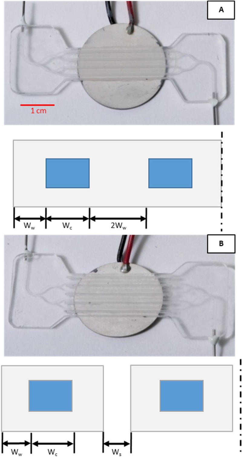
FIG. 3.
Photographs of four-channel test device mounted to transducer and cross-section diagrams below to show relative dimensions (not to scale). (a) No-slot design with width of the wall, width of the fluid cavity, and dashed line indicating symmetry plane. (b) Slotted design with gap of width between neighboring channels. All other dimensions are the same as in (a).

