



Abstract
Background:
Systems neuroscience experiments often require the integration of precisely timed data acquisition and behavioral monitoring. While specialized commercial systems have been designed to meet various needs of data acquisition and device control, they often fail to offer flexibility to interface with new instruments and variable behavioral experimental designs.
New method:
We developed a Teensy 3.2 microcontroller-based interface that is easily programmable, and offers high-speed, precisely timed behavioral data acquisition and digital and analog outputs for controlling sCMOS cameras and other devices.
Results:
We demonstrate the flexibility and the temporal precision of the Teensy interface in two experimental settings. In one example, we used the Teensy interface to record an animal’s directional movement on a spherical treadmill, while delivering repeated digital pulses that can be used to control image acquisition from a sCMOS camera. In another example, we used the Teensy interface to deliver an auditory stimulus and a gentle eye puff at precise times in a trace conditioning eye blink behavioral paradigm, while delivering repeated digital pulses to trigger camera image acquisition.
Comparison with existing methods:
This interface allows high-speed and temporally precise digital data acquisition and device control during diverse behavioral experiments.
Conclusion:
The Teensy interface, consisting of a Teensy 3.2 and custom software functions, provides a temporally precise, low-cost, and flexible platform to integrate sCMOS camera control into behavioral experiments.
Keywords: Teensy, Arduino, microcontroller, sCMOS camera, open-source, spherical treadmill, ADNS-9800 gaming sensor
1. Introduction
Recent advances in sCMOS camera technology and genetically encoded calcium indicators enable fluorescence imaging of neuronal activity patterns during behavior (Mohammed et al., 2016; Nguyen et al., 2016; Gritton et al., 2019). Using a standard wide-field microscope system, sCMOS cameras can offer routine imaging of large brain areas of millimeters in diameter at a micrometer spatial resolution, and tens of frames per second acquisition rate, allowing simultaneous measurement of thousands of individual neurons. One key technical aspect of neural activity analysis during behavior is temporal precision, where neural activities need to be precisely aligned with behavioral features. However, it has been difficult to integrate sCMOS cameras, deployed in large scale calcium imaging studies, with devices needed to monitor and control behavioral experiments. Traditional Analog/Digital interfaces are often operated by programs, such as MATLAB, that offer a wide range of applications. However, MATLAB or other PC-based high-level programming languages can lead to undesired temporal delays, as the PC operating system needs to balance the demands of many system operations at once. To achieve the temporal precision needed, optimized MATLAB functions or LabVIEW programs may be deployed, which can present a steep learning curve for people without sophisticated programming skills. Thus, a user-friendly interface that can integrate a sCMOS camera into behavioral experiments with high temporal precision is desired, especially for researchers with limited programing skills.
Over the last decade, microcontrollers traditionally marketed to hobbyists have gained popularity across a variety of scientific fields (D'Ausilio, 2012; Sanders and Kepecs, 2014; Grinias et al., 2016; Husain et al., 2016; Chen and Li, 2017; Saphet et al., 2017). For example, Arduino microcontrollers have recently been integrated into two-photon imaging experiments (Wilms and Hausser, 2015; Takahashi et al., 2016; Micallef et al., 2017). Microcontrollers are small, low-cost, and capable of delivering digital outputs with microsecond time precision. Arduino, which utilizes user-friendly, open-source software functions, was the first major microcontroller to gain substantial popularity. Recently, Teensy 3.2 microcontrollers were developed, which have all the key features of the current version of the standard Arduino microcontroller (Arduino Uno Rev3), as well as the additional feature of delivering analog output. Teensy microcontrollers utilize the same open-source Arduino software environment, and thus remain easy to program (D'Ausilio, 2012). Because of the simplicity of microcontrollers and their temporal precisions, microcontrollers represent an attractive solution to precisely record data and monitor experimental progress.
Here, we demonstrate and characterize a flexible Teensy 3.2-based interface for temporally precise data acquisition and delivery of analog and digital signals, during a voluntary movement tracking experiment and a trace conditioning eye blink learning experiment. The Teensy interface can deliver digital pulses with microsecond precision to initiate individual image frame capture using the camera’s external trigger settings at a desired frequency, while simultaneously collecting animal behavioral data. We also demonstrate the ability of the Teensy interface to generate analog sound waveforms to drive speakers for a trace conditioning eye blink experiment. Together, these results demonstrate that the Teensy interface, consisting of a Teensy microcontroller and a set of custom software functions, offers a flexible, accurate, and user-friendly environment for imaging experiments during behavior.
2. Methods
2.1. Construction of Teensy 3.2 boards
Experimental hardware designs are shown in Figure 1. The specialty components required to build these designs are shown in Tables 1 and 2. In both experiments, a Teensy 3.2 (PJRC.COM, LLC, part #: TEENSY32) (Figure 1A), or a Teensy 3.2 soldered to a prop shield (PJRC.COM, part #: PROP_SHIELD) (Figure 1B), is mounted on top of a standard printed circuit board (PCB) (for example: Digi-Key, part #: V2010-ND) via standard female headers (such as SparkFun Electronics, PRT-00115). Female headers were then soldered to the PCB for stability. Output from the Teensy was directed from pins on the female headers to standard SMA connectors (such as: Digi-Key, part # CON-SMA-EDGE-S-ND) via 22 gauge wires (for example: Digi-Key, part #1528-1743-ND). Coaxial cables were then attached to the SMA connectors on the PCB to connect the Teensy to external devices. The Teensy was connected to a computer via a standard USB-microUSB cable (for example: Digi-Key, part # AE11229-ND). To easily upload code to the Teensy, we used PlatformIO (https://platformio.org/), an add-on to the widely-used Atom text editor (https://atom.io/), instead of the default Arduino programming environment. Code for each of the two experimental settings were uploaded separately to the Teensy prior to each experiment. To turn digital pins on and off, and also to change their modes to either “input” or “output”, we used a slightly modified version of the DigitalIO library provided by PlatformIO (version 1.0.0; currently maintained at: https://github.com/greiman/DigitalIO). Once the Teensy is connected to a PC via a USB cable, it automatically initializes (i.e. runs a “setup” function). To easily set experiment-specific parameters for the Teensy, such as sampling frequencies, trial numbers and trial length, and the length of an experiment, we developed simple MATLAB graphical user interfaces (GUI), one for each experiment that allows experimenters to fine-tune task parameters for their experiments. Using the GUI, a recording session is initiated by pressing “Start.”
Figure 1.
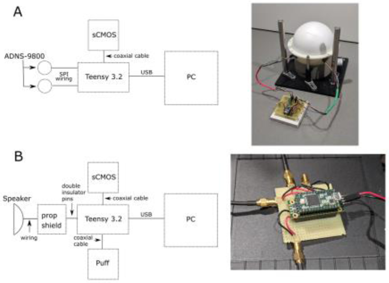
Diagrams of the two experimental device arrangements using a Teensy interface. A. Motion tracking experiment design. This design consists of a Teensy 3.2 connected to two ADNS-9800 sensors via serial-peripheral interfaces, and a sCMOS camera through a coaxial cable. Every 50 milliseconds, a digital pulse was sent to initiate an image frame capture from a sCMOS camera. Simultaneously, the Teensy interface acquired motion data from both ADNS sensors and sent them to a PC via a USB. B. Trace conditioning eye blink experiment design. This design consists of consists of a Teensy 3.2 connected to a speaker through a prop-shield that contains an amplifier. Every 50 milliseconds, a digital pulse was sent to initiate an image frame capture from a sCMOS camera. Simultaneously, the Teensy interface generated digital pulses to generate air puff and updated the status of the analog output to generate audio signals, and sent the timing of these signals to a PC via a USB.
Table 1.
Specialty components necessary to build a motor output system
| Part name | Website | Part number | Cost per unit |
|---|---|---|---|
| Teensy 3.2 | https://www.pjrc.com/store/teensy32.html | TEENSY32 | $19.80 |
| ADNS-9800 sensors | https://www.tindie.com/products/jkicklighter/adns-9800-laser-motion-sensor/ | ADNS-9800 Laser Motion Sensor | $27.50 |
Table 2.
Specialty components necessary to build a tone-puff system.
| Part name | Website | Part number | Cost per unit |
|---|---|---|---|
| Teensy 3.2 | https://www.pjrc.com/store/teensy32.html | TEENSY32 | $19.80 |
| 14x1 Double insulator pins | https://www.pjrc.com/store/header_14x1_d.html | HEADER_14x1_D | $0.85 |
| Prop shield | https://www.pjrc.com/store/prop_shield.html | PROP_SHIELD | $19.50 |
2.2. Animal procedures
All animal procedures were approved by the Boston University Institutional Animal Care and Use Committee. Two 8-12 week old female C57BL/6 mice were used in this study (Taconic; Hudson, NY). Detailed surgical procedures are as described previously (Mohammed et al., 2016; Gritton et al., 2019). Briefly, mice were first stereotaxically injected with 250nL of AAV9-Syn-GCaMP6f.WPRE.SV40 virus (acquired from the University of Pennsylvania Vector Core, titer ~6e12 GC/ml), into the CA1 region (AP: −2 mm, ML: 1.4 mm, DV: −1.6 mm). The injection was made at 40 μl/min, using a 10 nL syringe (World Precision Instruments, Sarasota, FL) with a 33 gauge needle (NF33BL; World Precision Instruments, Sarasota, FL). The injection rate was commanded by a microsyringe pump (UltraMicroPump3–4; World Precision Instruments, Sarasota, FL). After the mice recovered, they were fitted with a custom imaging window composed of a stainless steel cannula (OD: 0.317 cm., ID: 0.236 cm., height 2 mm) attached to a coverslip (size 0; OD: 3 mm), via UV-curable adhesive (Norland Products). Cortical tissue was aspirated to allow the imaging window to be placed directly on top of CA1. An aluminum head-plate was also affixed to the skull to allow head fixation. Mice were trained on an eye-blink task in an identical fashion to Mohammed et al. (2016), or habituated to run on a spherical treadmill as described in Gritton et al. (2019).
2.3. Motion tracking experiment
In this experiment, we performed motion tracking using two ADNS-9800 gaming sensors (Tindie, part: “NS-9800 Laser Motion Sensor”, see Table 1), while delivering digital pulses that can be used to trigger a sCMOS camera for image capture every 50 ms. The overall design of this experiment is shown in Figure 1A. A mouse was positioned on top of a buoyant Styrofoam ball floated by house air as described previously (Dombeck et al., 2007). Two ADNS-9800 gaming sensors were positioned at the equator of the Styrofoam ball, at an angle of approximately 75 degrees from one another. ADNS-9800 sensor boards can measure up to 8200 counts per inch, allowing for more sensitive measurement of mouse movement relative to other tracking devices while remaining low cost. For example, standard computer mice, such as the Logitech M100 (Logitech, PN: 910-001601), measure up to 1000 counts per inch. Thus the ADNS-9800 sensor, at its highest setting, is about 8 times as sensitive. In our experiments, we set the ADNS-9800 sensor at a value of 3400 counts per inch.
The total distance travelled by the mouse at any time point was computed using the following equation:
Where yR and yL. are the y readings from the left and right sensors, and θ is the angle between the two sensors (75 degrees). We also acquired readings in the “x” direction from both sensors, which can be used to calculate rotation. Velocity was computed as the distance divided by the time between two adjacent readings, as measured by the Teensy. These two sensors were connected to the Teensy via simple serial peripheral interface (SPI) connections with insulated 22 gauge wires as shown in Figure 2A.
Figure 2.
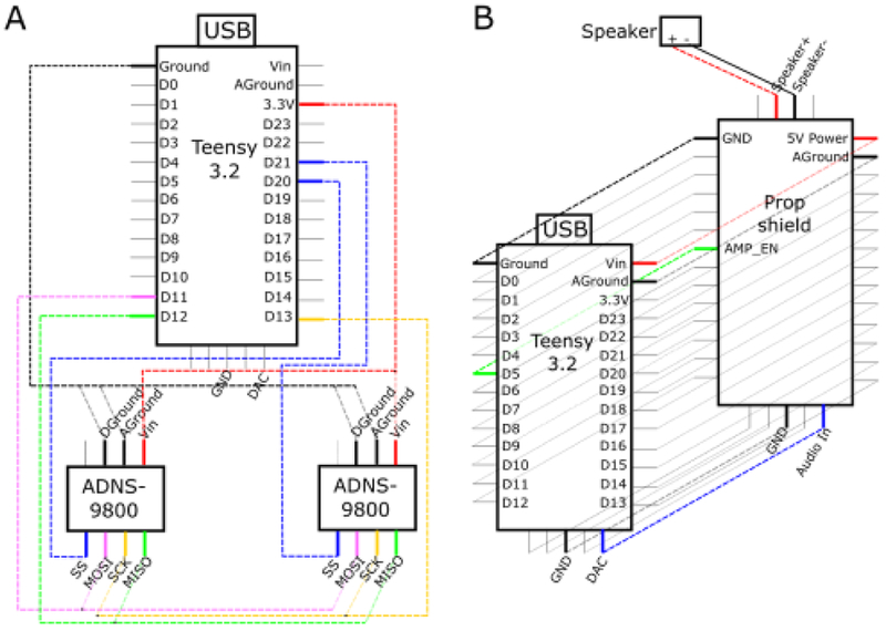
Electrical wiring schematics for the motion tracking experiment and the trace conditioning eye blink experiment A. The schematic of the wiring of a Teensy 3.2 to two ADNS-9800 sensors via serial peripheral interface connections (SPIs). Solid dots at intersections between dotted lines indicate electrical connections. Unused pins on the Teensy were not included in this schematic. The Teensy’s ground pin was connected to both AGround and DGround pins (analog and digital ground) on both ADNS-9800 sensors. The D11 pin (D = digital) was connected to both MOSI (“Master-Out, Slave-In”) pins, the D12 pin was connected to both MISO pins (“Master-In, Slave-Out”), the D13 pin was connected to both SCK pins (SPI Clock), and the 3.3V pin was connected to both Vin (voltage in) pins on the ADNS-9800 sensors. Finally, pins D20 and D21 were connected individually to each SS pin (Slave Select) on the ADNS-9800 sensors. The DAC pin (digital to analog converter or the analog output pin) is also shown. B The schematic of the wiring of a Teensy 3.2, a prop shield, and an external speaker. Dotted lines indicate connections. Connections between the Teensy and prop shield were made using 14x1 double insulated pins according to the manufacturer’s instruction (https://www.pjrc.com/store/prop_shield.html), and the prop shield audio output was connected to the speaker using 22 gauge wire. We highlight that that the Teensy DAC pin is connected to the “Audio In” pin on the prop shield, both of which are labeled. Additional pins utilized by the prop shield for amplification were also labeled.
To control experimental timing, we utilized the “IntervalTimer” function, unique to the standard Teensy library, which can repeatedly call a function at specified intervals. We set the “IntervalTimer” to be 50,000 microseconds (50 ms) or 20 Hz in our experiment. Using IntervalTimer, we repeatedly called a function that sent the accumulated displacements of the motion sensor readings to the attached PC. We acquired the x and y displacement readings from each sensor with freely available functions on GitHub (https://github.com/markbucklin/NavigationSensor), which read accumulated displacement from the “motion burst” register of each sensor. After reading the motion sensor, a digital “on” pulse that lasted for 1 ms was sent out of a digital pin designed to initiate an image frame capture from a sCMOS camera. To characterize the temporal precision of different digital pulses generated by the custom script using the “IntervalTimer” function, we recorded the digital outputs with a commercial system (Tucker Davis Technologies RZ5D (TDT RZ5D)) at 3051.76 Hz.
The GUI for this experiment allows a user to specify a filename, the length of each trial, the sampling rate, and the options to start or stop an experiment at any time. The “Stop” button sends data serially to the Teensy 3.2, which terminates the experiment and resets all experimental parameters set on the Teensy board. The GUI records, on the attached PC, the Teensy-reported time stamps of each frame, the Teensy-reported duration of each frame, and the displacement in the X- and Y- directions of the ADNS-9800 sensors during each time frame.
2.4. Trace conditioning eye blink experiment
In this experiment, a Teensy was programmed to deliver outputs capable of eliciting a sound and initiating a short duration digital pulse to an air solenoid that allows a brief pulse of air to the eye (eye puff), while delivering digital pulses that can be used to trigger a sCMOS camera for image capture at a defined interval (every 50 ms in this demonstration). The overall design of this experiment is shown in Figure 1B. To deliver an audible sound through the Teensy, we used a Teensy prop shield module (PJRC.COM, LLC., part #: PROP_SHIELD) to amplify analog output (shown in Figure 2B as pin A14). This add-on component can drive speakers with resistances up to 8 ohms. The prop shield was soldered to the bottom of the Teensy with 14x1 double insulator pins (PJRC.COM, LLC., part #: HEADER_14x1_D), and the output was connected to a speaker, as shown in Figure 2B. The Teensy was then mounted onto the female headers separated by the prop shield, as shown in Figure 1B. The camera and air valve for the eye puff were attached to the microcontroller through coaxial cables (Figures 1B and 2B), and the speaker was connected with 22 gauge wire to the prop shield.
2.4.1. Trace conditioning eye blink experiment with single tone
We used the Teensy Audio library function “AudioSynthWaveformSine” to generate tones. This function continuously outputs a sine wave with a sampling rate of 44.1 kHz from the analog pin. We first initialized the tone, in this case a 9500 Hz sine wave, at the beginning of each experiment, but set the amplitude to “0”, so that the tone was off. At the desired time, we switched the amplitude to 0.05 (out of a maximum of 1) to generate an audible tone. The value of 0.05 generated a tone of approximately 75 dB with our amplifier and speaker settings.
We used the “elapsedMicros” function to control the timing of the experiment. elapsedMicros offers precise timing like “IntervalTimer”. and additionally allows for simultaneous use of the Audio library. This experiment is trial-based, and each trial consisted of an 11.1 second long baseline period, a 700ms long tone, a 250ms long delay period, a 100ms long puff period, and a 7.85 second long post-puff period. Using an “elapsedMicros” timer, we repeatedly called a function that updated the status of each digital and analog output every 50 ms based on the trial structure of the task, and then turned on the digital output directed to the sCMOS camera for 1ms every 50ms.
To demonstrate the feasibility of using the Teensy-interface to perform either trace conditioning with either one tone or two tones, the GUI includes the features of specifying two tones of different frequencies. For example, one tone serves as a neutral stimulus (NS) not followed with an unconditioned eye puff stimulus, whereas another tone of a different frequency serves as the conditioned stimulus (CS) followed with the unconditioned eye puff stimulus. In such experiments, each trial consists of a prestimulus period, the delivery of a NS or CS (randomly selected), the delivery of an unconditioned stimulus (gentle puff), and an inter-trial interval with temporal jitter. The GUI allows the user to specify a filename, 1 or 2 tones, the length of each trial, the range of temporal jitter, the number of trials, the timings of the tone(s), and the timing of a gentle puff with respect to the CS, and to start and stop an experiment at any time. The user can further specify the amplitudes of each of the tone(s), their frequencies and the tone duration, as well as the duration of the gentle puff. The GUI records, in the attached PC, the Teensy-reported time stamp of each image frame relative to the session and relative to the beginning of the trial, the trial number, and indicator variables (1s or 0s) which correspond to whether the sound or puff is on or off, respectively.
To characterize the temporal precision of different digital pulses generated by the custom scripts, we recorded the digital outputs with a commercial system (Tucker Davis Technologies RZ5D (TDT RZ5D)) at 3051.76 Hz, and the analog sine wave output at 24414.0625 Hz without additional amplification. To determine the onset of the analog audio signal, the unamplified analog output from the Teensy was first high-pass filtered at 1 kHz using a 6th-order, zero-phase Butterworth digital filter (MATLAB command “filtfilt”). We then estimated the instantaneous amplitude of the 9500 Hz sine wave at each time point using the Hilbert transform of the filtered signal. The first time point where the amplitude rose above 0.005 was considered the onset of the analog signal, and the subsequent time point where it dropped below 0.005 was considered the offset. To adjust the onset of the analog signal to the beginning of digital pulses, we utilized the continuous voltage output from the digital pin for consistency. To acquire the digital pulse onset coinciding with the beginning of the experiment from the continuous signal, we thresholded this continuous voltage output at a value of 1 V and took the first time point where the continuous voltage exceeded 1 V to be the start of the experiment. We aligned the analog sound recording using this as a landmark. To compare latencies, we compared tone onset times in the aligned analog recording to digital pulse time stamps from the digital output.
2.4.2. Trace conditioning eye blink experiment with two tones
In the two tone trace conditioning experiments, we utilized a 2000 Hz tone and an 8000 Hz tone, 800ms in duration, with the output amplitude set to 0.1 for both tones. The signal corresponding to the “puff” output was not recorded or monitored for this demonstration, though it was set to last for 400 ms beginning 1200 ms following the termination of the tone. The inter-trial interval was set to 20 +/− 5 seconds (range of [15, 25)), which translates in the Teensy code to 300-499 frames per trial at 20 Hz. The temporal precision of these two different tones were characterized similarly to that described above for the 9500Hz tone. To compare the onset latency of these two tones, we used 6th-order bandpass Butterworth filters, using lower and upper frequency cutoffs of 1000 and 3000 for the 2000 Hz tone and 7000 and 9000 for the 8000 Hz tone. Tone onsets are then identified as the first time point where the amplitude of the Hilbert transform of the filtered signals exceeded 0.025.
2.5. GCaMP6 Imaging
GCaMP6 imaging was performed with the same custom microscope as that used in Mohammad et al. (2016). To demonstrate that digital pulses delivered by the Teensy Interface can initiate precisely timed frame capture from the sCMOS camera, we recorded from the hippocampus of a mouse during trace conditioning eye-blink experiment using a single tone. This recording session consisted of 40 trials, each lasting 20 seconds.
GCaMP6 videos were processed using a standard processing pipeline, similar to that used in Mohammad et al (2016). Briefly, videos were processed in 2000 frame chunks and were first filtered using a homomorphic filter and motion corrected using a cross-correlation method. Motion corrected videos were then background-subtracted using a slightly modified methodology following Gritton et al. (2019) . Following background subtraction and before conversion to the uint8 data type, a constant value was added, which consisted of the median of the first 2000 mean background signal values, in order to prevent values from decreasing below zero. Then, pixel values were converted to the uint16 data type instead of the uint8 data type. Neurons were identified using the semi-automated image segmentation algorithm, ACSAT (Shen et al., 2018). Fluorescence traces were then obtained by averaging the pixel intensity of all pixels within each neuron. The normalized fluorescence (ΔF/F) values for each neurons were computed by first subtracting the mean fluorescence of the each neuron over the entire recording period, and then dividing by the mean.
2.4. Statistics
Statistics were performed in MATLAB. Linear models were constructed using the “fitlm” function in MATLAB 2017b. Root mean squared error was computed by taking the square root of the mean of the squared residuals from a linear model.
2.5. Code availability
All code is located at GitHub (https://github.com/mfromano/micro-control), which will be made public upon publication.
3. Results
Microcontrollers such as Arduino microcontrollers have gained popularity in neuroscience research, and provide a user-friendly interface, open-source software environment, low cost, and a highly flexibility for integration with different devices (D'Ausilio, 2012; Chen and Li, 2017; Micallef et al., 2017). Recently, the Teensy 3.2 has been developed, which has an analog output, a major improvement over the popular Arduino Uno. Teensy devices also have a comprehensive Audio library, as well as the “IntervalTimer” and the “elapsedMicros” functions capable of generating precisely timed events repeatedly. Here, we present a Teensy-based interface to integrate frame-by-frame image capture with behavioral experimental control and data acquisition.
3.1. Motion tracking experiment
In this experiment (Figure 3A), we recorded a mouse running on a spherical treadmill for 10 minutes. Motion data was acquired at 20 Hz concomitantly with digital outputs that can be used to trigger individual image frame capture from a sCMOS camera. To measure locomotion from awake head fixed mice, we used the Teensy interface to record from two ADNS-9800 motion sensors (Figures 1A and 2A). We calculated the velocity of the mouse, which averaged 2.16 + 4.46 cm/s over the 10 minute period (mean + std, n=12000 time points) with a maximum velocity of 35.9 cm/s (Figure 3B), in general agreement with velocities reported for head-fixed mice running on a spherical treadmill (Dombeck et al., 2007; Gritton et al., 2019).
Figure 3.
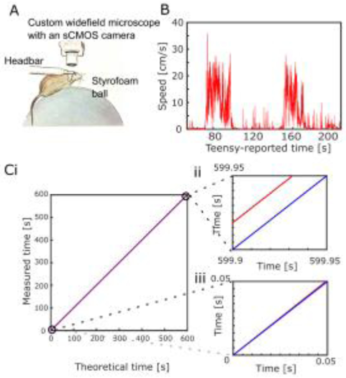
Temporal precision of the digital outputs in the motion tracking experiment. A. Illustration of the experimental setup, showing a mouse, awake and head-fixed, positioned on a Styrofoam ball. This can be positioned under an objective lens of a custom wide-field microscope equipped with a sCMOS camera. In this experiment, we did not perform calcium imaging with the sCMOS camera. (Illustration is modified from Gritton et al. (2019)). B. Example recording of a head-fixed mouse running on the spherical treadmill. C. Timing of digital pulses generated by the Teensy interface vs theoretical times of the digital pulses at exactly 20 Hz. Red line indicates linear model fit of experimental data, and blue line represents theoretic time with zero drift. The linear model of the experimental data estimates a slope of 1.000028937 + 0.000000002 (t(11998)= 4.9e+08, p < 0.001, R2=1; intercept = 0.0007593 + 0.0000007, t(11998) = 1.1e+03, p < 0.001). C(ii) and (iii) are zoomed in views of the beginning and end of the session.
To characterize the temporal precision of the Teensy interface, we measured the timing of the Teensy digital output, and compared it to the theoretical 20 Hz signal using a linear model. We found that digital outputs have a near-perfect linear relationship with the theoretical signal (Figure 3C). However, we noted a 28.9 μs per second positive drift, resulting in an actual frequency of 19.999 Hz instead of 20.000 Hz (Figure 3Cii and 3Ciii). To further examine whether this small timing drift depends upon the frequency of data acquisition or the timing of the digital outputs, we performed 5 minute long recording sessions without a live mouse at 20, 50, and 100 Hz, and a 0.5ms long digital pulse designed to trigger image capture from the camera. We found that the actual frequencies were 19.999, 49.999, and 99.997 Hz, respectively. These all correspond to an approximately 30 μs delay per second, suggesting that the timing drift is independent of the data acquisition rate and may reflect the processor timing of the Teensy microcontroller. However, because motion sensor data are monitored with respect to the Teensy’s timing, the animal’s locomotion data readings remain precisely aligned to the time when image frame capture occurs.
Having assessed the timing of the digital output, we next quantified its temporal variation. We calculated the root mean squared error (RMSE) of the difference between the recorded timing of each digital pulse and the times predicted from the linear model. The RMSE was 42.7 μs, computed manually. Together, these results demonstrate that the Teensy interface timed by the “IntervalTimer” function can be used to generate digital pulses for precise image frame capture during behavioral experiments, while maintaining alignment of imaging data with behavioral parameters.
3.2. Trace conditioning eye blink behavioral experiment
In a second experiment, we reconfigured the Teensy interface for a trace conditioning eye blink learning experiment (Figure 1B and 2B), where a mouse can be trained to associate a conditioned stimulus (700ms long tone) with a subsequent unconditioned stimulus (a 100ms long gentle eye puff), separated by a brief memory trace time window (250ms). We first characterized the temporal precision of the Teensy interface in a manner similar to that described in the motion tracking experiment. We recorded the timings of the digital pulses generated to trigger each image frame capture (Figure 4A), and detected a 33.4 microsecond delay per second. Thus, in this experiment, the Teensy interface has an actual frequency of 19.999 Hz instead of 20.000 Hz, identical to that observed in the motion tracking experiment. The RMSE of the Teensy interface is 13.3 μs computed manually, also similar to that observed in the motion tracking experiment.
Figure 4.
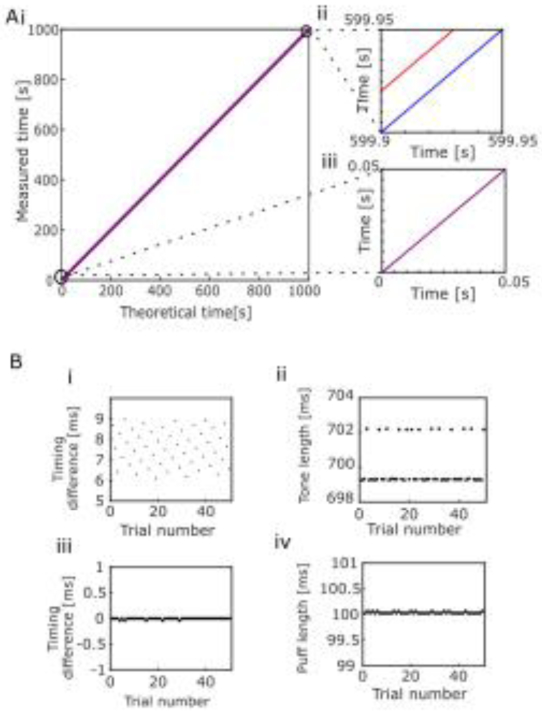
Temporal precision of the digital and analog outputs in the trace conditioning eye blink experiment. A. Timing of the digital pulses generated by the Teensy interface vs theoretical times of the digital pulses at exactly 20 Hz. Linear model fit for experimental data is shown in red, and in blue is a line representing a perfect, zero drift recording. (Linear model fit for experimental data: R2=1, slope: 1.0000334 + 0 (to machine precision), t(19998)=infinite, p<0.001). (ii) and (iii) are zoomed in views of the beginning and the end of the session. B. Timing of the analog output directed to the prop shield to generate an amplified auditory stimulus (i-ii) and the digital output directed to device to generate eye puff (iii-iv), both measured over 50 trials. (i) the difference between the onset of the analog output and the onset of the corresponding camera-directed digital pulse (mean=7.6 + 0.9 ms, range=2.9 ms); (ii) the duration of the auditory stimulus across all trials (mean=700 + 1 ms, range=2.9 ms, n=50 trials); (iii) the difference between the puff digital pulse and the camera-directed digital pulse, (mean= −0.004 + 0.012 ms, range=0.04 ms); (iv) the duration of the puff digital pulse (100.03+0.02 ms, mean + std, n=50 trials).
We then characterized the precision of multiple digital outputs by calculating the time difference between the digital pulses generated to drive the eye puff versus the sCMOS camera (Figure 4Biii). We found that there was nearly no temporal difference between the onset of these two digital outputs (−0.004 + 0.012 ms,mean + std, n=50 digital pulses). Similarly, the duration of the puff digital pulse was within 0.03 ms of the commanded duration of 100ms (Figure 4Biv) (100.03+0.02 ms (mean + std, n=50 digital pulses).
We next characterized the temporal precision of the analog output generated by the Teensy in the context of a trace conditioning experiment with a single tone. We measured the analog output of the Teensy with the commercial TDT RZ5D recording device sampled at 24414.0625 Hz. Since analog outputs were generated together with the onset of the digital outputs designed to trigger camera image frame capture, we calculated the time difference between the onset of the analog output and the onset of the digital pulse (Figure 4Bi, for details see Methods). We found that the analog output lagged the digital output by 7.6 + 0.9 milliseconds (mean + std, n=50 pulses, Figure 4Bi). This delay is comparable to that reported using a different configuration of the Teensy to play a sound (Solari et al., 2018). The duration of the tone remained equal to 700 + 1 ms, (mean +/− std, n=50 digital/analog pulses Figure 4Bii), equivalent to the commanded duration of 700ms. Together, these results demonstrate that the Teensy interface, timed by the “elapsedMicros” function, is capable of generating digital and analog output with microsecond temporal precision.
To further examine whether this delay was related to our implementation of the Audio library or from writing to the analog pin itself, we directly generated an analog pulse without the Audio library from the analog pin using the Arduino command “analogWrite(A14, 4050)”. “A14” corresponds to the analog pin, and 4050 is a relative voltage level large enough to be recorded as a pulse by the TDT RZ5D system. We initiated 50 trials consisting of 50 millisecond long pulses through a digital pin and through the analog pin. Pulses to these two pins were programmed to occur near-simultaneously. We found that the analog output lagged the digital output by 0.8 + 5.8 μs (mean + std, n=50 trials), suggesting that writing to the analog pin cannot account for the auditory signal delay generated through the Audio library. Thus the delay is due to the specific implementation of the Audio library, and future changes to the Audio library could improve the temporal precision.
3.4. Calcium imaging during trace eye blink conditioning using sCMOS camera controlled by the Teensy-interface
As a demonstration of the Teensy-interface in recording actual calcium data with a sCMOS camera, we performed calcium imaging in a mouse hippocampus during a single tone trace conditioning eye-blink experiment. The mouse was injected with the AAV-syn-GCaMP6f virus to express the genetically encoded calcium sensor GCaMP6f in the hippocampal CA1 region, and fitted with an imaging chamber that allows optical access to GCaMP6 expressing neurons. In this experiment, a mouse was first trained to associate a conditioned stimulus (CS) with a subsequent unconditioned stimulus (US) (a gentle eye puff), separated by a brief memory trace time window. The mouse was trained for seven days prior to this imaging session for 60 trials / day. All trials were separated by 30±5 seconds during the training phase while animals learned the CS-US association. On the imaging day shown here, the mouse was given 40 trials, each with an inter-trial interval of 20 seconds (Figure 5A). In both the training and imaging phases of the experiment, the mouse was head fixed under the imaging scope on a raised platform as described in Mohammed et al. (Mohammed et al., 2016). During this experiment, pulses were sent to the sCMOS camera, to capture calcium activity in the hippocampus at 20Hz from the Teensy. From the recording we identified 731 neurons (Figure 5B) across the imaging field. A large fraction of CA1 neurons recorded showed increased responsivity following the tone and prior to the puff (Figure 5C and 5D), suggesting a learned relationship for the CS-US as observed previously by Mohammed et al. (2016). Thus, the Teensy-interface in this demonstration allowed for easy implementation of the experimental paradigm and maintained precise timing throughout the recording period.
Figure 5.
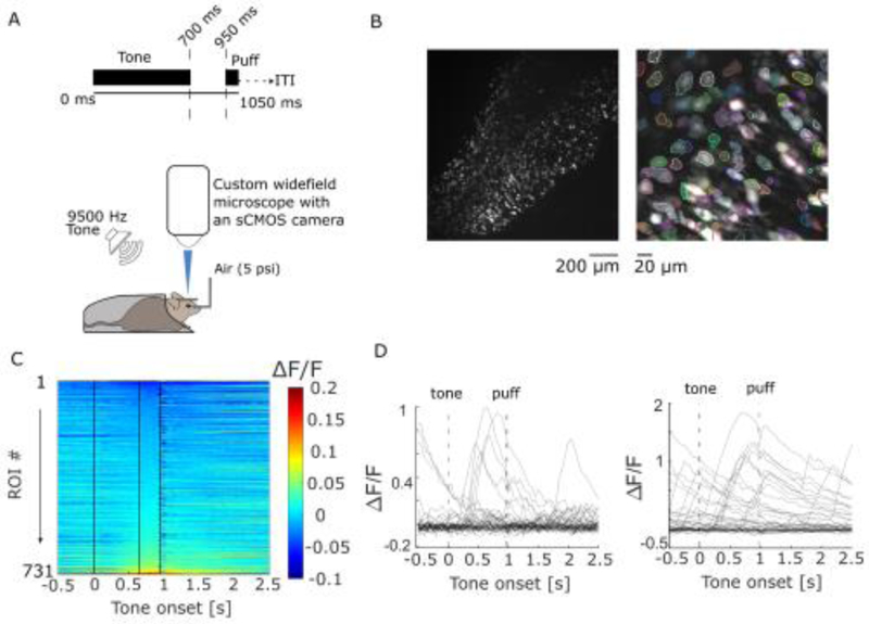
Calcium imaging with a sCMOS camera using the Teensy Interface during a trace conditioning eye blink experiment. A. The experimental timeline and experimental setup (adapted from Mohammed et al. (2016)). GCaMP6 fluorescence images were acquired using a sCMOS camera. The CS was a 75 dB tone delivered by a speaker, and the US was a gentle puff of air. Each trial consists of a tone and a puff, followed again by a temporally jittered inter-trial interval (ITI). B. A representative GCaMP6 fluorescence image across the imaging field (left), and a zoomed in view with identified ROIs overlaid (right). Shown is the max-minus-mean image of the first 5 minutes of the recording. C. Normalized ΔF/F values of GCaMP6 fluorescence intensity for all ROIs, aligned at tone onset. The three black lines indicate tone start, tone termination, and puff start, respectively. ROIs are sorted by their mean, trial-averaged ΔF/F values between the end of the tone and the start of the puff. D. Two example neurons and their ΔF/F values across all 40 trials. Dotted lines indicate tone and puff onsets.
3.5. Calcium imaging during trace eye blink conditioning using two tones
To showcase additional flexibility of the Teensy-interface, we adapted the single-tone trace eye blink conditioning experiment to a platform that can generate two tones allowing researchers to add an additional US to the experiment. In this variation, one tone could serve as a CS and the second a neutral stimulus (NS) that is not paired with an aversive eye puff outcome. We generated these two tones at different frequencies over 10 trials each (Figure 6), one at 8 kHz and the other at 2 kHz. The amplitude of both tones are set using the Audio library at a value of 0.1. We measured the tones generated by the Teensy-interface, and detected a latency of 7.1 + 0.9 ms (+/− std) for the 2 kHz tone, 6.8 + 0.9 ms for the 8 kHz tone. The latency for these two tones showed no difference (Wilcoxon rank-sum test, p=0.571, ranksum = 113), and were similar to that observed in the single tone trace conditioning eye blink experiment. Together, this example demonstrates the flexibility of the Teensy interface to command experiments with multiple audio stimuli.
Figure 6.
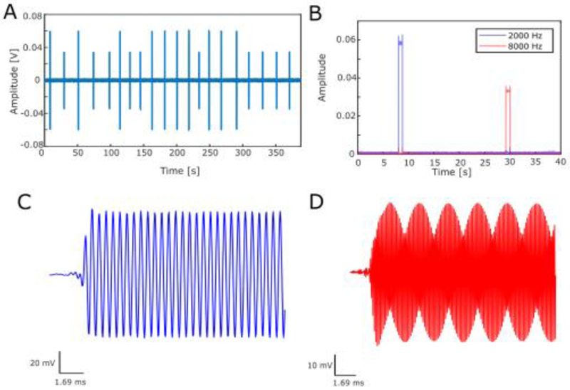
Demonstration of Teensy Interface in a two-tone trace conditioning eye blink experiment. A. An exemplar recording of the Teensy analog output that can be sent to a speaker to produce 2 tones. Shown are 388 seconds of recording, consisting of 20 trials, with each trial being 20 seconds in duration with up to 5 seconds of jitter. Signals were high-pass filtered at 1000 Hz for display purposes (high-pass, 6th order zero-phase Butterworth filter). B. Absolute value of the Hilbert transform of band-passed Teensy analog output signals as used in A. C, D. Example waveforms of the 2 kHz signals (C) and the 8 kHz signals (D) over the course of 0.0169 seconds. Signals shown were band-pass filtered at 2 kHz or 8 kHz.
4. Conclusion and Discussion
In both the motion tracking and the tone-puff trace conditioning experiments, the Teensy interface generated precisely timed digital pulses that can be used to control individual frame capture from a sCMOS camera at 20Hz. We detected a small drift, using the TDT RZ5D system, of approximately 30 μs per second, suggesting an actual frequency of 19.999 Hz instead of the commanded 20Hz. This small 0.003% drift of the Teensy processing clock is linear, and can thus be calibrated if desired. This finding underscores the importance of having a highly precise central timer in each experiment.
Synchronizing different devices such as sCMOS cameras only at the start of an experiment can lead to undesired temporal drifts, particularly in long experiments. Using a central timer instead of parallel, asynchronous controllers, however, is currently challenging. While MATLAB programs can be used to control experimental timing when integrating a sCMOS camera into a behavioral paradigm, they may introduce timing problems due to the concurrent demands of many PC system operations. For example, MATLAB offers a Data Acquisition Toolbox. However, learning how to optimize experiments using this toolbox is challenging, and can generate timing jitter due to suboptimal implementations. Such timing jitter may have a significant impact depending on the study, especially when millisecond time scale resolution is desired in systems neuroscience experiments. This is one of the major challenges with incorporating timing control and in particular with incorporating sCMOS cameras where precision capture is important in experimental design. Using a lower-level interface such as LabVIEW or using advanced MATLAB programming to control timing potentially obviate timing jitter, but both have steep learning curves, are proprietary, and have high costs. In contrast, with the Arduino programming environment it is simple to program basic experiments and because it is open source, there are many libraries on sites such as GitHub already available for adoption and use in experiments. Teensy boards are also inexpensive, and accompanying software and programming environments are free to download. Further, the GUIs that we have designed allow users of diverse scientific backgrounds to design a basic tone-puff experiment or motion control experiment without having to implement any Arduino programming at all.
Temporal accuracy is often important for animal behavioral training. For example, a precisely timed conditioned stimulus (tone) and unconditioned stimulus (puff) are important for animals to build association in trace conditioning eye blink experiments. We demonstrate that the Teensy interface can accurately generate multiple digital pulses to drive different devices, including the tone, the puff and the sCMOS camera. Additionally, we demonstrate that the Teensy interface precisely delivered longer duration digital and analog pulses, such as the tone that lasted for 700ms in the single tone trace conditioning eye blink experiment. These results demonstrate that the Teensy interface is a viable, inexpensive alternative that is also able to simultaneously capture imaging data using our simple software functions.
A major advantage of the Teensy over Arduino Uno microcontrollers is its ability to generate a true, 12 bit analog signal. While Arduino Uno microcontrollers can generate an analog-like signal via pulse-width modulation, this output is a square wave. We used the Teensy interface to deliver an auditory stimulus through the built-in Audio library, and our analog output showed a 7.6 ms delay during delivery of the single tone. This small delay is due in large part to the implementation of the Audio library. It is possible that other ways of utilizing the analog output would allow the generation of more temporally precise audio signals. However, altering the amplitude of a single sine wave via the Audio library is easy to implement, utilizing only a few lines of code within a single script.
4.1. Conclusion
We demonstrate a Teensy 3.2 interface capable of integrating a sCMOS camera into two behavioral experimental settings. In one setting, the Teensy interface simultaneously generates digital pulses that can be directed for individual frame capture from a sCMOS camera, while simultaneously tracking an animal’s locomotion using recently developed high precision ADNS-9800 gaming sensors. The easy integration of the sCMOS camera and the ADNS-9800 sensors illustrates the flexibility of the Teensy interface in designing experiments that require novel instrumentation. In the second experimental setting, we demonstrate that the Teensy interface, in conjunction with a prop shield, is capable of generating both analog and digital outputs with precise timing during an eye blink trace conditioning experiment. We characterized two timer functions, “IntervalTimer” and “elapsedMicros”. both of which offered equivalent microsecond temporal precision, and “elapsedMicros” additionally allows access to the Audio library. Thus the Teensy interface, a Teensy 3.2 and custom software functions, provides a user-friendly, easily adaptable, and temporally precise platform for integrating sCMOS cameras into behavioral experimental designs. This Teensy interface can be immediately adopted for the motion tracking and the trace conditioning eye blink behavioral experiments demonstrated here, or can be customized for other types of behavioral experiments where sCMOS camera-based imaging is desired.
Highlights.
Developed a low-cost, open source, Teensy 3.2-based interface for systems neuroscience that can be used to integrate novel instruments into experiments
Exhibit the temporal precision of the Teensy 3.2 interface in two experimental conditions
Demonstrate the utility of the Teensy 3.2 interface in generating analog signals (sound waveforms) and digital pulses simultaneously
Acknowledgements
M.F.R. performed data analysis. M.F.R. and H.J.G. conducted the motion tracking experiment. M.F.R. and H.J.G. conducted the trace conditioning eye blink experiments. M.F.R., M.B., and D.R.M. wrote the software. M.F.R., M.B., D.R.M., and R.K. contributed to the Teensy interface conceptualization. M.F.R., H.J.G., and X.H. wrote the manuscript. X.H. supervised the study. The authors would also like to acknowledge Thomas Romano for helpful conversations, and users “Theremingenieur” and “PaulStoffregen” from the PJRC forums (https://forum.pjrc.com/) for responding to questions relating to the trace eye blink conditioning experiment.
Funding sources
X.H. acknowledges funding from the National Institutes of Health (NIH) (1DP2NS082126, R01NS109794-01), NSF (CBET-1848029), Defense Advanced Research Projects Agency (DARPA) Young Faculty Award, Boston University Biomedical Engineering Department, and Boston University Photonic Center. M.F.R.
Footnotes
Publisher's Disclaimer: This is a PDF file of an unedited manuscript that has been accepted for publication. As a service to our customers we are providing this early version of the manuscript. The manuscript will undergo copyediting, typesetting, and review of the resulting proof before it is published in its final citable form. Please note that during the production process errors may be discovered which could affect the content, and all legal disclaimers that apply to the journal pertain.
The authors have no competing financial interests.
References
- Chen X, Li H (2017) ArControl: An Arduino-Based Comprehensive Behavioral Platform with Real-Time Performance. Front Behav Neurosci 11:244. [DOI] [PMC free article] [PubMed] [Google Scholar]
- D'Ausilio A (2012) Arduino: a low-cost multipurpose lab equipment. Behav Res Methods 44:305–313. [DOI] [PubMed] [Google Scholar]
- Dombeck DA, Khabbaz AN, Collman F, Adelman TL, Tank DW (2007) Imaging large-scale neural activity with cellular resolution in awake, mobile mice. Neuron 56:43–57. [DOI] [PMC free article] [PubMed] [Google Scholar]
- Grinias JP, Whitfield JT, Guetschow ED, Kennedy RT (2016) An Inexpensive, Open-Source USB Arduino Data Acquisition Device for Chemical Instrumentation. J Chem Educ 93:1316–1319. [DOI] [PMC free article] [PubMed] [Google Scholar]
- Gritton HJ, Howe WM, Romano MF, DiFeliceantonio AG, Kramer MA, Saligrama V, Bucklin ME, Zemel D, Han X (2019) Unique contributions of parvalbumin and cholinergic interneurons in organizing striatal networks during movement. Nature Neuroscience. [DOI] [PMC free article] [PubMed] [Google Scholar]
- Husain AR, Hadad Y, Zainal Alam MN (2016) Development of Low-Cost Microcontroller-Based Interface for Data Acquisition and Control of Microbioreactor Operation. J Lab Autom 21:660–670. [DOI] [PubMed] [Google Scholar]
- Micallef AH, Takahashi N, Larkum ME, Palmer LM (2017) A Reward-Based Behavioral Platform to Measure Neural Activity during Head-Fixed Behavior. Front Cell Neurosci 11:156. [DOI] [PMC free article] [PubMed] [Google Scholar]
- Mohammed AI, Gritton HJ, Tseng HA, Bucklin ME, Yao Z, Han X (2016) An integrative approach for analyzing hundreds of neurons in task performing mice using wide-field calcium imaging. Sci Rep 6:20986. [DOI] [PMC free article] [PubMed] [Google Scholar]
- Nguyen JP, Shipley FB, Linder AN, Plummer GS, Liu M, Setru SU, Shaevitz JW, Leifer AM (2016) Whole-brain calcium imaging with cellular resolution in freely behaving Caenorhabditis elegans. Proc Natl Acad Sci U S A 113:E1074–1081. [DOI] [PMC free article] [PubMed] [Google Scholar]
- Sanders JI, Kepecs A (2014) A low-cost programmable pulse generator for physiology and behavior. Front Neuroeng 7:43. [DOI] [PMC free article] [PubMed] [Google Scholar]
- Saphet P, Tong-on A, Thepnurat M (2017) One dimensional two-body collisions experiment based on LabVIEW interface with Arduino. J Phys Conf Ser 901. [Google Scholar]
- Shen SP, Tseng HA, Hansen KR, Wu R, Gritton HJ, Si J, Han X (2018) Automatic Cell Segmentation by Adaptive Thresholding (ACSAT) for Large-Scale Calcium Imaging Datasets. eNeuro 5. [DOI] [PMC free article] [PubMed] [Google Scholar]
- Solari N, Sviatko K, Laszlovszky T, Hegedus P, Hangya B (2018) Open Source Tools for Temporally Controlled Rodent Behavior Suitable for Electrophysiology and Optogenetic Manipulations. Front Syst Neurosci 12:18. [DOI] [PMC free article] [PubMed] [Google Scholar]
- Takahashi N, Oertner TG, Hegemann P, Larkum ME (2016) Active cortical dendrites modulate perception. Science 354:1587–1590. [DOI] [PubMed] [Google Scholar]
- Wilms CD, Hausser M (2015) Reading out a spatiotemporal population code by imaging neighbouring parallel fibre axons in vivo. Nat Commun 6:6464. [DOI] [PMC free article] [PubMed] [Google Scholar]