Abstract
An inductively-powered wireless integrated neural recording and stimulation (WINeRS-8) system-on-a-chip (SoC) that is compatible with the EnerCage-HC2 for wireless/battery-less operation has been presented for neuroscience experiments on freely behaving animals. WINeRS-8 includes a 32-ch recording analog front-end (AFE), a 4-ch current-controlled stimulator, and a 434 MHz on-off keying (OOK) data link to an external software-defined radio (SDR) wideband receiver (Rx). The headstage also has of a Bluetooth Low Energy (BLE) link for controlling the SoC. WINeRS-8/EnerCage-HC2 systems form a bidirectional wireless and battery-less neural interface within a standard homecage, which can support longitudinal experiments in an enriched environment. Both systems were verified in vivo on rat animal model, and the recorded signals were compared with hardwired and battery-powered recording results. Real-time stimulation and recording verified the system’s potential for bidirectional neural interfacing within the homecage, while continuously delivering 35 mW to the hybrid WINeRS-8 headstage over an unlimited period.
Index Terms—: Bidirectional neural interface, wireless power transmission, neural recording and stimulation, artifact rejection, behavioral neuroscience, enriched environment
I. Introduction
Wireless neural interfacing technology can improve the patients’ quality of life in clinical usage by eliminating the need for hardwires breaking the skin barrier for chronic monitoring and treatment [1]–[5]. In preclinical research applications, wireless neural interfaces allowed for untethered animal subjects but typically relied on batteries, which imposed limitations in terms of large payload and need for battery replacement, which potentially affect the animal behavior [6]–[12], In addition, uninterrupted experiment duration is a limitation that prevents conducting long term electrophysiology experiments over the span of several days, weeks, or months, particularly on smaller animal subjects, such as rodents.
In an attempt to overcome the limitations imposed by the battery charging and hardwired connection, several wireless power transmission systems have been developed to either directly power the wireless neural interface or recharge the batteries through the inductive link [13]–[18], However, these systems can only power or recharge the wireless neural interfaces within the limited range and area, with a small amount of power, which may not be suitable for uninterrupted animal experiments on the freely behaving animals.
As development of wirelessly-powered and -communicated systems that provide continuous power for the longitudinal experiments on small freely behaving animals progresses [19]–[26], several inductively-powered wireless neural interfaces are demonstrated for neural recording or stimulation application [27]–[32]. However, most of these devices only support either recording or stimulation function, both of which are necessary for bidirectional neural interfacing in behaving animal subjects, due to either lack of enough power/area budget or missing bidirectional communication between the stationary unit and neural interface. These devices only record or stimulate locally [27], [26], [32] or need external back pack devices to process neural data and control stimulation in different regions, forming bulky additional devices, which are another burden for freely behaving animals [28], [30], [31].
In our prior work, the prototype inductively-powered wireless neural recording system (WINeR-7) was presented in [27], which is compatible with wirelessly-powered homecage system (EnerCage-HC) [25] eliminating the need for batteries. Although 8-ch analog front-end (AFE) in WINeR-7 demonstrated the local field potential (LFP) recording with dual-slope charge sampling (DSCS) to generate pseudo-digital time division multiplexing pulse width modulation (TDMPWM), the signal-to-noise ratio (SNR) of the complete system was vulnerable to RF interference from power carrier harmonics due to wideband pseudo-digital data communication that was needed with a customized receiver. In addition, changing recording parameters or applying electrical stimulation during the experiment were not feasible due to the absence of a bidirectional data communication.
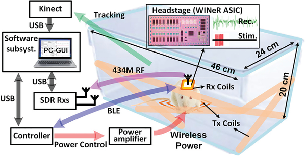
Here we present a new inductively-powered neural recording and stimulation (WINeRS-8) system, which is fully compatible with the EnerCage-HC2 system [26], as shown in Fig. 1. The proposed design is equipped with: 1) 32-ch recording AFE and 4-ch current-controlled stimulation (CCS), 2) bidirectional data communication between 434 MHz on-off keying (OOK) RF transmitter (Tx) and two software defined radio (SDR) receivers (Rx) for wideband uplink data from the headstage [33], 3) wireless power receiver, and 4) Bluetooth Low Energy (BLE) for narrow-band downlink data to the headstage instead of the near-field data communication used in the implantable version of the WINeRS-8 for peripheral nerve recording [34], An implanted device in the animal body typically shows higher coupling between Tx and Rx coils than the headstage because of its proximity to the bottom of the homecage. During the experiment, a Microsoft Kinect® camera performs automated animal tracking and behavior recognition using both 2D color and 3D depth images in real time [35], An overview of the WINeRS-8 system is presented in the following section. WINeRS-8 system architecture is described in section III. The system software is discussed in section IV, followed by in vivo experiment results in section V, and conclusions.
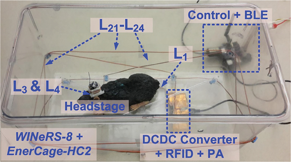
Fig. 1.
A simplified conceptual representation of the proposed inductively-powered wireless neural recording and stimulation (WINeRS-8) system used in a headstage inside the EnerCage-HC2 system for long-term electrophysiology experiments on a freely-moving animal subject (rat).
II. EnerCage-Compatible WINeRS-8 System Overview
Fig. 2 shows a simplified schematic diagram of key building blocks involved in the wireless power and data transfer between the proposed WINeRS-8 headstage and EnerCage-HC2 system. An RFID reader (TRF7960) on the EnerCage-HC2 drives L1 to power the headstage through a 4-coil inductive link inside the standard homecage [26], Wireless power is delivered by a carrier signal at 13.56 MHz, an operating frequency approved by Federal Communications Commission (FCC) for industrial, scientific, and medical (ISM) applications. A CC2540 micro-controller unit (MCU) controls the RFID reader and DC-DC converter via hardwired connection for closed-loop power control. The MCU also sends the setting parameters and stimulation commands to the headstage through a BLE link. When BLE link in the EnerCage-HC2 is not sending the command parameters to the headstage, it is utilized for receiving the monitoring data in the headstage, such as rectifier voltage information for closed-loop power control in this prototype.
Fig. 2.
Schematic diagram of the key building blocks involved in the wireless power and data transmission between the proposed WINeRS-8 headstage, which is a combination of an ASIC and COTS components, and the EnerCage-HC2 system.
The WINeRS-8 headstage is composed of Rx coils, a Schottky rectifier (BAS4002), an Rx MCU (CC2541), and the WINeRS-8 ASIC. Since the WINeRS-8 on-chip LDOs (1 V and 2 V) cannot provide high enough voltage for the MCU, an additional 2.5 V off-chip LDO (MCP1700) is used in the headstage. The WINeRS-8 ASIC includes a 32-ch neural recording AFE, a 4-ch CCS, and three LDOs for 1 V analog, 1 V digital, and 2 V supply voltages. The WINeRS-8 ASIC can be controlled by FWD Data/FWD CK via BLE link to change the recording/RF parameters or perform the stimulation during the operation. Since the BLE link does not have enough bandwidth to carry the recorded raw data from 32-ch AFE, the 434 MHz OOK Tx is implemented in the WINeRS-8 ASIC along with wideband SDR Rx to deliver the recorded data to the PC station. Moreover, a new multi-SDR Rx is utilized to extend the RF coverage over the experimental arena, and demodulate/ unpack the received RF data packet from the WINeRS-8 headstage [33], A graphical user interface (GUI) in the PC provides the control interface of the headstage and data storage/display in real time during the experiment.
III. WINeRS-8 System Architecture
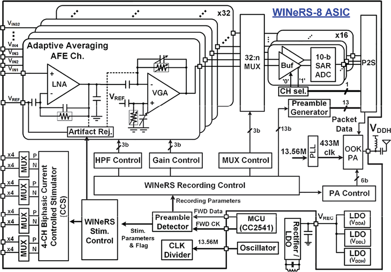
Fig. 3 shows a block diagram of the proposed WINeRS-8 headstage including a WINeRS-8 ASIC that implements 32-ch adaptive averaging AFE, 4-ch CCS with stimulus artifact rejection, digitization, RF Tx, and control blocks.
Fig. 3.
Block diagram of the WINeRS-8 headstage, which is compatible with the EnerCage-HC2 system [26].
Every 2-channels of the AFE share a 50 kS/s 10-bit SAR ADC for digitization depending on ‘CHseΓ bit, resulting in 25 kS/s for each individual channel [36], The digitized data packet includes 13-bit preamble from a preamble generator. It is sent to 434 MHz On-Off Keying (OOK) Tx for uplink data transmission. The carrier frequency of Tx is generated by the internal phase-locked loop (PLL) based on the reference clock of 13.56 MHz. The downlink data from the BLE link is sent to the control block by serial data (FWD Data) and synchronized clock (FWD CK) signals for setting the recording/RF parameters or performing stimulation, depending on two different preambles. The 4-channel CCS is implemented for the positive (P) and negative (N) stimulations, each equipped with individual 4 MUXs. The stimulation flag signal is synchronized by the stimulus artifact rejection signal to prevent the saturation of AFE channels during the stimulation period.
A. DC-Coupled Adaptive Neural Recording AFE with Input Offset Rejection
The 32-ch AFE in WINeRS-8 adopts the adaptive averaging topology, in which a number of AFE channels can be combined by a 32-to-n analog multiplexer (MUX) to reduce the input referred noise of the AFE [36], The effective input referred noise for m-channel combination, Vni_rms,AFE,m, would be,
| (1) |
where m is 32/n, n = 2, 4…32, for the 32-ch neural recording AFE and Vni_rms,AFE,1 for the input referred noise of 1-ch AFE.
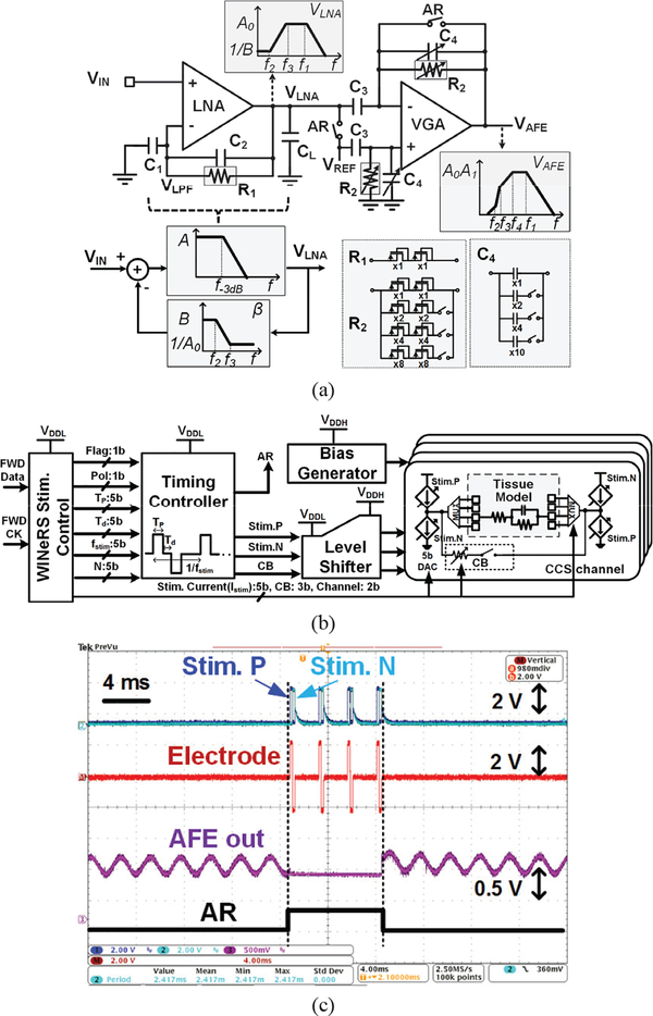
The closed-loop DC-coupled low noise amplifier (LNA) and the variable gain amplifier (VGA) in the AFE channel is shown in Fig. 4a. The LNA has a large open-loop gain of A, and the LNA output, VLNA, is low pass filtered in a feedback loop with feedback gain of β = (1+jwR1C2)/(1+jwR1C1+jwR1C2) and high cut-off frequency of f2= 1/(2πR1C1). Then, the feedback signal, VLPF, is subtracted from the input signal, VIN, after a capacitive attenuator to provide high pass filtering (HPF) and amplification with low cut-off frequency and mid-band gain of f3 = 1/(2πR1C2) and AV,LNA = A0= 1+C1/C2, respectively. The closed-loop LNA transfer function can be expressed as,
| (2) |
Fig. 4.
Schematic diagram of (a) the DC-coupled neural recording AFE with input offset rejection, and bode plot of the AFE blocks and its feedback network, and (b) 4-channel biphasic CCS for closed-loop recording and stimulation, (c) Measurement waveforms of in-situ experiment for biphasic stimulation and stimulus artifact rejection with Randles equivalent tissue model
The AC-coupled VGA is utilized to eliminate the residual DC offset at the electrode-electrolyte interface. The HPF and overall gain of the AFE can be controlled by the downlink data telemetry through BLE link, which digitally adjusts R2 and C4 Therefore, the overall transfer function of AFE can be expressed as,
| (3) |
Both R1 and R2 are implemented using pseudo-resistors to obtain ~GΩ resistance, with R2 being 3-bit adjustable for digital control of the HPF. C4 can be changed by 3-bit gain control according to C3/C4. Specifications of the AFE are summarized in Table I.
Table I.
Recording & Stimulation Interface Specifications
| Parameters | Measured Value |
|---|---|
| Recording Interface | |
| Supply Voltage | 1 V |
| Supply Current | 11 μA/channel |
| LNA Gain | 44 dB |
| VGA Gain | 7.6 dB – 32 dB (3-bits) |
| Low Cut-off Frequency | 20 Hz – 400 Hz (3-bits) |
| High Cut-off Frequency | 15 kHz |
| Input Referred Noise | 3.0 μVrms |
| NEF | 2.95 |
| PSRR | 41 dB |
| Zin @ 1 kHz | 61 MΩ |
| DC rejection | DC-coupled (−0.2V ~ 0.1 V) |
| ADC Sampling Rate | 50 kS/s |
| ADC Resolution | 10 bit |
| Power Consumption | 11.7 μW/channel |
| Stimulation Interface | |
| Preamble | ‘101010101010011’ (15-bit) |
| Polarity (Pol) | Positive/Negative (1-bit) |
| Stim. frequency (fstim) | 13 – 414 Hz (5-bit) |
| Stim. width (Tp) | 9.5 μs – 304 μs (5-bit) |
| Stim. delay (Td) | 9.5 μs – 304 μs (5-bit) |
| Stim. current (Istim) | 60 μA – 1.86 mA (5-bit) |
| Stim. channel | Channel 1 to 4 (2-bit) |
| # of Stim. (N) | 1 – 16 (4-bit) |
| Charge balancing (CB) | 3 bit |
B. Four-Channel Biphasic Current Controlled Stimulator with Stimulus Artifact Rejection
A 4-ch biphasic CCS is included in the WINeRS-8 ASIC. Compared to the voltage controlled stimulation (VCS), CCS shows more reliability in terms of the charge balancing and accurate stimulation control although it provides lower efficiency due to the output voltage of stimulator necessary to drive predetermined current through variable electrode and tissue impedances [37].
Block diagram of the 4-ch biphasic CCS is shown in Fig. 4b, which stimulation parameters are summarized in Table I. The WINeRS-8 stimulation control block receives the FWD Data and FWD CK through the BLE link. When incoming 13-bit preamble matches with the stimulation preamble, the stimulation control block reads those parameters, and sends the recognized 30-bit stimulation parameters to the timing controller and CCS channel with the flag pulse. The timing controller, which includes a series of clock dividers and delay cells, generates the corresponding stimulation pulses, Stim.P and Stim.N, based on the 6 parameters in Table I. Since all of digital controllers are designed for VDDL = 1 V supply to reduce power dissipation mainly in the clock dividers, level shifters are included to drive the CCS operation in higher supply voltage (VDDH), which is more suitable for stimulation. The passive charge balancing (CB) pulse removes the residual charge in the tissue if the positive and negative stimulation pulses are not perfectly balanced. The passive charge balancing method is implemented with a 3-bit controller to limit the amount of current between two electrodes during charge balancing. The stimulation current, Istim, can be controlled by the 5-bit current-steering digital-analog converter (DAC) from 60 μA to 1.86 mA. The 4-ch MUX at the output of the individual CCS can provide the active site selection based on 2-bit control signals.
The timing controller also generates the stimulus artifact rejection pulse during the entire stimulation period to prevent the saturation of AFE channels due to the strong stimulating pulses. The AR pulse, generated by the timing controller in Fig. 4b, forces the LNA output and VGA in the AFE channels to stay at the reference voltage, VDDA/2, through the buffer to enable the recording function of the AFE channels right after the stimulating pulse trains from the CCS. Fig. 4c shows the measurement waveforms of in-situ experiment for the stimulation and stimulus artifact rejection. The Randles equivalent circuit model in [38] is used for the tissue model in this experimental setup. When the stimulation parameters and flag signal are transmitted to the WINeRS-8 stimulation control block, AR signal is generated by the timing controller in the CCS in order to prevent saturation of the AFE from the large stimulus artifact and to enable the recording function after the stimulation. The recovery time of the AFE was less than 0.2 ms in the in-situ experiment.
C. Control Block for Bidirectional Neural Interface
One of the differences between WINeRS-8 system and our prior work in [27] (WINeR-7) is the stimulation function to enable wireless bidirectional neural interfacing, controlled by the PC via bidirectional data transmission. The downlink data telemetry does not need a high data rate to control the stimulation compared to the uplink data telemetry used in transmission of the continuous digitized neural data stream with the data rate of 9 Mbps, as described in section III. Therefore, the BLE link is a suitable method to establish the low data rate communication channel between WINeRS-8 headstage and EnerCage-HC2 system.
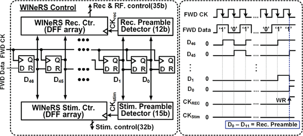
A simplified block diagram of control block in the WINeRS-8 ASIC is shown in Fig. 5 with its conceptual waveforms of the downlink data flow. The transmitted data from the PC is sent to Rx MCU via the BLE link and MCU generates FWD CK and FWD Data. FWD Data is shifted by FWD CK in the data buffer, which consists of 47 D-type flip-flops (DFFs), to detect the “Recording & RF” preamble or “Stimulation” preamble in two different preamble detectors. When the RF preamble matches, CKStim is triggered instead of CKREC to activate the stimulation with the given stimulation parameters as shown in Table I.
Fig. 5.
A simplified block diagram of control block in the WINeRS-8 ASIC with its conceptual waveforms of downlink data flow in the control block.
D. Wideband OOK RF Transmitter
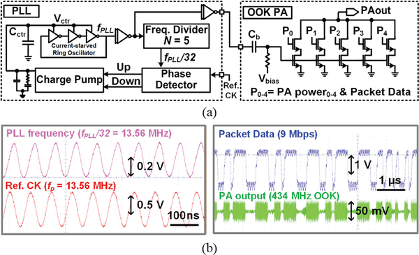
The OOK RF Tx in the WINeRS-8 ASIC is composed of a phase-locked loop (PLL) and OOK power amplifier (PA), as shown in Fig. 6a. A three-stage current-starved ring oscillator is adapted to reduce the supply and temperature sensitivity [39], The ring oscillator structure also has advantages in terms of size and wide tuning range compared to the LC oscillator. The implemented ring oscillator operates up to 1.6 GHz. The generated clock from the ring oscillator is divided by 5-stage DFFs and compared to Ref.CK, provided by an external oscillator, fosc = 13.56 MHz. The charge pump charges/discharges the integration capacitor, Cctr, to control the bias current of the ring oscillator based on ‘Up’/’Down’ pulses from the phase detector, followed by the RC filter for loop stabilization. When the loop is stabilized, the frequency of ring oscillator, fPLL, becomes 32×fosc = 433.9 MHz. The power consumption in the PLL block is 108 μW with 1 V supply voltage.
Fig. 6.
(a) Block diagram of PLL and OOK PA in WINeRS-8 ASIC for wideband RF data transmission, and (b) measured transient waveforms of the PLL and 9 Mbps data stream packet with 434 MHz OOK PA output voltage matched with 50 Ω impedance of the antenna.
The output power of the OOK PA is adjustable with 5-bit resolution, PA power0–4, or 32 levels. The maximum output power of the PA is 0.2 dBm (~1 mW) with the data rate of 9 Mbps. The measured transient waveforms of the PLL and 9 Mbps packet data stream with 434 MHz OOK PA output voltage matched with 50 Ω impedance of the antenna are shown in Fig. 6b.
IV. Software Subsystem of WINeRS-8 and EnerCage-HC2 System
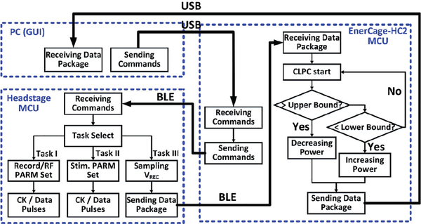
Since two different RF data communication methods are implemented in WINeRS-8 and EnerCage-HC2 system, 1) the bidirectional BLE link for setting the parameters/monitoring data and 2) the uplink wideband RF data through 434 MHz OOK Tx and SDR Rx, the software subsystem of BLE link and RF receivers is required to control the wireless link and properly process the data in real time. Fig. 7 depicts the data communication algorithm between the headstage and EnerCage-HC2 system via the BLE link, implemented in C/C+ in PC and two aforementioned CC2540 and CC2541 MCUs in EnerCage-HC2 and the headstage, respectively. The PC station sends the command to the EnerCage-HC2 MCU through USB connection, and the MCU delivers the command data to the headstage MCU via the BLE link. The headstage MCU receives the command and determines whether the received command is for recording/RF parameter setting, stimulation parameters, or monitoring the headstage, which is VREC sampling in the prototype. In the former case, the headstage MCU generates the proper preamble and data stream is converted into FWD Data and FWD CK, as shown in Fig. 5. In the latter case, the headstage MCU repeatedly samples the VREC and sends it back to the EnerCage-HC2 MCU for the closed-loop power control until the headstage MCU receives another command.
Fig. 7.
Flowchart of the bidirectional data communication link between the WINeRS-8 headstage MCU and EnerCage-HC2 MCU via a BLE link as part of the diagram shown in Fig. 2.
The SDRs provide a flexible RF front end as opposed to a pre-defined hardwired implementation, by providing flexibility in defining the carrier frequency, bandwidth, gain, and modulation method [40], This is why the wideband WINeRS-8 Rx was implemented using a pair of commercially available off-the-shelf (COTS) SDRs, called BladeRF x40 from Nuand (San Francisco, CA) [33], As a receiver, BladeRF offers 300 MHz – 3.8 GHz radio spectrum with full duplex, 12 bit ADC/DAC with 40 MS/s sampling rate, and 40k/115k logic elements in its field-programmable gate array (FPGA) [41].
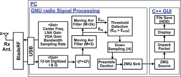
The software subsystem was developed in the GNU radio environment, which is an open-source SDR development tool, widely used in research, education, and proof-of-concept prototype development because it offers many useful signal processing modules [42]. The GNU radio applications are often written in Python programming language. In the WINeRS-8 Rx software subsystem, RF signal processing was performed by the GNU radio and custom routines in C++ for unpacking the recovered data packets and displaying the acquired data in real-time, as shown in Fig. 8. C++ was chosen over Python for its faster runtime and more efficient utilization of the PC resources. The GNU radio sets the parameters of center frequency, RF LNA/VGA gain, bandwidth, and sampling rate of the ADC in the BladeRF.
Fig. 8.
Software subsystem of the wideband WINeRS-8 Rx that is based on a pair of identical software-defined radios (SDR), in charge of the receiving the 434 MHz uplink signal and processing it for data recovery, followed by visualization on the GUI and storage in the PC hard disk (HDD).
The incoming 12-bit digitized I/Q signals, oversampled by 4 times, are converted to magnitude, and 1st moving average filter with M = 3 is applied to reduce noise as the number of points in the filter, M, increases at the cost of the edges becoming less sharp. The 2nd moving average filter of M = 2k is utilized to generate the adaptive threshold for needed for OOK demodulation, which is also an indicator of the average power of the received RF signal. The demodulated OOK data is demultiplexed and sent to GUI software for real-time display of the 32-channel recorded data. In the prototype, the center frequency of SDR is set to 434 MHz with 14 MHz bandwidth, while the ADC in SDR samples the RF signal at 36 MHz. Two SDR receivers were utilized simultaneously in the study to extend the wireless coverage of the experimental arena, and eliminate blind spots caused by the antenna directivity.
V. Acute In Vivo Experimental Results
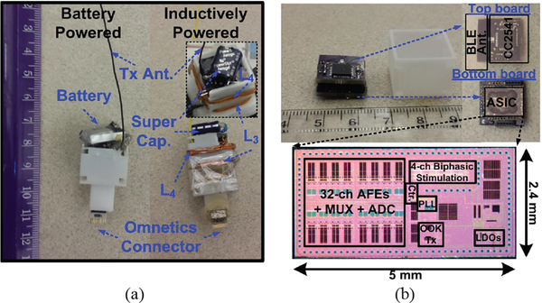
To demonstrate the functionality of the proposed WINeRS-8 system with the EnerCage-HC2 in in vivo experiments, both battery- and inductively-powered WINeRS-8 headstages were designed and constructed, which are shown in Fig. 9a. Fig. 9b shows the main headstage components consisting of two PCBs, WINeRS-8 ASIC, power harvesting unit, and a 3D-printed box. The ASIC was fabricated in 130-nm standard CMOS process, occupying 2.4 × 5 mm2. The overall power consumption of WINeRS-8 ASIC is 18.9 mW, which adds to that of the MCU with built-in BLE, dissipating 16.1 mW at 2.5 V supply voltage. In the inductively-powered headstage, the battery is replaced with a 0.21 F super capacitor to supply the headstage when the received power is interrupted, for instance when there is more than 80° tilting of the headstage or more than 18 cm elevation from the bottom of the homecage. 2.4 GHz PCB antenna was implemented for the BLE link, while a monopole antenna was used for 434 MHz wideband RF Tx. The inductively-powered headstage prototype measures 19 × 19 × 30 mm3 and weighs 5.7 g, including its packaging. A 16-ch Omnetics connector is extended from the bottom of the headstage, and mechanically reinforced with a small magnet, to connect the headstage to implanted electrodes. To maximize PTE inside the EnerCage-HC2, sizes of L3 and L4 were optimized as they were wrapped around the headstage box, as shown in Fig. 9a. All WPT coil dimensions are summarized in Table II.
Fig. 9.
(a) Prototypes of the battery- and inductively-powered WINeRS-8 headstages, and (b) WINeRS-8 headstage key components and the die photo.
Table II.
Specifications of the EnerCage-HC2 Coils on the Homecage (Power Tx) and WINeRS-8 Coils on the Headstage (Power Rx)
| Parameter | L1 | L21 L22 |
L23 L24 |
L3 | L4 |
|---|---|---|---|---|---|
| Inductance (μH) | 5.46 | 2.31 | 1.64 | 0.67 | 1.50 |
| Q-Factor | 116 | 109 | 93 | 143 | 142 |
| Outer diameter (cm) | 13 | - | - | - | - |
| Inner diameter (cm) | 12.8 | - | - | - | - |
| Length (cm) | - | 42 | 23 | - | - |
| Width (cm) | - | 25 | 22 | 1.9 | 1.9 |
| Diameter (mm) | 1.45 | - | - | 0.4 | 0.4 |
| Number of turns | 3 | 1 | 1 | 4 | 6 |
| Type of coil | AWG 15 |
AWG 14 |
AWG 14 |
AWG 26 |
AWG 26 |
| Frequency | 13.56 MHz | ||||
| Nominal distance | 7 cm | ||||
| PTE | 20.5% |
Fig. 10 shows the WINeRS-8 headstage in the EnerCage-HC2 system. A 46 × 24 × 20 cm3 standard rat homecage from Alternative Design (Siloam Springs, AR) was used to construct the EnerCage-HC2, as described in [26], Power Tx coil, L1, and its driver (DC-DC converter + RFID + PA) were located at the bottom of homecage and L21-L24, made of 15-AWG copper wire encompassed it. The driver was covered with copper foils to reduce the high frequency magnetic interference generated from the EnerCage-HC2 system. The power transfer efficiency (PTE) from the EnerCage-HC2 to the headstage was ~20% at 7 cm nominal elevation from the bottom of the homecage.
Fig. 10.
WINeRS-8 proof-of-concept in the EnerCage-HC system. L1 and its driver (DCDC converter + RFID + PA) are located at the bottom of the homecage, and four resonators cover the homecage to power the headstage.
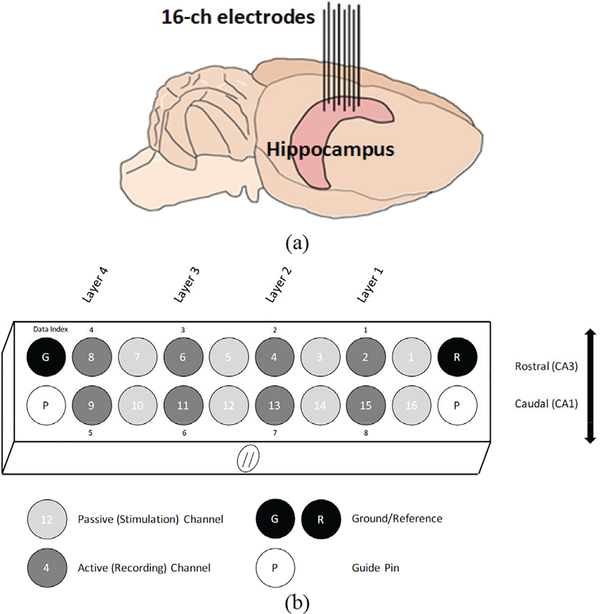
For the in vivo experiment, which was conducted with prior approval from the Institutional Animal Care and Use Committee (IACUC) at Emory University, a Sprague Dawley rat was anesthetized with isoflurane and placed in a stereotactic frame. After confirming the sedation, an incision was made exposing the skull. The head was then adjusted so that cranial suture points, lambda and bregma, were level within 100 μm. Five 2.0 mm stainless steel screws (Plastics One) were affixed to the skull to serve as structural support, as well as reference and ground contacts. An oval craniotomy was then performed with two poles at 2.6 mm ML/2.7 AP and 3.6 mm ML/4.3 mm AP. A 16-channel microelectrode array (MEA) from Tucker Davis Technologies (Alachua, FL) with two rows of eight electrodes, offset by 1 mm, was driven ventral from the pia while continuously recording using a TDT-RZ2 system, as shown in Fig. 11a. The electrodes were driven at 50 μm increments using single unit spiking to ascertain the location of the electrodes within the layers of the hippocampus. This was continued until single units were detected on both the longer and shorter electrodes – approximately 3.5 mm and 2.5 mm ventral from the pia, respectively. These electrodes are customized based on the hippocampus anatomy for simultaneous recording from both CAI (short) and CA3 (long) regions. The reference and ground wires were wrapped around the cranial screws and the surgical opening sealed with dental acrylic.
Fig. 11.
Experimental design of (a) the configuration of the headstage with alternating stimulating and recording electrodes used in the in-vivo experiment and (b) an illustration of the anatomical location of these electrodes within the rat hippocampus.
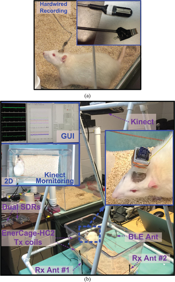
A month following the surgery, the implemented electrodes of the awake and behaving animals were connected to a hardwired commercial headstage (Fig. 12a), as well as battery-and inductively-powered WINeRS-8 headstages within the EnerCage-HC2 system for comparison at different times. Fig. 12b shows in vivo experimental setup for the WINeRS-8 headstage prototype inside the EnerCage-HC2 system with a freely behaving rat. The EnerCage-HC2 continuously delivers 35 mW to the headstage without any interruption while the maximum transmitted power from Tx coil, 2.5 W, is still less than allowable specific absorption rate (SAR) limit, 10.7 W, based on [26] in the worst case of scenario[43]. The electrophysiology signal was bandpass filtered (BPF) between 20 Hz and 300 Hz to obtain the LFP and fair comparison between three different recording methods.
Fig. 12.
In vivo experimental setup for (a) hardwired recording and (b) WINeRS-8 headstage prototype inside the EnerCage-HC2 system. In this experiment, hippocampal multi-electrode array recording was conducted in CAI and CA3.
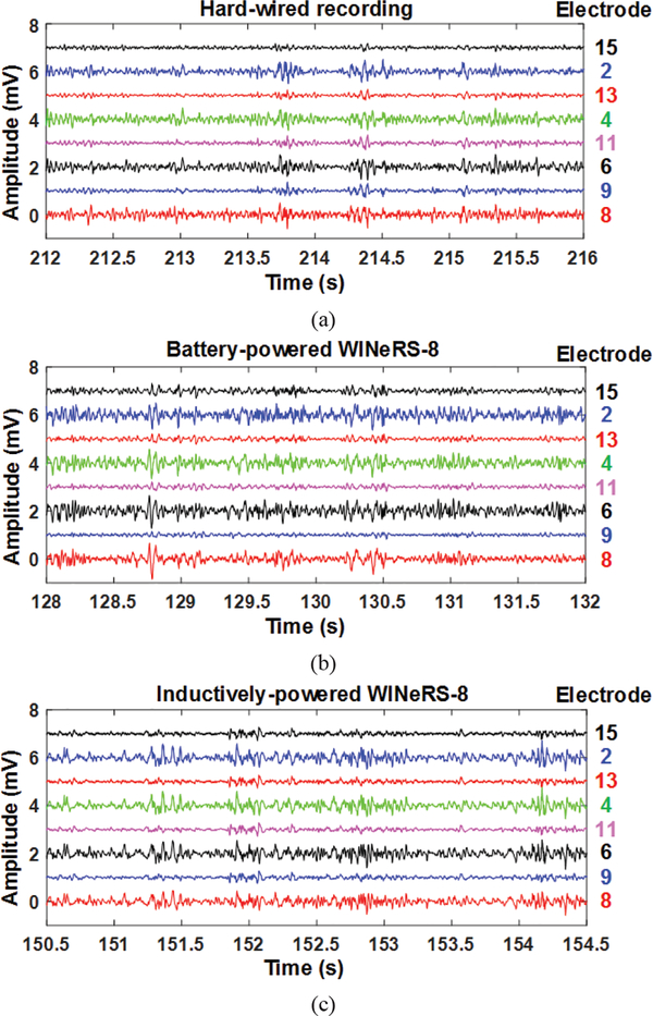
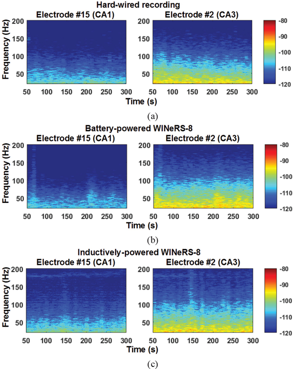
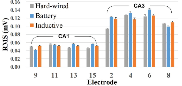
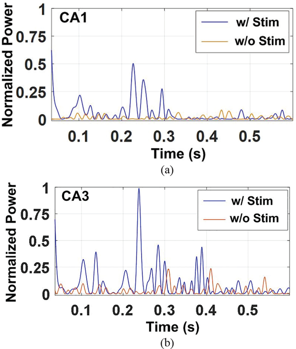
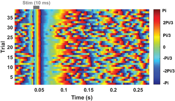
The recorded neural waveforms are compared after applying the same BPF from 20 Hz to 300 Hz. The hardwired, battery-powered WINeRS-8, and wirelessly-powered WINeRS-8 recordings in the EnerCage-HC2 system from the same 8 electrodes are shown in Figs. 13a, 13b, and 13c, respectively. One of the characteristics of these hippocampal multi-electrode array recordings is that the signals from different channels are highly correlated. The spectrograms of the part of recorded signal for ~4 min from randomly selected CAI (electrode #15) and CA3 (electrodes #2) for hardwired recording, battery-powered recording, inductively-powered are shown in Figs. 14a, 14b, and 14c, respectively. The spectrograms from 20 Hz to 200 Hz show similar frequency and power density spectrums in CAI and CA3 regions in these three cases. Fig. 15 shows the RMS amplitudes of LFP for n = 10 samples from CAI (electrodes 9, 11, 13, and 15) and CA3 (electrode 2, 4, 6, and 8) recorded by hardwired, battery-powered, and inductively-powered devices. It demonstrates that WINeRS-8 headstage, inductively-powered by the EnerCage-HC2 system can replace the conventional hardwired or battery-powered recording systems. Figs. 16a and 16b show the normalized power of averaged time-varying LFP for CAI and CA3, respectively, right after the stimulation at t = 0 s. The normalized power spectral density (PSD) within 20~40 Hz in CAI and CA3 regions are integrated for comparison between the stimulated and not-stimulated conditions [44], Higher LFP powers from the stimulations are observed in both CAI and CA3 regions. Fig. 17 shows the instantaneous phase synchronization of the evoked LFPs in 20–100 Hz from 39 trials of 60 μA stimulation, which verifies the electrical stimulation functionality of WINeRS-8 headstage within the EnerCage-HC2 system.
Fig. 13.
LFP recording from (a) the hard-wired system, (b) battery-powered WINeRS-8 system, and (c) inductively-powered WINeRS-8 system with a bandwidth from 20 Hz to 300 Hz.
Fig. 14.
Spectrograms of the recorded signal between 20 Hz and 200 Hz for ~4 min recording from selected CAI and CA3 electrodes, electrode #15 and #2 in Fig. 13 for (a) hard-wired recording, (b) battery-powered WINeRS-8 recording, and (c) inductively-powered WINeRS-8 recording in EnerCage-HC2 system.
Fig. 15.
RMS values of the LPF recorded from CAI and CA3 regions in 10 samples of in vivo experiment conducted by hardwired, battery-powered, and inductively-powered recording.
Fig. 16.
Normalized power of averaged time-varying LFP within 20~40 Hz for (a) CAI and (b) CA3 regions after stimulation (at 0 s), compared to LFP powers without stimulation in inductively-powered WINeRS-8.
Fig. 17.
Instantaneous phase synchronization of recorded LFP signal in 20–100 Hz from electrode #2 evoked by 39 trials of 60 μA electrical stimulation in inductively-powered WINeRS-8.
VI. Discussion
An inductively-powered neural recording and stimulation (WINeRS-8) system, fully compatible with the EnerCage-HC2 system, has been presented for conducting long-term experiment on small freely behaving animals. Table III compares this system with previous works related to wirelessly-powered neural interfaces for preclinical studies. Compared to our own prior work, WINeR-7 [27], WINeRS-8 is a bidirectional interface equipped with electrical stimulation function to be used in closed-loop neuromodulation. A new adaptive averaging method allows users to tradeoff between input referred noise and number of channels, supporting its usage in peripheral nerve interfacing [34], [36], Moreover, higher input impedance, use of SAR ADC, and robust bidirectional wireless data link are among other features in WINeRS-8 that increase its accuracy while reducing power consumption compared to its predecessor.
Table III.
Benchmarking of the Wirelessly-Powered Neural Interfaces
| Parameter | This work | 2017 [26] | 2016 [29] | 2016 [27] | 2017 [45] | 2015 [32] | 2016 [28] | 2016 [30] | 2018 [46] |
|---|---|---|---|---|---|---|---|---|---|
| Power Frequency | 13.56 MHz | 13.56 MHz | 1.5 MHz | 13.56 MHz | 346.6 MHz | 2.3 GHz | 2 MHz | 13.56 MHz | 1.85 MHz |
| Coupling | 4 coil | 4 coil | 2 coil | 3/4 coil | 2-coil | Antenna | 2-coil | 2-coil | Ultrasound |
| Distance (cm) | < 18 | < 20 | < 15 | < 18 | < 18** | < 20 | NA | > 1 | ~0.5 |
| Recording | 32-ch spike | No | 64-ch EEG | 8-ch spike | 1-ch ECG | No | 16-ch EMG | 16-ch LFP | No |
| Stimulation | 4-ch CCS | 1-ch CCS | 64-ch CCS | No | No | 1-ch Opt | 160-ch CCS | No | 1-ch CCS |
| Uplink data | OOK/BLE | BLE | UWB/FSK | FSK | 2.4 GHz RF Tx | No | LSK/WiFi | LSK/BLE | LSK |
| Downlink data | BLE | BLE | ASK | No | No | No | DPSK/WiFi | No | OOK |
| Dimensions (mm3) | 19×19×30 | 20×22×11 | 20×20 | 25×35×8 | 14×25×14 | 38×60×7 | 5×5×5*** | 17×20** | 3.1×1.9×0.89 |
| Power Cons. (mW) | 35 | 43 | 6.9 | 51.4 | 6.4 – 13 | 0.1 | NA | 0.25 | 0.15 |
| PTE | 20.5% | 26.6% | 40% | 27.8% | 5.7% | NA | NA | 73% | 3.4% |
| Weight (g) | 5.7 | 7 | NA | NA | 4.29 | 0.016 | 0.7*** | NA | 0.01 |
| Backpack device | No | No | No | No | No | No | Yes | Yes | Yes |
| Size of Experiment arena (cm3) | 24×46×20 | 24×46×20 | 26×45 | 30×28×18 | 61×61×30 | 30×30 | NA | NA | NA |
| In vivo, freely behaving animal | Yes | Yes | NA* | Yes | Yes | Yes | Yes | No | No |
Experimental setup not described
Estimated
Excluding external backpack device on the animal body
In [28] and [30], the wireless backpacks need to be powered by fairly large batteries. Although this type of neural interface imposes less limitations compared to hardwired setups, duration of the experiment would always be at odds with the bulk of battery, and a limiting factor in design of behavioral experiments. There is an alternative approach in making the device carried by the animal very small, at the cost of forgoing proper control or data communication with the neural interface [32], While this type of devices are good for proof-of-concept demonstrations, they cannot ensure the level of accuracy and reproducibility needed in scientific experiments, and do not inform the user about the status of the device. Previous works in [26], [27], and [45] demonstrated in vivo experiments with wirelessly-powered neural interface on freely behaving animal subjects. However, they could only support a handful of recording or stimulation channels, which does not address todays’ demand in neuroscience community for high-density bidirectional neural interfaces in complex behavioral experiments. Although both recording and stimulation functions with high number of channels are available in [29], the experimental verification on freely behaving animals is missing. Moreover, the AFE in WINeRS-8 has larger bandwidth and lower input referred noise than the ECoG/EEG recording AFE in [29] to be able to support both central and peripheral nerve interfacing applications.
Recently, small (mm-sized) wireless implantable devices are developed that are powered by ultrasound [46], [47], Although the ultrasonic power/data telemetry have advantages in terms of size, weight, and lower interference, particularly for targets that are deeper in the tissue, they inherently suffer from the fact that ultrasound waves are significantly attenuated through air or bones. They are also very sensitive to misalignments and motion artifacts to the extent that to the best of our knowledge no experiment on awake freely behaving animals has yet been conducted.
To minimize the RF interference from the EnerCage-HC2 system, rules of thumb for noise reduction were carefully followed both in RF driver under the homecage and headstage designs. Nonetheless, in Fig. 14 ECoG spectrograms it can be seen that the upper half of Fig. 14a (hardwired) is slightly darker than Fig. 14b (battery-powered), which is in turn somewhat darker than that of Fig. 14c (inductively-powered). This would suggest that the noise is slightly higher in the upper frequency bands of the recorded signals in inductively-powered setup but still well below the desired ECoG signals. In the past we have conducted detailed analysis of various sources of noise in WINeRSoCs [10].
The size and weight of the current headstage prototype, shown in Fig. 9, are higher than desired, particularly for smaller species, such as mice, voles, and songbirds. This is because of the relatively high average power consumption of the headstage (35 mW), which in turn stems from the use of COTS components, such as a general-purpose MCU. It is conceivable and has even been demonstrated that all of these components/functions can be customized and integrated on the same SoC, cutting the power consumption by an order of magnitude or more [31], [49], This will allow us to reduce the size and weight of the next generation of the WINeRS headstage down to below 2 cc and 2 g, respectively, significantly expanding its usage.
The WINeRS-8 combined with the EnerCage-HC2 offer a complete solution for conducting longitudinal behavioral experiments involving bidirectional interfacing with the central (CNS) and peripheral (PNS) nervous systems of small freely behaving animals. However, there is still considerable room for further improvements, such as adding signal processing on-chip for pre-processing, data compression, better artifact rejection, and real-time closed-loop neuromodulation [48], [49], Moreover, now we are at the stage that we can run in vivo studies, not just to demonstrate the system functionality, but to execute actual closed-loop neural interfacing paradigms for evaluating neuroscience research hypotheses and new preclinical neuromodulation strategies.
The WINeRS-8 + EnerCage-HC2 designs have focused on smaller animals, like rodents, because larger animal subjects, such as non-human primates (NHP), porcine, etc. can carry battery-powered wearable or implantable devices fairly easily without biasing their behavior [50], [51], Nonetheless, the EnerCage concept is still applicable to larger animal housing to extend duration of such experiments by recharging batteries without interruption [52], [53].
VII. Conclusion
We have presented an inductively-powered neural recording and stimulation (WINeRS-8) system that is fully compatible with the existing EnerCage-HC2 smart wireless experimental arena for conducting longitudinal electrophysiology and behavioral neuroscience experiments on small freely behaving animals, such as rodents. The WINeRS-8 headstage supports 32-ch neural spike recording and 4-ch biphasic stimulation capabilities for bidirectional neural interfacing. It has wideband RF data transmission for uplink data and BLE for narrow band downlink data, all powered by the EnerCage-HC2 at 13.56 MHz. The complete system functionality was verified in vivo on a freely behaving rat and compared with conventional hardwired and battery-powered systems.
Acknowledgments
This work was supported in part by the NSF awards ECCS-1407880 and ECCS-1408318, and NIH award 1R21EB018561, and by the National Research Foundation of Korea (NRF) grant funded by the Korea government (NRF-2017R1C1B5076814).
Biographies

Byunghun Lee (SΊ1-MΊ7) received the B.S. degree from Korea University, Seoul, South Korea, and the M.S. degree from Korea Advanced Institute of Technology (KAIST), Daejeon, South Korea, in 2008 and 2010, respectively. From 2010 to 2011, he worked on wireless power transfer systems for electric vehicles at KAIST as a research engineer. He also received Ph.D. degree in electrical and computer engineering from Georgia Tech in 2017. Currently, Byunghun Lee is an assistant professor at Incheon National University Department of Electrical Engineering and the director of INU-Wireless Lab.

Yaoyao Jia joined the GT -Bionics Lab in the School of Electrical and Computer Engineering at the Georgia Institute of Technology to pursue her Ph.D. degree in 2014. integrated circuit and system design, wireless power/data transmission, and embedded hardware/firmware design for implantable medical devices and assistive bio-systems. She also worked on power management integrated circuit and power device design during her M.S. in the Department of Microelectronics and Solid-State Electronics at the University of Electronic Science and Technology of China, Chengdu, China. She is the recipient of the IEEE Solid-State Circuits Society (SSCS).

S. Abdollah Mirbozorgi (SΊ0-M’16) received the B.S. degree from the Mazandaran University, Babol, Iran, the M.S. degree from the Ferdowsi University of Mashhad, Mashhad, Iran, and the Ph.D. degree from the Université Laval, Quebec, QC, Canada, all in electrical engineering, in 2008, 2011 and 2015, respectively. From 2015to 2018 he was a postdoctoral research fellow at the GT-Bionics Lab in the School of ECE, Georgia Institute of Technology, Atlanta, GA. Currently, he is an Assistant Professor in the Department of ECE at the University of Alabama at Birmingham, Birmingham, AL.

Xingyuan Tong (M’13) received the Ph. D degree in integrated circuit design from Xidian University, Xi’an, China, in 2011. He joined the Faculty of Xi’an University of Posts and Telecommunications, Xi’an, China, in 2011, where he is currently a professor in the School of Electronic Engineering. From Sept. 2014 to Aug. 2015, he worked as a postdoctoral visiting researcher in the GT-Bionics Lab of Georgia Institute of Technology. His current research interests include analog and mixed-signal integrated circuits, biomedical electronics, low-voltage and low-power analog-to-digital converters.

Maysam Ghovanloo (S’00–M’04–SM’10-F’18) received the B.S. degree in electrical engineering from the University of Tehran, and the M.S. degree in biomedical engineering from the Amirkabir University of Technology, Tehran in 1997. He also received the M.S. and Ph.D. degrees in electrical engineering from the University of Michigan, Ann Arbor, in 2003 and 2004. Dr. Ghovanloo was an assistant professor in the Department of ECE at the North Carolina State University, Raleigh, NC from 2004 to 2007 he. Since 2007 he has been with the Georgia Tech School of Electrical and Computer Engineering, where he is a professor and the founding director of GT-Bionics Lab. He is an Associate Editor of the IEEE Transactions on Biomedical Circuits and Systems, and IEEE Transactions on Biomedical Engineering. He is also serving on the Analog Circuits subcommittee of the Custom Integrated Circuits Conference (CICC).
Contributor Information
Byunghun Lee, School of Electrical Engineering, Incheon National University, South Korea (byunghun_lee@inu.ac.kr)..
Yaoyao Jia, GT- Bionics lab, School of Electrical and Computer Engineering, Georgia Institute of Technology, Atlanta, GA 30308, USA (mgh@gatech.edu)..
S. Abdollah Mirbozorgi, GT- Bionics lab, School of Electrical and Computer Engineering, Georgia Institute of Technology, Atlanta, GA 30308, USA (mgh@gatech.edu)..
Mark Connolly, Department of Physiology, Emory University, Atlanta, GA 30329, USA..
Xingyuan Tong, School of Electronics Engineering, Xi’an University of Posts and Telecommunications, Xi’an, 710121, China..
Zhaoping Zeng, Lixin University, Shanghai, China..
Babak Mahmoudi, Department of Physiology, Emory University, Atlanta, GA 30329, USA..
Maysam Ghovanloo, GT- Bionics lab, School of Electrical and Computer Engineering, Georgia Institute of Technology, Atlanta, GA 30308, USA (mgh@gatech.edu)..
Reference
- [1].Grill WM, Norman SE, and Bellamkonda RV, “Implanted neural interfaces: biochallenges and engineered solutions,” Annual review of biomedical engineering, vol. 11, pp. 1–24, August 2009. [DOI] [PubMed] [Google Scholar]
- [2].Donoghue JP, “Bridging the brain to the world: a perspective on neural interface systems,” Neuron, vol. 60, pp. 511–521, November 2008. [DOI] [PubMed] [Google Scholar]
- [3].Aravanis AM, Wang L, Zhang F, Meltzer LA, Mogri MZ, Schneider MB, and Deisseroth K., “An optical neural interface: in vivo control of rodent motor cortex with integrated fiberoptic and optogenetic technology,” .Journal of neural engineering, vol. 4, p. S143, June 2007. [DOI] [PubMed] [Google Scholar]
- [4].Manns JR and Eichenbaum H, “A congnitive map for object memory in the hippocampus Learning Memory, vol. 16, no. 10, pp. 616–624, September 2009. [DOI] [PMC free article] [PubMed] [Google Scholar]
- [5].Choi Y, Park S, Chung Y, Gore RK, and English AW, “PDMS microchannel scaffolds for neural interfaces with the peripheral nervous system,” Proc. IEEE Micro Electro Mechanical Systems (MEMS) conf, pp. 873–876, January 2014 [Google Scholar]
- [6].Sodagar AM, Perlin GE, Yao Y, Najafi K, and Wise KD, “An implantable 64-channel wireless microsystem for single-unit neural recording,” IEEE J. Solid-State Circuits, vol. 44, no. 9, pp. 2591–2604, September 2009. [Google Scholar]
- [7].Szuts TA, et al. , “A wireless multi-channel neural amplifier for freely moving animals,” Nature Neurosci, vol. 14, no. 2, pp. 263–269, February 2011. [DOI] [PubMed] [Google Scholar]
- [8].Greenwald E, Mollazadeh M, Hu C, Tang W, Culurciello E, and Thakor NV, “A VLSI neural monitoring system with ultra-wideband telemetry for awake behaving subjects,” IEEE Trans. Biomed. Circuits Syst, vol. 5, no. 2, pp. 112–119, April 2011. [DOI] [PubMed] [Google Scholar]
- [9].Fan D, et al. , “A wireless multi-channel recording system for freely behaving mice and rats “ PLoS One, vol. 6, no. 7, pp. 1–9, July 2011. [DOI] [PMC free article] [PubMed] [Google Scholar]
- [10].Lee SB, Yin M, Manns JR, and Ghovanloo M, “A wideband dual antenna receiver for wireless recording from animals behaving in large arenas,” IEEE Trans. Biomed. Eng, vol. 60, no. 17, pp. 1993–2004, July2013. [DOI] [PMC free article] [PubMed] [Google Scholar]
- [11].Harrison RR, Watkins PT, Kier RJ, Lovejoy RO, Black DJ, Greger B, and Solzbacher F, “A low-power integrated circuit for a wireless 100-electrode neural recording system,” IEEE J. Solid-State Circuits, vol. 42, no. 1, pp. 123–133, January 2007. [Google Scholar]
- [12].Guggenmos DJ, Azin M, Barbay S, Mahnken JD, Dunham C, Mohseni P, and Nudo RJ, “Restoration of function after brain damage using a neural prosthesis,” Proc. National Academy Sci, vol. 110, no. 52, pp. 21177–21182, December 2013. [DOI] [PMC free article] [PubMed] [Google Scholar]
- [13].Millard RE and Shepherd RK, “A fully implantable stimulator for use in small laboratory animals,” J. Neuroscience Methods, vol. 166, pp. 168–177, July 2007. [DOI] [PMC free article] [PubMed] [Google Scholar]
- [14].Lenaerts B and Puers R, “Inductive powering of a freely movingsystem,” Sensors and Actuators A: Physical, vol. 123–124, pp. 522–530, March 2005. [Google Scholar]
- [15].Cong P, Chaimanonart N, Ko W, and Young D, “A wireless and batteryless 130mg 300μW 10b implantable blood-pressure-sensing microsystem for real-time genetically engineered mice monitoring”, IEEE Intl. Sym. on Cìrc. & Syst. Conf., pp. 428–429, February 2009. [Google Scholar]
- [16].VitalView Animal Monitoring Products, Starr Life Sciences Corp. [Online]. Available: http://starrlifesciences.com/
- [17].W-series, Triangle Bio Systems Inc., [Online]. Available: http://www.trianglebiosystems.com/
- [18].Wentz CT, Bernstein JG, Monahan P, Guerra A, Rodriguez A, and Boyden ES, “A wirelessly powered and controlled device for optical neural control of freely-behaving animals,” J. Neural Eng, vol. 8, no. 4, pp. 424–436, June 2011. [DOI] [PMC free article] [PubMed] [Google Scholar]
- [19].Lee B, Ahn D, and Ghovanloo M, “Three-phase time-multiplexed planar power transmission to distributed implants,” IEEE J. of Emerging and Select. “Topics in Power Elee, Vol. 4, pp. 263–272, May 2015. [DOI] [PMC free article] [PubMed] [Google Scholar]
- [20].Jow U, McMenamin P, Kiani M, and Ghovanloo M, “EnerCage: a smart experimental arena with scalable architecture for behavioral experiments,” IEEE Trans. Biomed. Eng, vol. 61, no. 1, pp. 139–148, January 2014. [DOI] [PMC free article] [PubMed] [Google Scholar]
- [21].Mirbozorgi SA, Bahrami H, Sawa M, and Gosselin B, “A smart multicoil inductively-coupled array for wireless power transmission,” IEEE Trans. Industrial Electronics, vol. 61, no. 11, pp. 6061–6070, November 2014. [Google Scholar]
- [22].Soltani N, Aliroteh MS, and Genov R, “Cellular inductive powering system for weakly-linked resonant rodent implants,” Proc. of the IEEE Biomed. Cìrc. Sys. Conf, pp. 350–353, October 2013. [Google Scholar]
- [23].Eom K, Jeung J, Lee TH, Kim J, Kim J, Kim J, Lee SE, and Kim SJ, “A wireless power transmission system for implantable devices in freely moving rodents,”Medical & biological engineering & computing, vol. 52, no. 8, pp. 639–651, June 2014. [DOI] [PubMed] [Google Scholar]
- [24].Kilinc EG, Conus G, Weber C, Kawkabani B, Maloberti F, and Dehollain C, “A system for wireless power transfer of micro-systems in-vivo inplantable in freely moving animals,” IEEE Sensors Journal, vol. 14, no. 2, pp. 522–531, February 2014 [Google Scholar]
- [25].Lee B, Kiani M, and Ghovanloo M, “A smart wirelessly-powered homecage for long-term high-throughput behavioral experiments,” IEEE Sensors Journal, vol. 15, issue 9, pp. 4905–4916, September 2015. [DOI] [PMC free article] [PubMed] [Google Scholar]
- [26].Jia Y, Mirbozorgi SA, Wang Z, Hsu CC, Madsen TE, Rainnie D, and Ghovanloo M, “Position and orientation insensitive wireless power transmission for EnerCage-Homecage system,” IEEE Trans. Biomed. Eng, vol. 64, no. 10, pp. 2439–2449, October 2017. [DOI] [PMC free article] [PubMed] [Google Scholar]
- [27].Lee SB, Lee B, Kiani M, Mahmoudi B, Gross R, and Ghovanloo M, “An inductively-powered wireless neural recording system with a charge sampling analog front-end,” IEEE Sensors Journal, vol. 16, issue 2, pp. 475–484, January 2016. [DOI] [PMC free article] [PubMed] [Google Scholar]
- [28].Lo YK, Chang CW, Kuan YC, Culaclii S, Kim B, Chen K, Gad P, Edgerton VR, and Liu W, “A 176-channel 0.5cm3 0.7g wireless implant for motor function recovery after spinal cord injury,” IEEE Intl. Sym. on Cìrc. & Syst. Conf, pp. 382–384, May 2016. [DOI] [PMC free article] [PubMed] [Google Scholar]
- [29].Kassiri H, Bagheri A, Soltani N, Abdelhalim K, Jarari HM, Salam MT, Velazquez JLP, and Genov R, “Battery-less tri-band-radio neuro-monitor and responsive neurostimulator for diagnostics and treatment of neurological disorders,” IEEE J. Solid-State Circuits, vol. 51, no. 5, pp. 1274–1289, May 2016. [Google Scholar]
- [30].Liu X, Zhang M, Xiong T, Richardson AG, Lucas TH, Chin PS, Cummings RE, Tran TD, and Spiegel JV, “A fully integrated wireless compressed sensing neural signal acquisition system for chronic recording and brain machine interface,” IEEE Trans. Biomed. Circuits Syst, vol. 10, no. 4, pp. 874–883, August 2016. [DOI] [PubMed] [Google Scholar]
- [31].Chen WM, et al. , “A fully integrated 8-channel closed-loop neural-prosthetic CMOS SoC for real-time epileptic seizure control,” IEEEJ. Solid-State Circuits, vol. 49, no. 1, pp. 232–247, January 2014. [Google Scholar]
- [32].Park SI et al. , “Soft, stretchable, fully implantable miniaturized optoelectronic systems for wireless optogenetics,” Nature Biotech, vol. 33, no. 12, pp. 1280–1286, December 2015. [DOI] [PMC free article] [PubMed] [Google Scholar]
- [33].Lee B, Jia Y, Kong F, Connolly M, Mahmoudi B, and Ghovanloo M, “Toward a robust multi-antenna receiver for wireless recording from freely-behaving animals,” Proc. IEEE Biom. Cir. & Syst. Conf. (BioCAS), pp. 1–4, October 2018. [Google Scholar]
- [34].Lee B, Koripalli MK, Jia Y, Acosta J, E Sendi MS, Choi Y, and Ghovanloo M, “An implantable peripheral nerve recording and stimulation system for experiments on freely moving animal subjects,” Scientific Reports, vol. 8, pp. 1–12, April 2018. [DOI] [PMC free article] [PubMed] [Google Scholar]
- [35].Wang Z, Mirbozorgi SA, and Ghovanloo M, “An automated behavior analysis system for freely moving rodents using depth image,” Medical & Biological Eng. & Computing, pp. 1–15, 2018. [DOI] [PubMed] [Google Scholar]
- [36].Lee B and Ghovanloo M, “An adaptive averaging low noise front-end for central and peripheral nerve recording,” IEEE Trans. Cir. and Syst. II, vol. 65, no. 7, pp. 839–843, July 2018. [DOI] [PMC free article] [PubMed] [Google Scholar]
- [37].Vidal J and Ghovanloo M, “Towards a switched-capacitor based stimulator for efficient deep-brain stimulation,” Proc. IEEE 32nd Eng. in Med. and Biol. Conf, pp. 2927–2930, August 2010. [DOI] [PMC free article] [PubMed] [Google Scholar]
- [38].Wei XF and Grill WM, “Impedance characteristics of deep brain stimulation electrodes in vitro and in vivo,” J. of Neural Eng, vol. 6, no. 4, pp. 1–9, July 2009. [DOI] [PMC free article] [PubMed] [Google Scholar]
- [39].Zhang X, and Apsel AB, “A low-power, process-and-temperature compensated ring oscillator with addition-based current source,” IEEE Trans. Cir. Syst. I, Reg. Papers, vol. 58, no. 5, pp. 868–878, May 2011. [Google Scholar]
- [40].Abidi AA, “The path to the software-defined radio receiver,” IEEE J. Solid-State Circuits, vol. 42, no. 5, pp. 954–966, May 2007. [Google Scholar]
- [41].BladeRF, [Online]. Available: http://nuand.com/.
- [42].GUN Radio, [Online]. Available: http://gnuradio.org/redmine/projects/gnuradio/wiki/
- [43].W Federal Communications Commission. (2011). Specific Absorption Rate (SAR) for Cellular Telephones [online]. Available at: https://www.fcc.gov/general/specific-absorption-rate-sar-cellular-telephones.2013/ [Google Scholar]
- [44].Jia Y, Khan W, Lee B, Fan B, Madi F, Weber A, Li W, and Ghovanloo M, “Wireless opto-electro neural interface for experiments with small freely behaving animals,” Journal of Neural Engineering, vol. 15, no. 4, 046032 2018. [DOI] [PMC free article] [PubMed] [Google Scholar]
- [45].Mei H, Thackston KA, Bereich RA, Jefferys JGR, Irazoqui PP, “Cavity resonator wireless power transfer system for freely moving animal experiments,” IEEE Trans. Biomed. Eng, vol. 64, no. 4, pp. 775–785, April 2017. [DOI] [PubMed] [Google Scholar]
- [46].Piech DK, Johnson BC, Shen K, Ghanbari MM, Li KY, Neely RM, Kay JE, Carmena JM, Maharbiz MM, and Muller R, “StimDust: A 2.2 mm3, precision wireless neural stimulator with ultrasonic power and communication,” arXiv preprint arXiv:1807.07590, 2018. [Google Scholar]
- [47].Charthad J, Chang TC, Liu Z, Sawaby A, Weber MJ, Baker S, Gore F, Felt SA, and Arbabian A, “A mm-sized wireless implantable device for electrical stimulation of peripheral nerves,” IEEE Trans. Biomed. Circuits Syst, vol. 12, no. 2, pp. 257–270, April 2018. [DOI] [PubMed] [Google Scholar]
- [48].Xu J, Guo H, Nguyen AT, Lim H, and Yang Z, “A bidirectional neuromodulation technology for nerve recording and stimulation “ Micromachines, vol. 9, no. 11, 538, October 2018. [DOI] [PMC free article] [PubMed] [Google Scholar]
- [49].O’Leary G, Groppe DM, Vallante TA, Verma N, and Genov R, “NURIP: Neural interface processor for brain-state classification and programmable-waveform neurostimulation,” IEEE J. Solid-State Circuits, vol. 53, no. 11, pp. 3150–3162, November 2018. [Google Scholar]
- [50].Foster JD et al. , “A freely-moving monkey treadmill model,” J. of Neural Eng, vol. 11, 046020, August 2014. [DOI] [PubMed] [Google Scholar]
- [51].Yin M et al. , “Wireless neurosensory for full-spectrum electrophysiology recordings during free behavior,” Neuron, vol. 84, pp. 1170–1182, December 2014. [DOI] [PubMed] [Google Scholar]
- [52].Piangerelli M, Ciavarro M, Paris A, Marchetti S, Cristiani P, Puttilli C, Torres N, Benabid AL, and Romanelli P, “A fully integrated wireless system for intracranial direct cortical stimulation, real-time electrocorticography data transmission, and smart cage for wireless battery recharge,” Frontiers in neurology, vol. 5, no. 156, pp. 1–5, August 2014. [DOI] [PMC free article] [PubMed] [Google Scholar]
- [53].Powell MP, Britz WR, Jarper JS III, and Borton DA, “An engineered home environment for untethered data telemetry from nonhuman primates,” J. of Neuroscience Method, vol. 288, no. 15, pp. 72–81, August 2017. [DOI] [PubMed] [Google Scholar]


