Abstract
This paper reports the design, modeling, and control of an MR-compatible actuation unit comprising pneumatic stepper mechanisms. One helix-shaped bellows and one toroid-shaped bellows were designed to actuate in pure rotation and pure translation, respectively. The actuation unit is a two degree- of-freedom needle driver that translates and rotates the base of one tube of a steerable needle like a concentric tube robot. For safety, mechanical stops limit needle motion to maximum unplanned step sizes of 0.5 mm and 0.5 degrees. Additively manufactured by selective laser sintering, the flexible fluidic actuating (FFA) mechanism achieves two degree-of-freedom motion as a monolithic, compact, and hermetically-sealed device. A second novel contribution is sub-step control for precise translations and rotations less than full step increments; steady- state errors of 0.013 mm and 0.018 degrees were achieved. The linear FFA produced peak forces of 33 N and −26.5 N for needle insertion and retraction, respectively. The rotary FFA produced bidirectional peak torques of 68 N-mm. With the FFA’s in full motion in a 3T scanner, no loss in signal-to-noise ratio of MR images observed.
Keywords: Magnetic resonance compatible, additively manufactured actuator, flexible fluidic actuator, medical robotics, pneumatic systems, sliding mode control, concentric tube robot, stepper motor
I. INTRODUCTION
Medical robotic systems for image-guided interventions require safe, sterilizable, precision actuators. Imaging modalities like computed tomography (CT) and magnetic resonance imaging (MRI) impose further limitations on actuator design. It is desirable for the robot and its actuators to be transparent to the imager and to not produce artifacts, noise or distortion in the images. Thus, actuator design is restricted to materials and principles of operation that are compatible with the imaging environment. Together with the requirements for safety, sterilizability, and precision control, these restrictions present a challenging design problem. This paper reports an MR-compatible robot to actuate steerable needles using flexible fluidic actuators, and these three fields are briefly reviewed in this introduction.
A. Review of MR-Compatible Robots
Over the past 20 years, numerous custom MR-compatible actuators and robots have been reported in the literature. Due to the high strength magnetic field of the MR imager, these actuators cannot contain ferromagnetic materials. Pneumatic actuation has been commonly employed because the working principle does not rely on electromagnetism. Thus, these actuators can be constructed solely from dielectric materials. Stoianovici et al. reported a pneumatic stepper motor, PneuStep, which consists of three pulsing diaphragms that rotate a harmonic gear drive [1]. Using several of these motors to actuate an MRI-guided robot, Muntener et al. demonstrated transperineal prostate brachytherapy in a canine model [2]. Similarly, using reciprocating piston-cylinders to drive a ratcheting stepper mechanism, Zemiti et al. developed a CT- and MR-compatible needle puncture robot for abdominal procedures [3]. Using both hydraulic and pneumatic piston-cylinders, Van den Bosch et al. reported a momentum-based needle tapping device for prostate interventions [4].
Departing from the stepping mechanism approach, INNOMOTION, one of the few commercially available MRI-guided robotic systems, addressed the need for safety by custom designing pneumatic piston-cylinders to exhibit high dynamic and low static friction [5]. Tokuda et al. demonstrated a needle positioning device employing four pneumatic piston-cylinders, opting for manual needle insertion by the radiologist for safety [6].
Other forms of actuation, in particular piezoelectrics, have been employed in a variety of anatomy-specific MR-compatible robots, including several for neurosurgical procedures [7-9]. While piezoelectrics offer precise, safe, and non-backdrivable actuation, many researchers have reported that the high voltage ultrasonic drivers substantially reduce the signal-to-noise (SNR) ratio of the MR imager, precluding the ability to servo the robot motors while simultaneously acquiring images [5, 7-8, 10]. However, by using low-noise, non-harmonic piezoelectric motors as well as replacing the commercial motor driver boards with custom, low-noise drivers, Su et al. achieved a low loss in SNR of 2% with motors servoing at full speed [11]. For a more comprehensive review of MR-compatible robots, see [8] and [10].
Although piezoelectric actuators can be a viable solution for MR-compatible robots, a low-cost yet customizable actuator that does not require extreme care in the design and shielding of drive electronics is desirable. Furthermore, both pneumatic and piezoelectric robots for MRI-guided interventions as reported in the literature have been limited to linear needle trajectories.
B. Steerable Needles
The objective of this new work is to deploy steerable needles in curved trajectories under MRI guidance using a compact, fail-safe, and sterilizable actuation unit. The MR-compatible actuation unit reported here is designed to robotically control a concentric tube needle, a tentacle-like needle made of multiple, superelastic nitinol tubes with precurved lengths at their tips. Controllable needle motion is realized as the tube bases are rotated and telescoped relative to one another [12-13]. The feasibility of using concentric tube robots has already been investigated for minimally invasive surgeries in open body cavities like the sinuses [14-15]. For soft tissue applications requiring MRI guidance, concentric tube needles would be deployed in a follow-the-leader fashion to prevent tissue damage, as described in [16]. Similarly, bevel tip steerable needles such as described in [17] could also be robotically controlled with our MR-compatible actuation unit. MRI-guided steerable needles would be particularly useful for neurosurgical interventions, because nonlinear needle paths enable avoidance of eloquent, untreated brain tissues, while MRI guidance enables excellent soft tissue visualization and MR thermal imaging (MRTI) enables thermal dosimetry for ablation therapies.
C. Flexible Fluidic Actuator Design and Control
Made of elastomeric diaphragms, bellows, or artificial muscles, flexible fluidic actuators (FFA’s) are an MR-compatible actuation technology. Providing compact actuation with hydraulics or pneumatics as the working fluid, FFA’s are inexpensive and their material compliance often eliminates the need for added spring elements. Early work in the design, modeling, and control of FFA’s was established by Paynter and Wilson and Orgill in [18-20] and [21-23], respectively. Paynter defined models for twisting and translational bellows with changes in enthalpy and experimentally determined torque relationships. Wilson and Orgill developed a mechanics of materials approach for modeling and designing twisting and translating bellows. They and Paynter both demonstrated simple serial and parallel chain robots using bellows actuators, later to be classified as FFA’s by Gaiser et al. [24]. Zientarski and Grzesiak et al. independently reported the use of additive manufacturing of polyamide FFA’s by selective laser sintering (SLS) [25-26]. Grzesiak reported FFA design for additive manufacturing of the Festo Bionic Handling Assistant [26]. Furthermore, novel uses of additive manufacturing processes have been reported to fabricate robotic systems in a cost-effective simultaneous manner, whereby joints, structures, power transmission, and actuators are integrated during the process of fabrication or as a monolithic structure [27-30]. Slightam and Gervasi demonstrated the technology readiness of using selective laser sintering to fabricate monolithic FFA-driven robots in a two level Gough-Stewart platform [31].
A broad range of medical devices have used FFA’s. Proulx and Plante reported an MR-compatible needle positioning device employing binary actuation of 12 pneumatic muscles [32]. Ikuta et al. created a multi-degrees-of-freedom active catheter actuated by miniature saline bellows [33], which were additively manufactured by stereolithography [34]. Similarly, Haga et al. developed a hydraulic suction active catheter and guide wire for intravascular diagnosis and therapy [35]. Further review of fluidic-based medical devices can be found in [36].
While pneumatic FFA’s are an excellent solution for MR-compatibility, in order to achieve precision control it is necessary to accurately model the highly nonlinear pressure and mass flow dynamics. Richer and Hurmuzlu introduced a mathematical model for the gas dynamics and demonstrated substantial improvements in bandwidth and force capabilities using sliding mode control [37-38]. Zhu and Barth achieved sub-millimeter positioning accuracy of 0.05 mm steady-state error using a composite adaptive and sliding mode force controller for an industrial robot [39]. Comber et al. reported sliding mode control of pneumatic piston-cylinders on an MR-compatible concentric tube needle robot, with base joint errors of 0.032 mm and 0.45 degrees resulting in a mean open-loop needle tip error of 1.2 mm [40-41].
In contrast to piston-cylinders, FFA’s offer a hermetically-sealed means of actuation; this is favorable for clinical use because there are no sliding seals at which fluid contaminants can leak. Piston-cylinders are also undesirable due to the risk of full stroke motion in the event of a hardware or software failure. In contrast, a stepping mechanism is fail-safe in the sense that a fault in the pneumatic system will cause no large, unplanned motion of the steerable needle.
The objective of this work was to design, manufacture, and precisely control a fail-safe needle driver for an MRI-guided concentric tube robot. Several of these actuation units can be cascaded together as a complete hardware platform for the robotic intervention.
II. Mechanical Design
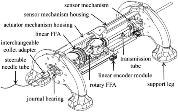
The mechanical design of an MR-compatible, fail-safe actuating device for concentric tube needles is presented in several parts: A) identification of design requirements, B) design to actuate needle translation, C) design to actuate needle rotation, and D) design to transmit power to the needle. Designs of a device housing and position sensor assembly are described as well. The overall approach is to implement FFA design to impart fail-safe, stepper motion to the needle. For reference, a CAD model of the resulting prototype is shown in Fig. 1.
Figure 1.
CAD model of prototype with helix-shaped concentric tube needle.
A. Design Requirements
Specifications were established such that the device would remain safe in the event of a hardware (e.g. mechanical, pneumatic, electrical) failure. Thorough discussions with our clinical collaborator concluded that unplanned needle tip displacements of 0.5 mm and 0.5 degrees were permissible. These limits were thus selected as the maximum step sizes for linear and rotary actuation, in order to make the device fail-safe. The intended clinical application is ablation of the hippocampus (approximately 45 mm long by 18 mm wide) as a minimally-invasive alternative to epilepsy surgery; see [16, 41] for more details.
Actuation forces and torques were determined using prior designs of concentric tube needles; the primary barrier to overcome is the friction that occurs as the telescoping tubes rub against each other. The maximum operating pressure was limited to be no greater than what is commonly supplied by existing instrument air facilities in hospitals. Optical position sensor resolution was chosen to be one order of magnitude greater than the required precision of the robot base joints. Table 1 summarizes these design parameters.
TABLE I.
Device Specifications
| Parameter | Specification |
|---|---|
| Translation step size | 0.5 mm |
| Rotation step size | 0.5 degrees |
| Translation force | 22 N |
| Rotation torque | 100 mN-m |
| Transmission tube diameter | 6.35 mm |
| Needle diameters | 0.75 to 1.5 mm |
| Position sensor resolution | 0.015 mm; 0.020 degrees |
| Stroke length (range of motion) | 75 mm |
| Operating pressure (gage) | 700 kPa |
Ultimately the device needed to provide three principal functions to effectively advance the needle in a sequenced stepping motion: incremental linear displacement, incremental angular displacement, and gripper mechanisms to grasp and release the needle in a non-backdrivable manner. The stepping motion is then accomplished by sequencing control valves located outside the MRI scanner room and connected to the device by long transmission lines. Additionally, a versatile modular design was desirable such that the device could be used for a variety of clinical target applications. Thus, device specifications included adjustability of step size increments as well as the flexibility to interchange tubes across a range of needle diameters.
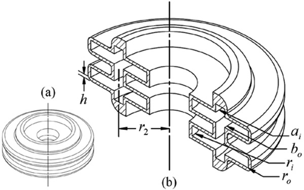
B. Needle Translation
The conceptual design of the actuating mechanism fo translation is illustrated in Fig. 2a and 2b. The linear FFA is made of an inner bellows and outer bellows, connected at their two ends by a thick-wall rigid ring. The resulting hollow center allows for the needle to pass directly through the axial center of the device, achieving a compact design with uniform loading. This design is similar to that of our prior work, but one key difference is that inner bellows clearance was substantially increased [42]. This allows a thick-wall, large diameter tube to run the entire length of the device from back to front. Outside the front housing of the robot module (see Fig 1), this transmission tube steps down to the millimeter-scale needle. Using a collet and clamping nut assembly, the needle can be interchanged for other sizes and shapes of sterilized needle tube. The transmission tube design increases torsional rigidity and reduces the length of expensive nitinol tubing required for the actual needle.
Figure 2.
Diagrams of (a) linear FFA and (b) annotated cutaway view.
Detailed design for the linear FFA began using the analytical model of a flat diaphragm with rigid center as described in [43]. This model is valid for small deflections of magnitudes less than five times the diaphragm thickness. It also assumes linearity between diaphragm displacement and internal pressure, because the rigid center substantially linearizes the diaphragm behavior.
The linear FFA shown in Fig. 2 has some key geometrical differences from a simple flat diaphragm with rigid center. It has a hollow center of radius ri, and inner and outer annular-area diaphragms connected at a radius r2. Thus, the analytical model in [43] was only used as a general guide. It was assumed that the inner and outer annular-area diaphragms each behave as some equivalent flat diaphragm with rigid center. This assumption was made because the rigid region of a rigid-center diaphragm deflects uniformly, and due to geometric constraint, the inner and outer annular diaphragms also deflect equally.
After an initial detailed design was completed using the model in [43], the bellows was drafted in CAD. Then, finite element analysis (FEA) was used to verity the expected displacement of the bellows due to internal pressure loading. FEA revealed a substantial stress concentration in the original design; imbalance between the surface areas of the inner and outer annular diaphragms was determined to be the cause. The location of the corrugation connection r2 was adjusted to reduce this stress concentration.
Accounting for the number of corrugations n that make up the entire bellows, the total displacement Yb, of the linear FFA is given as:
| (1) |
where Y0 is the deflection of just one of the diaphragms. The bellows stiffness kb is then defined by (2), which is a simple force balance equation at equilibrium, where the product of internal pressure and effective acting area Ae is equal to the product of bellows stiffness and displacement. This is Hooke’s Law and assumes linear elasticity. Effective area is less than actual area of the diaphragm because the perimeter of the diaphragm is held stationary and does not deflect; Ae is the ratio of force displaced to applied pressure [43].
| (2) |
The linear FFA was designed for gage pressures from zero to 550 kPa (80 psi) to correspond to deflections from zero to 6 mm, with a linear behavior. While this translation is much greater than the maximum specified step size, the true step size can be adjusted via mechanical stops. Furthermore, this linear deflection range allows for substantial pre-tensioning of the bellows. Pre-tensioning makes the bellows stiffness useful as a restoring force, such that bi-directional actuation is achieved with only one bellows, much like a single-acting piston-cylinder with spring return. The design of a motion constraining system with adjustable mechanical stops and pretension is described in greater detail in Section E. The final design parameters of the linear FFA are listed in Table 2 and meet the specification requirements.
TABLE II.
Linear FFA Design Parameter Values
| Parameter | Value, mm (in) | Parameter | Value |
|---|---|---|---|
| ri | 6.35 (0.250) | n | 2 |
| ro | 22.225 (0.875) | Young’s modulus, E | 1586 kPa (230 ksi) |
| r2 | 14.2875 (0.5625) | Poisson’s ratio, v | 0.408 |
| ai | 13.0175 (0.5125) | kb | 120 N/mm (685 lbf/in) |
| bo | 15.5575 (0.6125) | Ae | 1310.965 mm2 (2.032 in2) |
| h | 0.762 (0.030) |
C. Needle Rotation
FFA’s allow for manipulation of the corrugation geometry to achieve the desired motions in not only translation, but also rotation. The theory of thin orthotropic shells with helical corrugations was well defined by Wilson and Orgill [21-22]. They reported a mechanics of materials approach for the design of helical corrugations on a pressurized thin-walled tube to achieve rotational motion for flexible robotic applications.
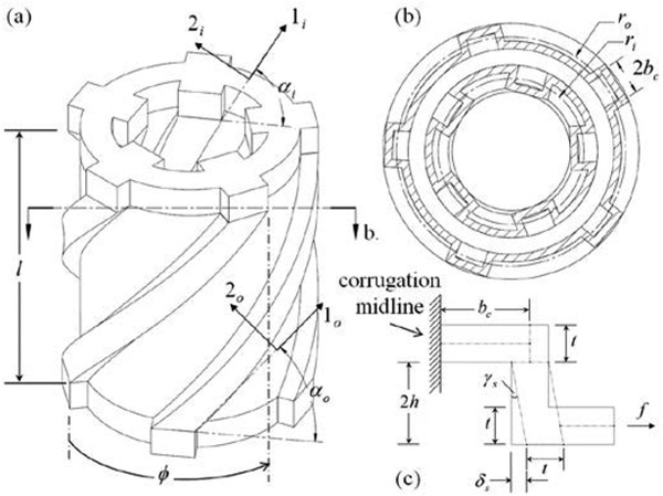
The rotation of the free end of such a tube can be modeled by examining the cross section orthogonal to the central axis of the helices (Fig. 3b). This representation is illustrated in Fig. 3 along with the final computer-aided design (CAD) of the rotary FFA. For a given cross section orthogonal to the 1-axis, the shear displacement δs due to pressurization will occur along the 2-axis direction and can be calculated from the rectangular model shown in Fig. 3c, which resembles the representation reported in [44].
Figure 3.
Diagrams of (a) rotary FFA, (b) cross section orthogonal to central axis, and (c) half corrugation shear deflection.
To design a rotary FFA with helical corrugations, an analytical expression is needed for the cumulative angular displacement θ of the free end of the FFA with respect to the central axis. The rotary FFA geometry as designed in Fig. 3 is unique in that it includes inner helical corrugations at a radius ri. The response of these corrugations to applied pressure is different and is equivalent to pulling a vacuum on the conventional outer corrugations. That is, when pressurized the inner helix “winds up” instead of unwinding. Thus, the inner helix must be given the handedness opposing that of the outer corrugations, in order for angular displacement of the inner corrugations to be in the same direction of rotation as the outer corrugations. The derivation that follows applies to both the outer and inner corrugations, but a minus sign must be included for the inner corrugations. With the inclusion of inner helical corrugations, the overall rotary FFA geometry results in a hollow center that can then be concentric with the axis of the steerable needle and transmission tube.
Referring to Fig. 3c, the shear strain γs of the block of dimensions t by 2h is γs = f /(tG), where f is applied force F per arc length S, t is wall thickness, and G is the shear modulus: . With internal pressurization, the applied force Fo or Fi, acting on one outer or inner corrugation, respectively, is the product of pressure P and total surface area, as given in (3).
| (3) |
The arc lengths So and Si, of the helices are given in (4), where ro is the outer corrugation radius and ri the inner corrugation radius (see Fig. 3b). The outer and inner helix pitches are the same and denoted as p, and the length l of the bellows is l = pφ, where φ is the angular displacement for traveling some longitudinal height l along a helix of pitch p.
| (4) |
By the small angle approximation γs, ≈ tan γs = δs/(2h), δs is then given in (5) as the product of corrugation height 2h and the shear strain of the block in Fig. 3c. Shear displacement is denoted as δs,o for the outer tube and δs,i for the inner tube.
| (5) |
To calculate the cumulative angular displacements θo and θi about the central axis as resulting from δs,o and δs,i respectively, an expression is needed for the pure shear strains γθ o and γθi, relative to the central axis. This expression is obtained by projecting δs from the plane orthogonal to the 1-axis onto the plane of Fig. 3b orthogonal to the central axis. The pure shear strain in units of radians is then obtained by dividing by the radius rs that is tangent to the vector f in Fig. 3c, where rS,o = r0 − h0 and rs,i =ri + hi. The resulting expressions for pure shear strain are given in (6).
| (6) |
Note that a minus sign has been included for the shear strain on the inner corrugations because applied pressure causes the inner helix to wind up, in contrast to unwinding like the outer helix. Table 3 summarizes the four possible corrugation configurations and the corresponding directions of rotation.
TABLE III.
Helical Corrugation Configurations and Resulting Rotations
| Helix Direction | Outer or Inner
Helix |
Rotation Direction |
|---|---|---|
| Clockwise | Outer | Counterclockwise |
| Clockwise | Inner | Clockwise |
| Counterclockwise | Outer | Clockwise |
| Counterclockwise | Inner | Counterclockwise |
Finally, the cumulative angular displacements due to pressure applied to the outer and inner helical corrugations are given in (7). A factor of 2n is included to account for the total number of half-helical corrugations that each undergo the angular strain γθ in a series configuration.
| (7) |
Due to the “winding up” behavior of the inner helical corrugations, a unique characteristic of this rotary FFA design is that the cumulative linear displacement (i.e. along the central longitudinal axis) is quite small. Thus, an FFA exhibiting nearly pure rotation can be realized with this innovative design geometry. As a result of the opposing longitudinal loadings with applied pressure on the inner and outer thin shells, the net longitudinal deflection of the rotary FFA is approximately zero. The cancelation of deflections of the inner and outer helical corrugations is later verified experimentally. Any small amount of net longitudinal deflection that might occur can be eliminated with freely rotating, longitudinal constraints on the free-moving end of the rotary FFA. The final design dimensions for the rotary FFA are specified in Table 4.
TABLE IV.
Rotary FFA Design Parameter Values
| Parameter | Value, mm (in) | Parameter | Value |
|---|---|---|---|
| 2ho | 1.59 (0.0625) | Ae,θ | 1099 mm2 |
| 2hi | 1.97(0.0775) | ro | 11.53 mm |
| t | 0.76 (0.0300) | αo | 49.6 degrees |
| So | 33.36 (1.313) | αi | 61.6 degrees |
| Si | 28.89(1.137) | kθ | 150 kPa/degree |
| ri | 7.33 (0.2888) | n | 5 |
| bc,o | 1.39 (0.0548) | bc,i | 1.57 mm |
D. Needle Grasping
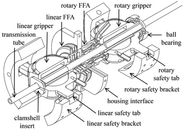
Gripper mechanisms were designed to grasp and release the transmission tube that carries the needle in a non-backdrivable manner. Non-backdrivability is achieved by engaging at least one of the two grippers at all times. Each gripper consists of two diaphragms located on opposing sides of the transmission tube. When inflated, the diaphragms clamp the tube by deflecting toward and making contact with the tube. This design was tested and worked well for imparting actuation from the linear FFA. However, this design was ineffective at imparting actuation from the rotary FFA because the tube slipped in rotation at its line of contact with the gripper diaphragms. This problem was solved by inserting a clamshell-like plastic clamp between the diaphragms and the transmission tube (see Fig. 4). This insert effectively increased the gripping contact surface area and thereby eliminated the unwanted slipping.
Figure 4.
2-DOF actuating mechanism with linear and rotary safety brackets.
E. Device Housing and Constraints
To achieve fail-safe operation for the robot module, linear and rotary safety brackets with mechanical stops were designed. The safety brackets include set screws to adjust the pre-tension on the linear and rotary FFA’s and to adjust the step increment sizes. The brackets were also needed to constrain the linear and rotary FFA motions to pure translation and rotation, respectively, such that the two degrees of freedom remained independent of each other. To accomplish this, rigid constraint tabs were added on both ends of the FFA device, and these tabs interface with linear and rotary safety brackets. As illustrated in Fig. 4, the 2-DOF actuating mechanism includes linear and rotary actuating bellows, two transmission tube grippers, and mechanical constraint tabs.
The constraint tabs are fitted to guide slots in the linear and rotary safety brackets. These brackets are a portion of a larger housing which supports the 2-DOF actuating and position sensing mechanisms. The constraint brackets and mating tabs allow for simultaneous pressurization of the linear and rotary FFA’s. Thus, the step size and pre-tension can be set according to the desired conditions of device operation. This ability to tune the set points for unique procedures, such that step size increments are fail-safe, makes the design robust in its potential for medical applications.
For the linear bellows, the maximum pre-tension length is 1.5 mm and the maximum step increment is 3.5 mm. For the rotary bellows, the maximum pre-tension angle is 0.5 degrees and the maximum step increment is 1.5 degrees. The constraint tabs are sufficiently stiff to handle up to 267 N (60 lbf) of force and 45 N·m (400 lbf·in) of torque applied on the end of the tabs. The tabs could thus handle an unexpected load greater than magnitudes typical of concentric tube robots.
F. Mechanism for Absolute Position Sensing
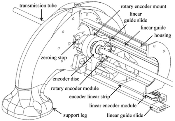
An assembly was designed to provide the absolute linear and rotary displacement of the transmission tube, as shown in Fig. 5. High-resolution, indexed optical encoders were selected to ensure precision feedback and MR-compatibility. The rotary encoder module (U.S. Digital part no. EM2-1-5000-1) is affixed to the rotary encoder mount. This custom part translates with but does not rotate with the transmission tube, because it interfaces with the transmission tube via a ball bearing. A transparent code disc (5000 counts per revolution) mounts to and rotates with the transmission tube. The linear encoder module (U.S. Digital part no. EM1-0-500-I) is affixed to the device housing, while a transparent code strip (500 lines per inch) mounts to the rotary encoder mount and thereby translates with the transmission tube. Two linear guides support the rotary encoder mount and code strip and constrain against angular displacements. For good noise rejection during MRI scanner experiments, a cable driver chip is mounted to each encoder module to convert the signals from single-ended to differential (U.S. Digital part no. PC4-H10).
Figure 5.
Mechanism for sensing transmission tube linear displacement and axial rotation.
G. Device Manufacturing
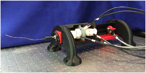
Using tliis mechanical design, a working prototype was manufactured; a photograph appears in Fig. 6. The majority of device components were 3-D printed by fused deposition modeling (FDM) on a Makerbot Replicator 2 in lieu of plastic injected components fabricated with costly tooling. For structural components, the material used was polylactic acid (PLA). The clamshell insert required greater flexibility and was printed in acrylonitrile butadiene styrene (ABS).
Figure 6.
Photograph of the additively manufactured prototype.
Because the 2-DOF actuating mechanism was required to be airtight, it was manufactured using selective laser sintering (SLS). In SLS, a powder bed of build material is fused together layer by layer using a focused laser beam. The powder bed supports the components and allows for the fabrication of freeform geometries that could not be manufactured otherwise [45]. SLS was used because internal features of the FFA’s would not be feasible to manufacture using conventional methods. Additionally, the linear FFA, linear gripper, rotary FFA, rotary gripper, tubes for push-to-connect fittings, safety tabs, and ball bearing hub were all manufactured by SLS as a monolithic, non-assembly structure. The machine used was a 3D Systems Sinterstation 2500 Plus, located at the Milwaukee School of Engineering Rapid Prototyping Center. After the part was printed, un-sintered support material was removed through strategically placed clean-out holes, which then were sealed shut with paraffin wax. This design approach to manufacture integrated fluid power components using SLS is similar to that presented in [46]. Several device components that were commercially available were purchased, including journal bearings, ball bearings, fasteners, and the carbon fiber transmission tube.
The dimensions of the actuation unit are 3.5 inches (8.9 cm) diameter by 13 inches (33 cm) long; this excludes the support legs, which were designed simply to fasten the device to the laser table for benchtop testing. The prototype is sufficiently compact to be positioned along the torso of an adult-sized patient inside a standard diagnostic scanner. Its diameter is 0.4 cm wider than the PneuStep motor [1]; it is 6 cm and 8 cm wider than the pneumatic steppers reported by Sajima et al.[47] and Chen et al. [48], respectively. However, the motor in[48] is limited to unidirectional rotation, and the motors in [1] and [47] do not include a second, translational degree of freedom nor the transmission to manipulate the needle.
III. Controller Design
A novel hybrid controller was designed to meet both the performance criteria for precision positioning and decent speeds for translation and rotation. This control scheme allows for positioning the needle at a finer resolution than full step increments; sub-step control was mentioned by but not demonstrated in [1]. By the sequencing a total of four control valves, the actuating mechanism bi-directionally translates and rotates the transmission tube. Two on/off solenoid valves engage and disengage each respectively one of the two grippers. Two proportional spool valves each respectively control the linear FFA and rotary FFA. Two separate hybrid controllers were designed for translation and rotation control respectively. Each controller has two modes: full step control and sub-step control.
A. Full Step Control Mode
In full step control mode of the linear FFA, the valves are sequenced to advance the transmission tube toward the final desired position. Using three control valves, the following sequence is repeated to advance the tube in the positive direction: (1) Inflate linear gripper, (2) Exhaust rotary gripper, (3) Inflate linear FFA, (4) Inflate rotary gripper, (5) Exhaust linear gripper, and (6) Exhaust linear FFA. To retract the tube in the negative linear direction, the material stiffness of the linear FFA is used to impart a restoring force. The following sequence is repeated to achieve negative linear displacement: (1) Inflate linear FFA, (2) Inflate linear gripper, (3) Exhaust rotary gripper, (4) Exhaust linear FFA, (5) Inflate rotary gripper, and (6) Exhaust linear gripper. The rotary FFA is not active during these two sequences.
In full step control mode of the rotary FFA, the following sequence is repeated to rotate the tube in the positive direction (right-handed) toward the final desired angular displacement: (1) Inflate rotary gripper, (2) Exhaust linear gripper, (3) Inflate rotary FFA, (4) Inflate linear gripper, (5) Exhaust rotary gripper, and (6) Exhaust rotary FFA. The tube is rotated in the negative direction (left-handed) using the internal stiffness of the rotary FFA to impart a restoring torque. The following sequence is repeated to achieve negative angular displacement: (1) Inflate rotary FFA, (2) Inflate rotary gripper, (3) Exhaust linear gripper, (4) Exhaust rotary FFA, (5) Inflate linear gripper, and (6) Exhaust rotary gripper. The linear FFA is not active during these two sequences.
These valve sequences ensure that at least one gripper is engaging the transmission tube (and needle) at all times, for safety.
B. Sub-Step Control Mode
1). Linear FFA Sub-Step Control Law
When the tube displacement is within one step increment of the desired final displacement yref, the controller switches modes from full step control to sub-step control. For linear displacement in sub-step control mode, the linear gripper engages the transmission tube and a model-based, sliding mode controller commands mass flow to the linear FFA using its respective control valve (proportional spool type). The control law formulation has been thoroughly described in our prior work [40, 42]. A brief summary is provided here. The equation of motion for the linear FFA and the final control law to command an orifice area . Av to the spool valve are described by (8) to (14).
| (8) |
| (9) |
| (10) |
| (11) |
| (12) |
| (13) |
| (14) |
In (8), ξ is the bellows’ hysteretic damping and FD represents all the unknown disturbance forces like friction. The control volume V is defined as V = Vdead+ Aey, where the dead volume is Vdead; isothermal behavior is assumed. Model-based sliding mode control is a good choice for precision pneumatic applications because it robustly handles the highly nonlinear dynamics and the unknown friction forces. For this reason, the friction forces and hysteretic damping have been omitted from the control law. The error e is taken as the difference of measured position and reference position, e = y − yref. The functions and g are defined by the companion, or controllability canonical, form of the system dynamics, as given by (10). The mass flow through the proportional valves is given in (11) as normalized by orifice area Av (that is, ṁ = Ψv ) and assumes isentropic flow through a hole in an infmitesimally-thin plate. The pressures upstream and downstream of the valve, Pu and Pd are defined by (12). Isothermal behavior is assumed for the pressure dynamics of the control volume: Ṗ = (RTṁ−PV̇)/V . The sliding surface s and saturation function are defined by (13) and (14), respectively. A summary of the controller parameter definitions and values for the linear FFA is given in Table 5.
TABLE V.
Linear FFA Sub-Step Control Law Parameters
| PARAMETER | Value | Parameter | Value |
|---|---|---|---|
| Gas constant, air, R | 288.3 J/kg/K | Temperature, T | 294 K |
| Robustness constant, η | 200 mm/s3 | Closed-loop poles location, — λ | −120 Hz |
| Hysteretic damping, ξ | 12.5 kPa/(mm/s) | Proportional gain, kp | 0.3 |
| Critical pressure ratio, air, Cr | 0.5286 | Valve discharge coefficient, Cf | 0.2939 |
| Effective area, Ae | 1419 mm2 | Moving mass, M | 82 g |
| C1 for air | 0.04031 s.K0.5/m | C2 for air | 0.1560 s.K0.5/m |
| Boundary layer, φ | 1 mm/s2 | Stiffness, kb | 143 kPa/mm |
2). Rotary FFA Sub-Step Control Law
Similarly, a model-based sliding mode control law was derived for sub-step control with the rotary FFA. The hybrid controller for tube angular displacement switches to sub-step mode when tube angular displacement is within one step increment of the desired final angular position θref . In the equation of motion (15), internal pressurization of the rotary FFA produces torques τo and τi, on the outer and inner corrugations, as given in (16), and τD represents all the unknown disturbance torques like friction. The stiffness and hysteretic damping behaviors are modeled as a torsional spring and damper each acting on some effective area Ae,θ at some effective radius of distance r away from the central axis of the helix. Using the expressions for applied force given in (3), an expression for the quantity rAe,θ is given in (17), where the relation p = ro tan αo = ri, tanαi, is used to simplify.
| (15) |
| (16) |
| (17) |
Using (16) and (17), the equation of motion (15) can be rewritten as (18). The final control law is given by (11)-(14) and (19)-(21). For the sake of simple notation, note that the variables in (15)-(21) are distinct from those of the linear FFA controller in (8)-(10). Definitions and values for new parameters that are different from those in the linear FFA control law are summarized in Table 6. The error is defined as e = θ − θref, and friction and hysteretic damping have been neglected. The control volume is defined as V = Vdead + ΔV, where the change in volume ΔV is given in (21); the displacement θ is obtained by rearranging (6)-(7).
TABLE VI.
Rotary FFA Sub-Step Control Law Parameters
| Parameter | Value | Parameter | Value |
|---|---|---|---|
| Robustness constant η | 2 m/s3 | Closed-loop poles location, — λ | −100 Hz |
| Boundary layer, φ | 1000 m/s2 | Proportional gain, kp | 0.2 |
| Hysteretic damping, ξθ | 93.3 kPa/(deg/s) | Second moment of inertia, J | 16.1 kg-mm2 |
| Stiffness, kθ | 450 kPa/deg | rAe,θ | 8318 mm3 |
| (18) |
| (19) |
| (20) |
| (21) |
IV. Experimental Setup
The prototype was characterized and key performance metrics were quantified using an MRI-compatible testing setup. Pneumatic transmission lines (length 6 m) connect the prototype to non-MRI compatible controller electronics, which are located just outside of the electromagnetically-shielded MRI scanner room. The transmission lines pass through a wave guide port in the shielded wall between the two rooms. Similarly, a low-pass-filtered patch panel at the wall provides D-subminiature connectors for passing the position encoder signals from the scanner room to the controller electronics. Long lengths of double-shielded twisted-pair cables connect the optical encoder modules on the prototype to the patch panel. The controller and data acquisition were implemented using MATLAB Simulink and xPC Target with a sampling rate of 2 kHz.
The pneumatic controls for the prototype consists of two on/off solenoid valves (Festo part no. CPASC1-MH1-M-P-2,5) and two 5-port/3-way proportional spool valves (Festo part no. MPYE-5-M5-010-B). The discharge coefficient for the spool valve is 0.2939. One outlet of the spool valve is plugged and the other outlet connects to the FFA bellows. One pressure transducer provides feedback at the latter outlet (Festo part no. SDE-16-10V) and another transducer measures supply pressure at the valve inlet (Festo part no. SPTW-P10R-G14-VD-M12). For two degrees of freedom, a total of four pressure transducers were used; two separate sensors measured supply pressure at each valve because the linear bellows required 345 kPa gage (50 psi) while the rotary bellows required 620 kPa gage (90 psi) to achieve adequate displacement.
V. Results
A. Bellows Characterization
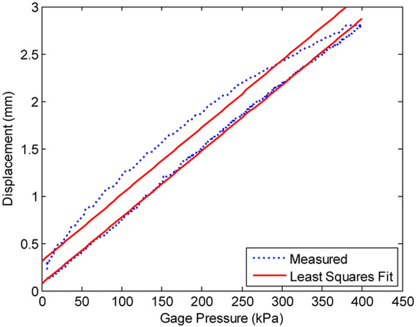
The stiffness and hysteretic damping of the linear and rotary FFA’s were each experimentally characterized. To avoid the transient effect of creep, the linear FFA pressure was very slowly ramped linearly from zero to 400 kPa gage, then quickly exhausted to measure the hysteresis. Plotting the resulting data as bellows displacement vs. pressure gives Fig 7. The stiffness coefficient is the slope of a least squares linear curve fitted to the data and is shown as the lower of the two fitted lines. The y-intercept of this line is near zero as expected. The upper of the two lines has a noticeably non-zero y-intercept and this demonstrates the hysteretic damping. To measure the hysteretic damping, the bellows pressure was quickly depressurized at a rate of 500 kPa/sec. Then the damping coefficient is calculated using (22), where yint is the y-intercept, ymax the initial displacement at maximum pressure, and ω is the rate of depressurization in (mm/sec)/kPa.
Figure 7.
Linear bellows characterization of stiffness and damping.
| (22) |
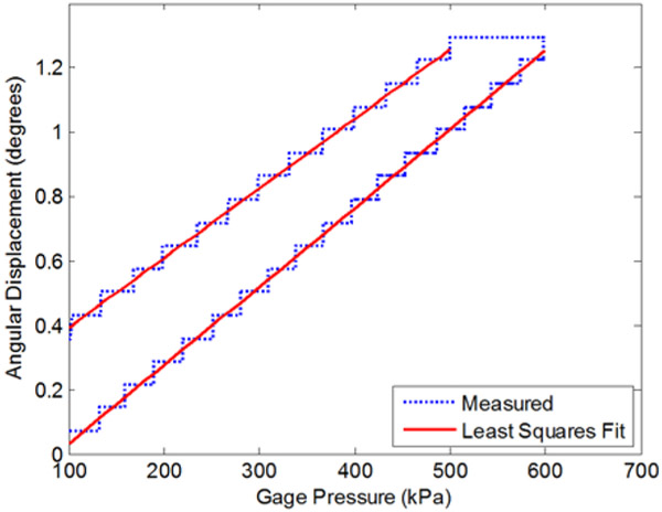
For the rotary FFA the stiffness and damping coefficients were similarly calculated using the data and least square linear fits shown in Fig. 8. The bellows was depressurized from 600 kPa gage to zero at a rate of 600 kPa/sec, and the units of ω are (deg/sec)/kPa. The resulting experimentally determined coefficients are reported in Tables 5 and 6. The rates of depressurization for these measurements were substantially faster than the dynamics expected in operation of the device, and thus the damping coefficients are adequately characterized for the low bandwidth of the controller.
Figure 8.
Rotary bellows characterization of stiffness and damping.
B. Performance Testing
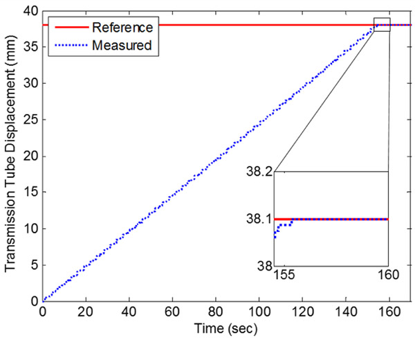
The experimentally determined stiffness coefficients were used with the hybrid controller in positioning experiments to evaluate the controls accuracy. For linear actuation of the transmission tube, the final error was 0.013 mn for the trial run shown in Fig. 9. For the duration of this run, the mean speed of actuation was limited to 0.25 mm/s because the mechanical stops were set to 0.5 mn. Unconstrained by the stops, the linear FFA can move 2.5 mm/s. Additionally, the volume of the 6-meter pneumatic transmission lines increased the total volume by 83%. Thus, the mean speed of actuation can be increased by locating the control valves closer to the actuation unit and by increasing the step increment size.
Figure 9.
Linear positioning of transmission tube with hybrid controller.
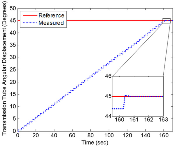
For rotary actuation of the transmission tube, the final error was 0.018 degrees for the trial run shown in Fig. 10. For the duration of this run, the mean speed of actuation was 0.28°/s. However, with the same 6-meter length of transmission lines the rotary hybrid control has been routinely used to rotate at mean speed of 0.5°s and the rotary FFA can move 5°s unconstrained. The mean speed of actuation can be increased in the same ways as were considered for the linear FFA.
Figure 10.
Rotary positioning of transmission tube with hybrid controller.
A force gauge (Extech 475044) was used to measure the maximum force and torque outputs of the actuators. At a gage pressure of 414 kPa, the linear FFA produced forces of +33 N and −26.5 N. At a gage pressure of 755 kPa, the rotary FFA produced torques of 68 mN-m and −68 mN-m. This torque is about 2800%, 45%, and 10% of that of the pneumatic steppers in [48], [47], and [1], respectively.
To verify that the rotary FFA results in purely rotational displacement (i.e. no longitudinal displacement), the linear constraints were removed from the actuation unit and the linear position of the transmission tube was measured during actuation of the rotary FFA. The maximum longitudinal displacement observed across several trials was 0.038 mm, with actuation up to 1 degree of rotation at 480 kPa pressure.
The MR-compatibility of the actuation unit was tested in a 3-Tesla Philips Achieva scanner at Vanderbilt University Institute of Imaging Science (VUIIS). Without the actuation unit present, a baseline image of a liquid phantom was acquired using the same T2-weighted fast spin echo sequence typically used to localize the steerable needle (TR: 3000 ms, TE: 80 ms, 0.5 × 0.5 × 2 mn, 1.5 SENSE). Introducing the prototype, no reduction in signal-to-noise ratio (SNR) was observed with the hardware powered on but not in motion. Even with the hardware in full motion, no observable loss occurred. The SNR was calculated according to the method of [49]. Additionally, the sliding mode control of the prototype was unaffected by the scanner during imaging.
VI. Conclusion
This paper has reported the design, manufacture, and control of a fail-safe, MR-compatible actuation unit to actuate steerable needles. The stepper motion of the device allows for pneumatics to be used in a safer manner than traditional piston-cylinders. The design for additive manufacturing resulted in a compactly integrated prototype that fits inside the MRI scanner with an adult-sized manikin. The novel FFA design used helical bellows with both external and internal pressurization to achieve purely rotational displacements. The actuator produced bi-directional forces and torques of suitable magnitudes for loading with concentric tube needles. An innovative hybrid controller was designed and has demonstrated precision positioning in both translations and rotations of the transmission tube. In-scanner testing with a 3-Tesla machine indicates good MR-compatibility.
This pneumatic actuation unit contributes broadly to the fields of robotics and fluid power by its demonstration of additively-manufactured fluidic actuators and mechanisms. Additive manufacturing served an essential role in designing for a compact footprint and monolithic actuating mechanism, while keeping fabrication costs relatively low. Furthermore, the successful and continuing operation of the prototype for more than one year without any mechanical failures supports the viability of using additive manufacturing to produce functional, end-use devices. The prototype is different from prior work in MR-compatible robots in that it is made of inexpensive, additively manufactured plastic components, and it still provides effective, precision performance.
Acknowledgment
D.B. Comber thanks Philips for personnel support with inscanner experiments conducted at VUIIS. He also thanks Greg Fischer and his lab at Worchester Polytechnic Institute. The authors thank the National Science Foundation Engineering Research Center for Compact and Efficient Fluid Power (CCEFP) for sponsorship of this work under Grant No. EEC-0540834. The authors thank Enfield Technologies and Igus for donations of hardware components.
Manuscript submitted for review March 20, 2015. This work was supported in part by the National Science Foundation Engineering Research Center for Compact & Efficient Fluid Power under Grant No. EEC-0540834.
Biographies

David B. Comber received the B.S. degree from the Pennsylvania State University in electrical engineering, and the M.S. and Ph.D. degrees from Vanderbilt University in mechanical engineering in 2009, 2014, and 2015 respectively. He is currently a postdoctoral research scholar in mechanical engineering at Vanderbilt University, Nashville, TN.
From 2009 to 2010 he was a Facilities Engineer with ExxonMobil Research & Engineering. His current research interests include medical robotics, powered prostheses, MR-compatible devices, fluid power actuator design and control, design for additive manufacturing, and applied nonlinear control.
Mr. Comber received top prize in the 3-in-5 Competition at the ASME Design of Medical Devices Conference, Minneapolis, MN in 2012. He was a Schreyer Honors Scholar and Leonhard Scholar at the Pennsylvania State University from 2005–2009.

Jonathon E. Slightam received the B.S degree in mechanical engineering and M.S. in engineering from the Milwaukee School of Engineering in 2012 and 2014, respectively. He is currently a Ph.D. student in mechanical engineering at Marquette University, Milwaukee, WI.
From 2009 to 2014, he was a research assistant in the Rapid Prototyping Research laboratory at the Milwaukee School of Engineering. In 2013 he was an engineering intern at Parker Hannifin’s hydraulic cartridge systems group in Lincolnshire, IL. His interests are in the modeling, design, and control of flexible fluidic actuators, humanoid robots, and design of efficient mobile robots using additive manufacturing.
Mr. Slightam received an award for his work in the technical competition at the Additive Manufacturing Users Group Conference in 2012.

Vito R. Gervasi earned his B.S. degree in manufacturing engineering technology and M.S. degree in mechanical engineering (materials science) from Milwaukee School of Engineering in 1996 and 2003 respectively. Mr. Gervasi joined the Rapid Prototyping Center research staff as an undergraduate research assistant in 1993 and now directs Rapid Prototyping Research. He has been involved in additive manufacturing for 2 decades and has been leveraging 3-D printing for applied research projects funded by industry and through federal grants. He is an experimentalist at heart with interest in additive manufacturing (including zero G), alternative energy, new product development and aesthetically pleasing designs.

Joseph Neimat received an A.B. degree in music and biochemistry from Dartmouth College, Hanover, NH, in 1992. He completed medical training and a Masters degree in Neurobiology at Duke University, Durham, NC in 1998. Dr. Neimat performed his internship in General Surgery and residency in Neurosurgery at Massachusetts General Hospital, Boston, MA, and completed a fellowship in Functional Neurosurgery at the University of Toronto, Toronto, Canada.
In 2006, he joined the Department of Neurosurgery at Vanderbilt University, where he is currently Associate Professor, and Director of Epilepsy Surgery, Psychiatric Neurosurgery and Adult Neurotrauma. His clinical interests include all aspects of neurological surgery, with emphasis on the treatment of Parkinson’s Disease, the surgical treatment of epilepsy, novel surgical therapies for mental disease, and the multi-modality treatment of trigeminal neuralgia.

Eric J. Barth received the B.S. degree in engineering physics from the University of California at Berkeley, and the M.S. and Ph.D. degrees from the Georgia Institute of Technology in mechanical engineering in 1994, 1996, and 2000 respectively.
He is currently an associate professor of mechanical engineering at Vanderbilt University, Nashville, TN. His research interests include the design, modeling and control of mechatronic and fluid power systems, free-piston internal combustion and free-piston Stirling engines, power supply and actuation for autonomous robots, MRI compatible pneumatic robots, and applied non-linear control.
Contributor Information
David B. Comber, Department of Mechanical Engineering, Vanderbilt University, Nashville, TN 37235 USA, (david.comber@vanderbilt.edu).
Jonathon E. Slightam, Rapid Prototyping Research, Milwaukee School of Engineering, Milwaukee, WI 53202 USA. He is now with the Department of Mechanical Engineering, Marquette University, Milwaukee, WI 53233 USA , (jonathon.slightam@marquette.edu).
Vito R. Gervasi, Rapid Prototyping Research, Milwaukee School of Engineering, Milwaukee, WI 53202 USA, (gervasi@msoe.edu)
Joseph S. Neimat, Department of Neurological Surgery, Vanderbilt University Medical Center, Nashville, TN 37232 USA
Eric J. Barth, Department of Mechanical Engineering, Vanderbilt University, Nashville, TN 37235 USA, (eric.j.barth@vanderbilt.edu)
References
- [1].Stoianovici D, Patriciu A, Petrisor D, Mazilu D, and Kavoussi L, “A New Type of Motor: Pneumatic Step Motor,” IEEE/ASME Trans Mechatronics, 12(1):98–106, 2007. [DOI] [PMC free article] [PubMed] [Google Scholar]
- [2].Muntener M, Patriciu A, Petrisor D, Schar M, Ursu D, Song DY, and Stoianovici D, “Transperineal Prostate Intervention: Robot for Fully Automated MR Imaging—System Description and Proof of Principle in a Canine Model,” Radiology, 247(2):543–549, 2008. [DOI] [PMC free article] [PubMed] [Google Scholar]
- [3].Zemiti N, Bricault I, Fouard C, Sanchez B, and Cinquin P, “LPR: A CT and MR-Compatible Puncture Robot to Enhance Accuracy and Safety of Image-Guided Interventions,” IEEE/ASME Trans Mechatronics, 13(3):306–315, 2008. [Google Scholar]
- [4].Van den Bosch MR, Moman MR, van Vulpen M, Battermann JJ, Duiveman E, van Schelven LJ, de Leeuw H, Lagendjik JJW, and Moerland MA, “MRI-guided robotic system for transperineal prostate interventions: proof of principle,” Phys Med Biol, 55:133–140, 2010. [DOI] [PubMed] [Google Scholar]
- [5].Melzer A, Gutmann B, Remmele T, Wolf R, Lukoscheck A, Bock M, Bardenheuer H, and Fischer H, “Innomotion for Percutaneous Image-Guided Interventions: Principles and Evaluation of this MR- and CT-Compatible Robotic System,” IEEE Eng Med Biol Mag, pp. 66–73, May-Jun 2008. [DOI] [PubMed] [Google Scholar]
- [6].Tokuda J, Song S, Fischer GS, Iordachita II, Seifabadi R, Cho N, Tuncali K, Fichtinger G, Tempany C, and Hata N, “Preclinical evaluation of an MRI-compatible pneumatic robot for angulated needle placement in transperineal prostate interventions,” Int J CARS, 7:949–957, 2012. [DOI] [PMC free article] [PubMed] [Google Scholar]
- [7].Masamune K, Kobayashi E, Masutani Y, Suzuki M, Dohi T, Iseki H, and Takakura K, “Development of an MRI-Compatible Needle Insertion Manipulator for Stereotactic Neurosurgery,” J Image Guid Surg, 1:242–248, 1995. [DOI] [PubMed] [Google Scholar]
- [8].Tsekos N, Khanicheh A, Christoforou E, and Mavroidis C, “Magnetic Resonance-Compatible Robotic and Mechatronics Systems for Image- Guided Interventions and Rehabilitation: A Review Study,” Annu Rev BiomedEng, 9:351–387, 2007. [DOI] [PubMed] [Google Scholar]
- [9].Sutherland G, Latour I, Greer AD, Fielding T, Feil G, and Newhook P, “An Image-Guided Magnetic Resonance-Compatible Surgical Robot,” Neurosurgery, 62(2):286–293, 2008. [DOI] [PubMed] [Google Scholar]
- [10].Fisher T, Hamed A, Vartholomeos P, Masamune K, Tang G, Ren H, and Tse ZTH, “Intraoperative magnetic resonance imaging- conditional robotics devices for therapy and diagnosis,” Proc IMechE Part H: J Engineering in Medicine, 228(3):303–318, 2014. [DOI] [PubMed] [Google Scholar]
- [11].Su H, Cardona D, Shang W, Camilo A, Cole GA, Rucker DC, Webster III RJ, and Fischer GS, “A MRI-Guided Concentric Tube Continuum Robot with Piezoelectric Actuation: A Feasibility Study,” IEEE International Conference on Robotics and Automation, pp. 1939–1945, 2012. [Google Scholar]
- [12].Webster III RJ, Romano JM, and Cowan NJ, “Mechanics of Precurved-Tube Continuum Robots,” IEEE Transactions on Robotics, 25(1):67–78, 2009. [Google Scholar]
- [13].Rucker DC, Jones BA, and Webster RJ III, “A geometrically exact model for externally loaded concentric tube continuum robots,” IEEE Transactions on Robotics, 26(5):769–780, 2010. [DOI] [PMC free article] [PubMed] [Google Scholar]
- [14].Burgner J, Rucker DC, Gilbert HB, Swaney PJ, Russell III PT, Weaver KD, and Webster III RJ, “A Telerobotic System for Transnasal Surgery,” IEEE/ASME Transactions on Mechatronics, 19(3):996–1006, 2014. [DOI] [PMC free article] [PubMed] [Google Scholar]
- [15].Swaney PJ, Gilbert HB, Webster III RJ, Russell III PT, and Weaver KD, “Endonasal Skull Base Tumor Removal Using Concentric Tube Continuum Robots: A Phantom Study,” Journal of Neurological Surgery Part B: Skull Base, In Press. [DOI] [PMC free article] [PubMed] [Google Scholar]
- [16].Gilbert HB, Neimat J, and Webster RJ III, “Concentric Tube Robots as Steerable Needles: Achieving Follow-the-Leader Deployment,” IEEE Trans Robotics, 31(2):246–258. [DOI] [PMC free article] [PubMed] [Google Scholar]
- [17].Webster III RJ, Kim JS, Cowan NJ, Chirikjian GS, and Okamura AM, “Nonholonomic Modeling of Needle Steering,” Int. J. Robotics Research, 25(5–6):509–525, 2006. [Google Scholar]
- [18].Paynter HM, “Low-Cost Pneumatic Arthrobots Powered by Tug-&- Twist Polymer Actuators,” Japan/USA Symposium on Flexible Automation, 1:107–110, 1996. [Google Scholar]
- [19].Paynter HM, “Thermodynamic Treatment of Tug-&-Twist Technology: Part 1 - Thermodynamic Tugger Design,” Japan/USA Symposium on Flexible Automation, 1:111–117, 1996. [Google Scholar]
- [20].Paynter HM and Juarez JM, “Thermodynamic Treatment of Tug-&- Twist Technology: Part 2 - Thermodynamic Twister Design,” IEEE/ASME Int Conf Advanced Intelligent Mechatronics, 1999. [Google Scholar]
- [21].Wilson JF and Orgill G, “Linear Analysis of Uniformly Stressed, Orthotropic Cylindrical Shells,” ASME J Applied Mechanics, 53(2):249–256 1986. [Google Scholar]
- [22].Orgill G and Wilson JF, “Finite Deformations of Nonlinear, Orthotropic Cylindrical Shells,” ASME J Applied Mechanics, 53(2):257–265, 1986. [Google Scholar]
- [23].Wilson JF, “Mechanics of fluid-activated, clustered satellite bellows,” Int J Solids Structures, 45:4173–4183, 2008. [Google Scholar]
- [24].Gaiser I, Schulz S, Breitwieser H, and Bretthauer G, “Enhanced Flexible Fluidic Actuators for Biologically Inspired Lightweight Robots with Inherent Compliance,” Proc IEEE Int Conf Robotics Biomimetics, pp. 1423–1428, Tianjin, Dec 2010. [Google Scholar]
- [25].Zientarski S, “Additive Manufacturing of Fully Functional Fluid Power Components,” Proc. NCUR, 2010. [Google Scholar]
- [26].Grzesiak A, Becker R, and Verl A, “The Bionic Handling Assistant: a success story of additive manufacturing,” Assembly Automation, 31(4):329–333, 2011. [Google Scholar]
- [27].Rajagopalan S and Cutkosky MR, “Tolerance Representation for Mechanism Assemblies in Layered Manufacturing,” Proc ASME Design Engineering Technical Conference, pp. 1–10, Sept 1998, Atlanta. [Google Scholar]
- [28].Won J, DeLaurentis KJ, and Mavroidis C, “Fabrication of a Robotic Hand using Rapid Prototyping,” Proc ASME Design Engineering Technical Conference, pp. 1–7, Sept 2000, Baltimore. [Google Scholar]
- [29].DeLaurentis KJ and Mavroidis C, “Rapid Fabrication of a Non-assembly Robotic Hand with Embedded Components,” Assembly Automation, 24(4):394–405, 2004. [Google Scholar]
- [30].Lalibert T and Gosselin CM, “Practical Prototyping,” IEEE Robotics Automation Magazine, September 2001. [Google Scholar]
- [31].Slightam JE and Gervasi VR, “Novel Integrated Fluid-Power Actuators for Functional End-Use Components and Systems via Selective Laser Sintering Nylon 12,” 23rd Ann Int Solid Freeform Fabrication Symp, pp. 197–211, 2012, Austin. [Google Scholar]
- [32].Proulx S and Plante J, “Design and Experimental Assessment of an Elastically Averaged Binary Manipulator Using Pneumatic Air Muscles for Magnetic Resonance Imaging Guided Prostate Interventions,” J Mech Des, 133(11):1–9, 2011. [Google Scholar]
- [33].Ikuta K, Hironobu I, Katsuya S, and Takahiro Y, “Micro Hydrodynamic Actuated Multiple Segments Catheter for Safety Minimally Invasive Therapy,” Proc IEEE Int Conf Robot Automat, pp. 2640–2645, 2003. [Google Scholar]
- [34].Kang H-W, Lee IH, and Cho D-W, “Development of a micro-bellows actuator using micro-stereolithography technology,” Microelect Eng, 83(7):1201–1204, 2006. [Google Scholar]
- [35].Haga H, Matsunaga T, Makishi W, Totsu K, Mineta T, and Esashi M, “Minimally Invasive Diagnostics and Treatment using Micro/Nano Machining,” Minimally Invasive Therapy, 15(4):218–225, 2006. [DOI] [PubMed] [Google Scholar]
- [36].De Greef A, Lambert P, and Delchambre A, “Towards Flexible Medical Instruments: Review of Flexible Fluidic Actuators,” Precision Engineering, 33(4):311–321, 2009. [Google Scholar]
- [37].Richer E and Hurmuzlu Y, “A High Performance Pneumatic Force Actuator System: Part I—Nonlinear Mathematical Model,” ASME J Dyn Syst, Meas Control, 122(3):416–425, 2000. [Google Scholar]
- [38].Richer E and Hurmuzlu Y, “A High Performance Pneumatic Force Actuator System: Part II—Nonlinear Controller Design,” ASME J Dyn Syst, Meas Control, 122(3):426–434, 2000. [Google Scholar]
- [39].Zhu Y and Barth EJ , “Accurate Sub-Millimeter Servo-Pneumatic Tracking using Model Reference Adaptive Control (MRAC),” Int J Fluid Power, 11(2):49–57, 2010. [Google Scholar]
- [40].Comber DB, Barth EJ, and Webster RJ III, “Design and Control of an MR-Compatible Precision Pneumatic Active Cannula Robot,” ASME J Medical Devices, 8(1):011003-1–7, 2014. [Google Scholar]
- [41].Comber DB, Webster III RJ, Neimat JS, and Barth EJ, “Open-Loop Tip Accuracy of an MRI-Compatible Active Cannula Robot,” Proc. Hamlyn Symp Medical Robotics, pp. 112–113, Jun 2013, London. [Google Scholar]
- [42].Comber DB, Slightam JE, Gervasi VR, Webster III RJ, and Barth EJ, “Design and Precision Control of an MR-Compatible Flexible Fluidic Actuator,” Proc. ASME/Bath Symposium on Fluid Power & Motion Control, pp. 1–9, 2013, Sarasota, FL. [Google Scholar]
- [43].Di Giovanni M, 1982, Flat and Corrugated Diaphragm Design Handbook, Marcel Dekker, New York, pp. 130–192. [Google Scholar]
- [44].Wilson JF and Inou N, “Bellows-Type Springs for Robotics,” Proc. of Advanced Spring Technology JSSE 60th Anniversary Int. Symposium, pp. 109–119, Nov 2007, Nagoya, Japan. [Google Scholar]
- [45].Gibson I, Rosen DW , and Stucker B, 2010, Additive Manufacturing Technologies: Rapid Prototyping to Direct Digital Manufacturing, Springer, New York, pp. 107–133. [Google Scholar]
- [46].Slightam JE and Gervasi VR, “Additively Manufactured Flexible Fluidic Actuators for Precision Control in Surgical Applications,” 24th Ann Int Solid Freeform Fabrication Symp, pp. 777–790, 2013, Austin. [Google Scholar]
- [47].Sajima H, Kamiuchi H, Kuwana K, Dohi T, and Masamune K, “MR- safe pneumatic rotation stepping actuator,” Journal of Robotics and Mechatronics, 24(5):820–827, 2012. [Google Scholar]
- [48].Chen Y, Mershon C, and Tse ZTH, “A 10-mm MR-Conditional Unidirectional Pneumatic Stepper Motor,” IEEE/ASME Trans. Mechatronics, 20(2):782–788, 2015. [DOI] [PMC free article] [PubMed] [Google Scholar]
- [49].Chinzei K, Kikinis R, and Jolesz FA, “MR compatibility of mechatronic devices: design criteria,” Medical Image Computing and Computer-AssistedIntervention-MICCAI, pp. 1020–1030, January 1999. [Google Scholar]


