Abstract
Magnetic Resonance (MR) guided interventional robots have recently been developed for a variety of surgeries, such as biopsy, ablation, and brachytherapy. The actuators and encoders that power and track such robots must be MR-conditional. In this paper, we propose an MR-conditional pneumatic motor with an integrated and custom-built fiber-optical encoder that provides powerful and accurate actuation. The motor is coupled with a modular plastic gearbox that provides a variety of gear ratio options so that the motor can be adapted to application requirements. With a 100:1 gear reduction at 0.55 MPa, the motor achieves 460 mNm stall torque and 370 rpm no-load speed, which leads to the peak output power of 6W. The motor has the bandwidth of approximately 1.1 Hz and 3.5 Hz when connected to 8 m and 0.2 m air hoses, respectively. The motor was tested in a 3T MRI scanner. No image artifact was observed and maximum signal to noise ratio (SNR) variation was less than 5%. Different from most of the existing MR-conditional pneumatic actuators, the proposed motor shape is more like the traditional electric motors, which offers more flexibility in the MR-conditional robot design.
Keywords: Magnetic Resonance Imaging (MRI), MR-conditional, pneumatic motor, optical encoding
I. Introduction
WITH the advancement of magnetic resonance imaging (MRI), MR-guided robotic therapy is a growing technology [1]. In the past few decades, MR-conditional (see next paragraph for definition) robot technology has been extensively studied by both medical and robotic communities due to its advantages over computed tomography (CT), ultrasound (US) and positron emission tomography (PET) guided therapies, such as high-resolution soft tissue imaging, lack of ionizing radiation, accurate ablation temperature monitoring, and intraoperative surgical outcome evaluation [2]. To date, MRI-guided surgical interventions have been used in the prostate intervention [3], breast biopsy [4], stereotactic neurosurgery [5], and cardiac catheterization [6] among surgical and diagnosis applications.
One of the major challenges in designing robotic systems for the MR scanner environment is the fact that the strong magnetic field precludes the use of actuators made of ferromagnetic or paramagnetic materials. The American Society for Testing and Materials [7] classify interventional systems such as robots, surgical devices, and implants into three categories: MR safe, MR-conditional, and MR unsafe based on their interaction with MR scanners. MR-safe devices must pose no known hazards across all MR environments, while MR-conditional devices pose no known hazards in a specified MRI environment with specified conditions of use.
The majority of the MR-guided robotic systems designed to date employ MR-conditional piezoelectric motors [8, 9]. A drawback to these motors is that they should not be in motion during image acquisition, because the electric power used can distort static magnetic fields and field gradients, adversely affecting image quality [10]. For instance, harmonic [8] and nonharmonic [9] piezoelectric motors within an MR scanner can reduce the signal to noise ratio (SNR) up to 80% and 26% respectively. The decoupled imaging and robotic operation can sometimes adversely affect the surgical workflow [11]. Recent innovations show that better image quality can be achieved, but custom designed piezo actuator driver and control system are required [12]. Alternatively, hydraulic actuation can be used for powering MR-conditional robots but drawbacks include potential fluid leakage, large inertia, and potential safety concerns [13].
In contrast, pneumatic actuation is clean, safe, and electromagnetically decoupled from MR scanner [14]. A pneumatic air supply is typically available in MR scanner facilities. In comparison to hydraulic actuation, pneumatic actuation is safe even when air leakage happens inside the scanner due to low operating pressures. With the advancement of additive manufacturing techniques, MR-conditional pneumatic actuators can be easily tailored with plastic materials for different applications. Pneumatic pistons [15] and motors [16] are the two main types of actuation methods employed in MR-conditional applications. Pneumatic pistons have been shown to achieve submillimeter linear motion tracking accuracy [17] but require additional transmission to obtain rotational motion. PneuStep, proposed by Stoianovici, was the first pneumatic stepper motor used in MR-guided robotic interventions [16]. Following Stoianovici’s pioneering work, Bosboom [18], Sajima [19], Chen [20], Groenhuis [21] and Guo [22] developed several different stepper motors. In addition, Secoli [23] and Chen [24] developed MR-conditional step mechanisms based on camshaft principles. Comber et al. designed flexible fluidic stepper actuators and achieved accurate linear and angular motion [25]. The desire for a design more like a traditional motor than [24, 25] and one that does not require high-resolution fabrication processes like [16, 18], motivates the work in this paper.
In this paper, we propose a new MR-conditional pneumatic motor with a built-in MR-conditional optical encoder. The characteristics of this motor are 1) simple continuous (non-stepwise) actuation; 2) compact optical encoder; 3) low-cost additive manufacturability and; 4) ability to integrate with off the shelf modular plastic gearboxes to meet desired application requirements. This motor addresses the limitations of a previous design [26] by optimizing the rotor mechanical design to prevent potential miscounting and reduce fabrication cost through a binary encoding method. In addition, this paper conducts a complete dynamic characterization and closed loop control experiments with the proposed pneumatic motor. The paper is arranged as follows. Section II presents the working principles of the motor, encoding technique and bi-directional control algorithm. Section III describes the characterization results and closed-loop control performance followed by Conclusions in section IV.
II. Materials and Methods
A. Design Overview and Working Principle
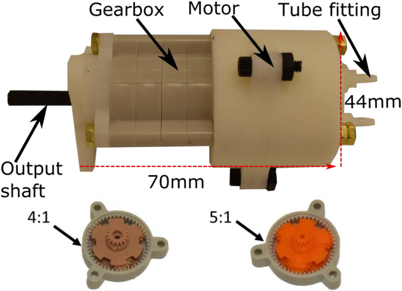
Fig. 1 shows a prototype of the proposed MR-conditional pneumatic motor coupled with a planetary gearbox. The actuation unit (∅44mm × 37mm) has three main components: the stator, rotor, and cap. It is constructed using a Stratasys Dimension SST 3D printer (0.254 mm resolution) using acrylonitrile butadiene styrene (ABS). The motor is encoded by a set of optical fibers. A modular plastic planetary gearbox (Tamiya no. 72001) is coupled to the pneumatic motor. Individual gear modules (∅28mm × 7.5mm) are available in 4:1 or 5:1 ratios and multiple stages can be combined to obtain various gear ratios (e.g., 5:1, 20:1, 100:1, etc.) to meet different torque and speed requirements. The gearbox is connected to the motor housing through brass threaded rods. The mechanical and magnetic properties of these materials guarantee mechanical strength, durability, reliability, and MR-safety of the motor. One may custom design a gearbox in order to further reduce the motor assembly dimension. The detailed fabrication method and construction materials of the proposed motor are summarized in Table 1.
Fig. 1.
Assembly of the proposed pneumatic motor coupled with a gearbox. The modular gear stages shown at the bottom are available in 4:1 and 5:1 gear ratios.
Table 1.
Fabrication and materials of the proposed motor
| Item | Fabrication technique/Vendor | Material |
|---|---|---|
| Motor, rotor & cap | 3D printer | ABS |
| Large Bearings | VXB Bearings Inc. | Polyamide and glass |
| Small bearing | Igus Inc. | Polyamide and glass |
| Gearbox | Amazon | Nylon |
| Optical encoder unit | i-fiberoptics.com | Polymer |
| Accessories (Φ3mm thread rod, nut) | McMaster Inc. | Brass |
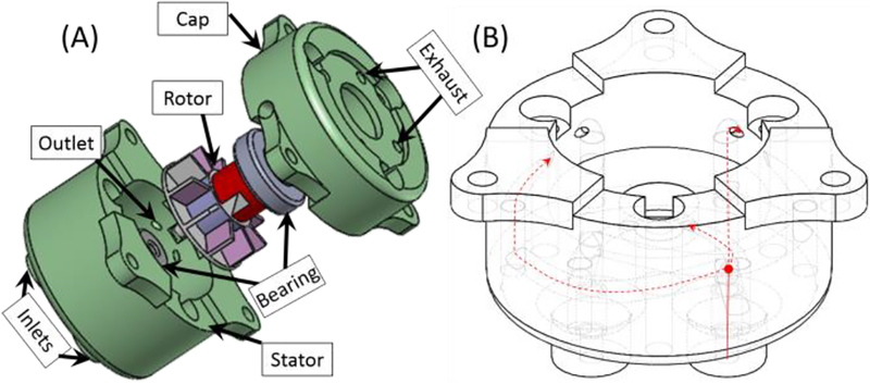
The operation principle of the pneumatic motor is illustrated in Fig. 2. Unlike conventional pneumatic motors, the rotor is a modified Pelton turbine [27] for bi-directional operation. Compressed air is supplied to the two inlets located at the bottom of the motor housing. Each inlet channel has three outlets within the housing, which are separated by 120° about the turbine axis. The pressurized air, routed through the channels and directed onto the turbine blades through the outlets, pushes the turbine blades and generates rotary motion in either direction depending on which inlet the air is supplied to. The excess air is released to the surroundings through the exhaust ports.
Fig.2.
(A) Exploded view of the motor assembly. The actuation unit includes stator, rotor, and cap. The rotor is supported by two plastic bearings to reduce friction, (B) Illustration of airflow channels inside the stator. The compressed air provided at the inlet (solid red line) is divided into three channels (dashed red line), which is terminated at the inner wall aiming the turbine blades. Motor rotation direction is reversed by changing the inlet to which the compressed air supplied.
B. MR-conditional Encoding
Traditional optical encoders introduce electricity into the scanner and can compromise image quality [15]. Radio-frequency (RF) shielding of encoders and electric cables can reduce the distortion but increases system complexity. In addition, the dimensions of encoder modules increase the overall size of actuation units which can be problematic given the confined space within the MR scanner. Active RF micro tracking coils (8mm × 1.5mm) can be used to obtain task- space feedback with a tracking resolution down to 0.6mm × 0.6mm × 0.6mm at 40 Hz [28]. However, an MR active tracking sequence must be designed and programmed into the MR scanner to read the spatial information of these tracking coils.
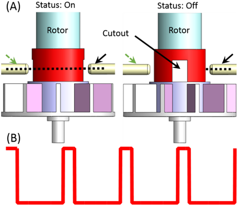
To provide a compact and simple approach to encoding, we designed the built-in MR-conditional encoder, as shown in Fig. 3. The 8-meter optical fiber carries a continuous light beam from the control room across the pneumatic motor. The light beam is interrupted cyclically due to the rotor rotation. In our previous design [26], the large distance between the sender and receiver optical fibers (determined by a rotating block) resulted decreased the optical signal intensity and led to potential risks of miscounting in practical applications. In addition, the undesired unbalanced mechanical design generated large noise and vibration at high speeds. The current design addresses these limitations by employing an improved rotor design with a cutout (Fig. 3). The binary status of the optical signal is decoded in the control room by a photoresistor. This approach provides encoding in the scanner with no image distortion. Since the optical signal is generated and detected outside the motor, the dimension of proposed encoder is smaller than the commercial optical encoders. One may add another pair of optical fibers at 90° phase offset to implement quadrature encoding. However, the quadrature encoding increases the motor cost and implementation complexity due to the additional long optical fibers and decoder electronics required. We found that accurate bidirectional control can be achieved using binary encoding in our prototype, as described in Sec II-C.
Fig.3.
Schematic diagram of the proposed binary optical encoding method. The cutout through the rotation axis of the rotor let the optical beam pass two times (i.e., two optical pulses) per revolution. The dashed and solid arrows indicate the receiver and sender optical fibers respectively. (A) Left: optical beam passing through the cutout, Right: optical beam interrupted by the rotor, (B) The signal detected at the receiving circuitry.
C. Bi-directional Motor control using binary encoding
The control experimental algorithms are implemented in Matlab® Simulink® Realtime hardware that includes a 32-bit pulse counter (Contec® CNT32–8M) to process the optical signal and a data acquisition card (National Instruments® PCI-6703) to control the valve. A 5/3 proportional valve (Festo® MPYE-5-M5–010-B) is used to regulate the mass flow supplied to the pneumatic motor. The valve accepts 0–10 V control signal where the compressed air existed 1) from port 1 to port 2 in [0–5) V and 2) from port 1 to port 4 in (5–10] V. The mass flow rate is zero when the input voltage is 5V [29]. The pneumatic motor and control hardware are connected through a polyurethane air hose (OD: 4 mm) and a pair of optical fibers.
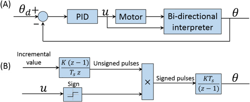
The bi-directional control architecture is illustrated in Fig. 4. Note that this control implementation relies on the high friction and damping within the pneumatic motor when coupled with a 20:1 (or higher) gear reduction. This friction introduces around 0.14 MPa deadband and causes the turbine to halt quickly once the supply pressure is removed. Therefore, a relationship between the motor rotation direction and the air supply channel of the proportional valve (either from port 1 to port 2 or from port 1 to port 4) can be established. Unlike quadrature encoding, binary encoding only provides incremental count value irrespective of the motor rotation direction. However, the direction of rotation can be derived from the control signal using a sign block (compared to 5V offset where the valve spool is in the middle position). The unsigned encoder pulses, obtained from the discrete derivative of the incremental counter value (Fig. 4B), are then multiplied by the control signal sign (i.e., larger than 5 indicates clockwise and smaller than 5 indicates counterclockwise or vice versa). Finally, the integration of the signed pulses generates the motor rotation angle with direction information. This value is scaled to match the rotation angle (in radians) of the geared down output shaft.
Fig.4.
(A) System control block diagram; (B) Detailed expression of the bidirectional interpreter block shows the signal flow chart for obtaining angle values.
III. Results and Discussions
In this section, we describe the experimental evaluation of the motor prototype in terms of torque, speed, and power, as well as MR-conditionality. The closed-loop control performance and comparative study between our motor prototype and state-of-art MR-conditional actuations are also presented
A. Torque, Speed, and Power Characterization
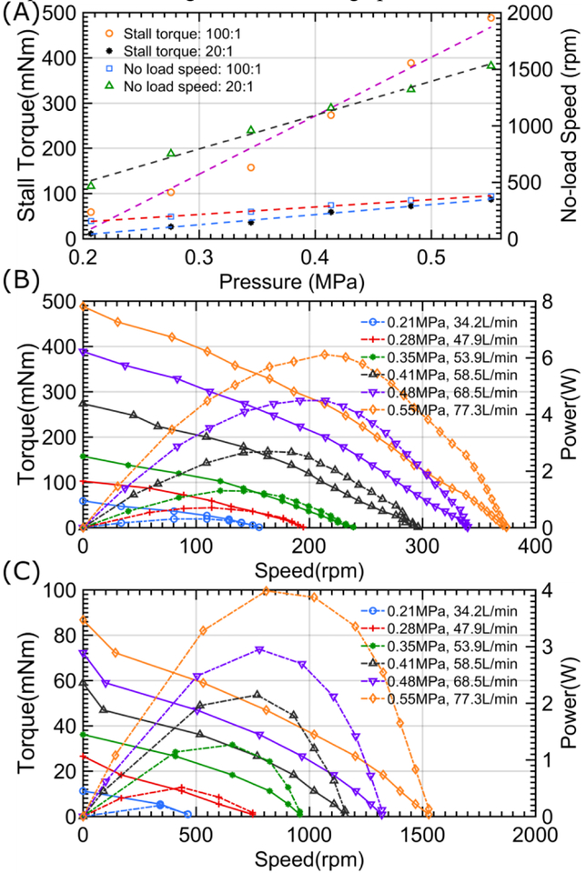
The pneumatic motor was attached to a magnetic particle brake (MPB) (Placid B2) to precisely control resistive torques and simulate loads. The input air pressure to the motor was varied from 0.21 MPa to 0.55 MPa in 0.069 MPa increments [24]. The motor was connected to the air source through a 1 meter air hose. In each experiment with a specific input air pressure, the load applied to the motor output shaft was increased from zero to the stall torque of the motor coupled with 20:1 gearbox and 100:1 gearbox. Each experiment was repeated three times with randomly selected motor rotation directions. Fig. 5A shows the mean value of the resulting stall torque and no-load speed with respect to input air pressure for two different gear ratio combinations. The maximum torque is 460 mNm for 100:1 gearbox, which is comparable to state-of-art MR-conditional piezo actuators (Shinsei USR-30 piezo motor: maximum torque is 100 mNm) and pneumatic step motors. As expected, Fig. 5A (left y-axis) also shows that the torque is approximately proportional to the input air pressure. The slope of the linear fit for 100:1 gear reduction is 5.8 times than that of 20:1 gear reduction, which is similar to the ratio of gear reductions. The gear reduction can be further increased for obtaining higher torques and only limited by the shaft mechanical strength depending on the 3D printing technique. Overload can cause rotor stalling or mechanical failure of the output shaft.
Fig. 5.
(A) The stall torque and no-load speed variation with respect to input pressure of a motor coupled with 100:1 and 20:1 gearboxes; (B-C) Motor with 100:1 gearbox and 20:1 gearbox torque-speed and power-speed curve. The flow rate with respect to different input pressure (listed in the legend of Fig. 5B-C) was calculated by setting the air tank pressure to 0.62MPa and monitoring the pressure drop in a given time.
Similarly, tests were performed to investigate the motor no-load speed variation against input pressure ranging from 0.21 MPa to 0.55 MPa at 0.069 MPa increments. The motor shaft was coupled with a tachometer (ServoTek® SA-740A-2 DC) to measure the speed with the unit of revolutions per minute (RPM). The no-load speed and pressure relationship can be seen in Fig. 5A (right y-axis). The proposed motor runs about ten times faster than the state-of-art MR-conditional stepper motors [20]. Higher input air pressure leads to higher output speed and the maximum output speed is limited by the bearing specifications used in the motor. The motor speed can be well approximated by a linear relationship with respect to input pressure as illustrated in Fig. 5A (right y-axis). It should also be noted that the slope difference of the linear fits is consistent with the two gear ratios.
The torque-power vs. speed diagram against input air pressure for the two gear ratios considered here are shown in Fig. 5B–C. The instantaneous torque and speed were calibrated by connecting the shafts of the aforementioned magnetic brake, tachometer and pneumatic motor in series. The resistive torque applied to the motor shaft was increased from zero to maximum stall torque. The tachometer calibrated the steady state angular velocity at the specific load. Similar to the standard motor characterization method, the power is calculated by multiplying the instantaneous torque by angular speed [30]. The parabolic curves in Fig. 5B–C show the relationship between power and speed. The maximum power of the motor coupled with a 100:1 and 20:1 gearboxes are approximately 6 W and 4 W at 210 rpm and 810 rpm respectively. The output power with the 20:1 gear motor is less than that of 100:1 from the calibrated torque-speed curve. The power calibrated in Figure 5 can be written in the following equation
| (1) |
where Pout is the output power calculated according to the torque-speed curve in Figure 5, Pmotor is the real motor power generated from the air flow kinetic energy, τf is the generalized dissipative torque which includes the gear friction and the torque caused by axial misalignment, ω is the motor output speed. Since the motor coupled with a smaller gearbox has a much larger output speed (approximately 5 times) at the same input pressure, the power (τfω) consumed by the generalized dissipative torque is larger. This explains why the motor output power varies in two different gear ratios. Coupling a 100:1 gearbox to the motor could reduce the efficiency due to the friction of additional planetary gearbox. However, the motors are expected to be powered by the standard medical gas (pressure 0.35Mpa), surgical air supply (pressure 0.7Mpa) or the rotatory pump used in [16] with the maximum pressure of 0.83Mpa, and hence the efficiency requirements were ignored in the design process.
B. Motor Control Performance
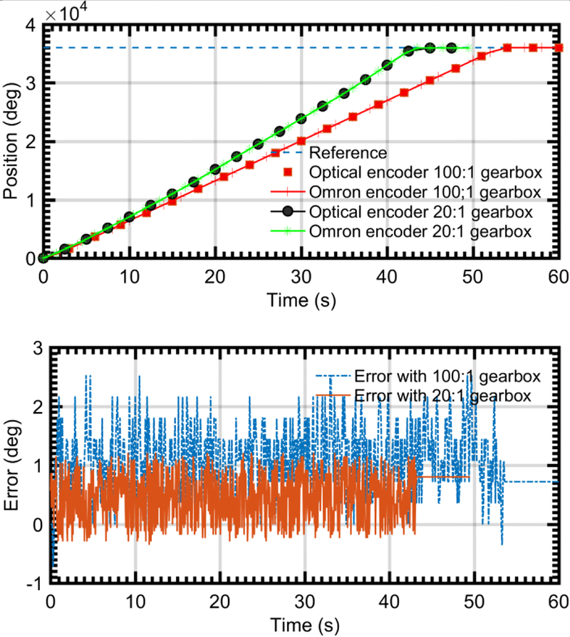
In this section, we investigate the closed-loop performance of the proposed pneumatic motor employing the bi-directional control method discussed in Section II-C. The proposed optical encoding accuracy was evaluated by a commercial encoder (Omron part no. E6C2-CWZ6C, 1000 P/R). A step input of 200π rad (output shaft rotation angle) was sent to the motor controller and both encoders’ signal matched well (Fig. 6). Error is defined as the binary encoder signal minus the Omron encoder signal. The binary encoder signal leads the Omron encoder signal as it detects the rotor rotation while the Omron encoder detects the output shaft rotation. The mean error of the motor coupled to a 20:1 gearbox is less than the motor coupled to 100:1 gearbox (0.5° vs 1°), which is caused by the smaller backlash with fewer gearbox modules. The final state error performance between these two scenarios shows opposite (0.7° with 100:1 gearbox vs 0.8° with 20:1 gearbox) since 100:1 gearbox has higher encoding resolution. In both scenarios, the motor achieves sub-degree error, which validates the accuracy of the proposed optical encoding methods.
Fig. 6.
Encoder accuracy evaluation. The difference (bottom image) between these two encoder signals is also shown.
In the motor control experiment, the motor was provided set-point, square and sinusoid reference tracking signals. The bidirectional control algorithm was implemented in a Simulink Realtime target machine as discussed in Section II-C. Input air pressure to the proportional 5/3 valve was set to 0.41 MPa, which is available in most hospitals. The control experiments were performed in two stages described below. Simulating a typical application scenario, where the pneumatic valves are placed in the control room, an 8m was used to provide air supply to the motor. The use of 8m air hose adds additional dynamic effects which prevents the true characterization of the proposed pneumatic motor. Hence, the tests are repeated using a shorter air hose of 0.2m in length. 8m air hose leads to the motor response delay when the control command changes.
Motor set-point positioning performance is evaluated under different experimental scenarios, namely a motor coupled with a different gearbox, air hose lengths, motor loads and target rotation angles. Similar to the testing protocol in [19], three different target positions (120°, 240° and 360°) are selected in the experimental study. Motor accuracy performance is evaluated by the mean and standard deviation (Std) of the error, where the error is defined by the difference between the target angle and final angle read from the optical encoder. The motor repeatability performance is evaluated by the Coefficient of Variation (CV) [31, 32], which is expressed as a percentage. A smaller CV value indicates a better repeatability in the control performance. Each data in Table 2 was calculated from 8 tests at the identical experimental conditions. The motor coupled to a 20:1 gearbox with long air hose cannot provide constant output power due to the significant air flow loss. Therefore, the motor coupled with a 400:1 gearbox was included in the experimental study. A higher gear ratio is also preferred in practical applications of the proposed motor [33]. The motor accuracy performance is comparable to the pneumatic stepper motor counterparts (e.g., Masamune et al motor has an approximate error of 1.9° at the 360° target position [19], Chen et al motor has an error of 2° at the 360° target position [24]). The set-point positioning accuracy is improved when the motor coupled to a large gearbox due to the increased encoding resolution. Similarly, the motor repeatability performance is improved with high gear ratios as the motor is halted relatively faster with the increased gearbox friction.
Table 2.
Motor control accuracy and repeatability test
| Motor coupled with 20:1 gearbox | ||||||||||
| Hose length(m) | Load (mN.m) | 120° | 240° | 360° | ||||||
| Mean error | Std | CV | Mean error | Std | CV | Mean error | Std | CV | ||
| 0.2 | 0 | 1.99° | 0.87° | 0.71% | 1.00° | 0.89° | 0.37% | 1.06° | 0.95° | 0.26% |
| 20 | 3.37° | 1.06° | 0.86% | 3.70° | 1.30° | 0.53% | 0.00° | 0.00° | 0.00% | |
| 8 | 0 | 2.00° | 1.64° | 1.34% | 1.76° | 1.64° | 0.68% | 0.90° | 0.38° | 0.11% |
| N/A | N/A | N/A | N/A | N/A | N/A | N/A | N/A | N/A | N/A | |
| Motor coupled with 100:1 gearbox | ||||||||||
| Hose length(m) | Load (mN.m) | 120° | 240° | 360° | ||||||
| Mean error | Std | CV | Mean error | Std | CV | Mean error | Std | CV | ||
| 0.2 | 0 | 1.50° | 0.96° | 0.79% | 1.44° | 0.70° | 0.29% | 1.50° | 1.31° | 0.36% |
| 100 | 1.35° | 0.69° | 0.57% | 1.35° | 0.89° | 0.37% | 1.50° | 1.70° | 0.47% | |
| 8 | 0 | 1.54° | 1.34° | 1.10% | 1.35° | 0.70° | 0.29% | 1.78° | 1.48° | 0.41% |
| 50 | 0.97° | 0.64° | 0.53% | 1.50° | 0.90° | 0.37% | 1.10° | 0.93° | 0.26% | |
| Motor coupled with 400:1 gearbox | ||||||||||
| Hose length(m) | Load (mN.m) | 120° | 240° | 360° | ||||||
| Mean error | Std | CV | Mean error | Std | CV | Mean error | Std | CV | ||
| 0.2 | 0 | 1.36° | 0.47° | 0.39% | 0.15° | 0.00° | 0.00% | 0.73° | 0.60° | 0.17% |
| 100 | 0.56° | 0.50° | 0.41% | 1.16° | 0.45° | 0.19% | 1.20° | 0.75° | 0.21% | |
| 8 | 0 | 1.05° | 0.50° | 0.41% | 0.70° | 0.66° | 0.27% | 0.47° | 0.39° | 0.11% |
| 50 | 0.20° | 0.07° | 0.06% | 0.28° | 0.05° | 0.02% | 0.45° | 0.24° | 0.07% | |
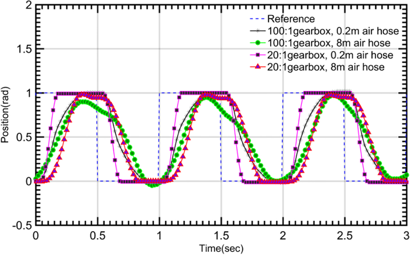
Square wave response shows that the motor with either gearbox can track a 1 Hz square wave reference signal well and error accumulation was not observed. Compared to the step signal tracking with 0.2 m air hose, the 8 m air hose adds additional delay (0.4 s) in the step response. Rising time is slightly increased for both gear reductions (0.8 s vs 0.4 s for 100:1 gearbox; 0.25 s vs 0.1 s for 20:1 gearbox). However, no significant steady state error variation was observed in both cases. The motor with 8 m air hose is hard to track the 1 Hz square signal when it is coupled with the 100:1 gearbox. In all the experimental characterization results, motor output position will be out of phase and start to oscillate when the input frequency is higher [34].
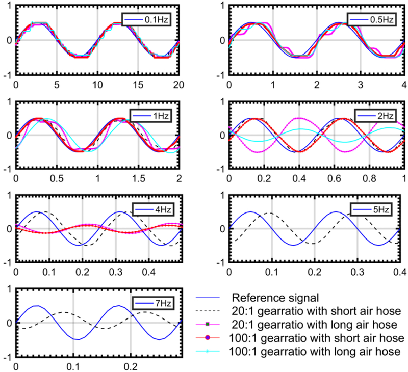
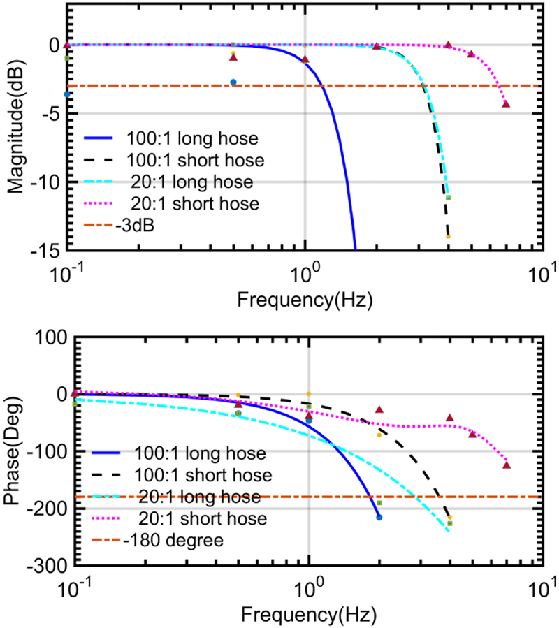
The air motor bandwidth was calibrated with no load. A unit sinusoidal position command signal with a variety of frequencies was sent to the motor controller. The magnitude of the measured motor position movement was recorded to assess the motor bandwidth. Fig. 8 show the response of the proposed motor with 100:1 and 20:1 gearbox setups respectively. In low-frequency range, the motor with either gearhead could track the reference signal. However, significant phase lag was observed in both cases when the reference signal frequency was increased. The bandwidth and phase shift of the motor with a 20:1 gearbox were slightly better compared to the 100:1 gearbox. This is due to the reduced friction and inertia with smaller gear ratio. In addition, the motor coupled with a larger gearbox has slower output shaft rotation speed, which makes it slower to respond the command signal. 8m air hose reduces the system bandwidth from 3.1 Hz to 1.1 Hz with the 100:1 gearbox and from 6.5 Hz to 3.5 Hz with the 20:1 gearbox. Results in Fig. 9 show that the motor supplied with 8m air hose has −3 dB bandwidth of approximately 1.1 Hz (phase lag: 1 rad or 57 degrees), which is higher than human tracking bandwidth (1 Hz) [35].
Fig. 8.
The unit amplitude (1rad) sinusoidal signal tracking performance of the motor with different gearboxes and air hose length.
Fig. 9.
Motor bandwidth corresponding to different gearboxes and air hose length
C. MR-conditionality Evaluation
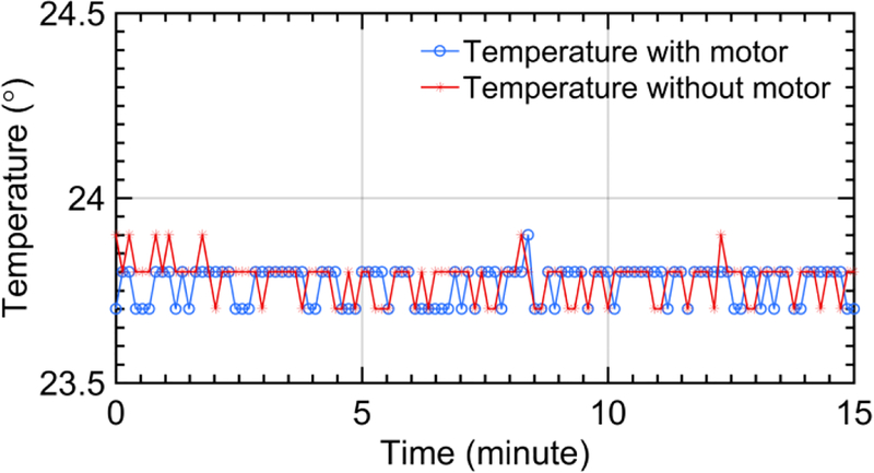
MRI test according to the ASTM F2182 was performed to measure the radio frequency induced temperature variance of the proposed motor during the MRI scanning [36]. The experiment was performed in a 3T Philips MR scanner. The temperature of the motor was measured by using the fiber-optic thermal probe (Luxtron 812, LumaSense Technologies Inc., Santa Clara, CA, USA) in a 15 minutes scanning. The test was performed in two steps. Firstly, temperature rise close to the brass threaded rod was measured by the probe throughout the scanning. The reason to measure the temperature near the brass rod is that it creates the greatest heat if any. Secondly, the motor was removed and the temperature rise at the same position with respect to MRI scanner was measured. The time series temperature data of the probe with/without motor is shown as follows. Mean and standard deviation of these time series temperature data are 23.78°C ± 0.05°C and 23.76°C ± 0.05°C respectively. No significant heating was observed throughout the test.
MRI test according to the ASTM F2119 was performed to evaluate the MR image artifact produced by the motor [37]. The motor was immersed in a CuSO4 bath and immobilized with respect to the bath through a waterproof tape (red arrows in Fig. 11). The recommended MR scanning parameters based on the F2119 protocol were used to obtain the images. Image artifact was defined when the pixel intensity changed over 30% due to the presence of the motor. Maximum artifact width is 79.5 mm in the axial direction (left of Fig. 11) and 45 mm in the radial direction (right of Fig. 11), while the real physical dimensions in the axial direction and radial direction are 79 mm and 44 mm respectively.
Fig. 11.
Image artifact of motor with a 100: 1 gearbox in the axial and radial directions
MR test according to the F2052 and F2213 standards were also performed [38, 39]. No magnetically induced forces and torques were observed in the experiment. The motor is classified as the MR-conditional according to the ASTM F2503 standard since it has only been validated in a 3T MRI scanner and presented no hazard in this MR environment [7].
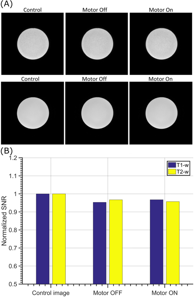
The motor MR-conditionality is also evaluated by 1) region of interest (ROI) image artifact created by the motor and 2) image signal to noise ratio (SNR) variation at the ROI [19, 24]. The MR image of a phantom bottle filled with the CuSO4 solution was obtained under three different conditions: no motor in the scanner, the un-actuated motor in the scanner, and actuated motor in the scanner. In the latter two MR compliance tests, the motor was placed in contact with the phantom bottle outer surface and securely fixed with surgical tape throughout the test at the isocenter of the scanner. Two different imaging sequences, T1-weighted (T1-W) and T2- weighted (T2-W), were applied to analyze the motor MR- conditionality performance. The scanning parameters are listed in Table 3. The MR images of the phantom bottle for the above conditions are shown in Fig. 12A, which indicates that no image artifact was created by the introduction of the motor in both imaging sequences.
Table 3.
Scanning parameters for MR-compatibility evaluation
| Sequence | TE (ms) | TR(ms) | FA(°) | Resolution (mm^3) |
|---|---|---|---|---|
| Tl | 4.6 | 10 | 15 | 0.5×0.5×1.3 |
| T2 | 100 | 5032 | 90 | 0.3×0.3×5.5 |
Fig. 12.
(A) T1-w (1st row) and T2-w (2nd row) MR phantom images obtained with 3T Philips MR scanner. It can be seen that no image artifacts or distortion were observed; (B) SNR of phantom MR image under three different scenarios. The motor setup caused less than 5% SNR reduction.
The SNR of the MR image was calculated by the following equation,
| (2) |
where μ1is the mean of the 40×40 pixel region at the center of the image, and σ2 is the standard deviation of the 40×40 pixel region at the corner of image [40]. Fig. 10B shows the SNR corresponding to the aforementioned three scenarios under T1-w and T2-w imaging sequences. The maximum SNR variation was <5% in all cases, which is significantly better than the state-of-art MR-conditional piezoelectric motors [8, 9] and pneumatic actuators [19].
Fig.10.
Time series temperature data
D. Comparative Study
The comparative study between the proposed motor and the existing counterparts includes the design complexity, fabrication cost, dynamic performance, encoding method, and MR-compliance (Table 4). It should be noted that some MR-conditional pneumatic actuators such as [18, 23, 41] were not listed in the study due to the lack of technical data. In addition, a commercially available MR-conditional piezo motor was included in the study for highlighting the advantages of the proposed motor.
Table 4.
Motor comparative study
| Stoianovici [16] |
Sajima [19] |
Chen [24] |
Chen [20] |
Piezomotor [42] |
Proposed motor3 |
|
|---|---|---|---|---|---|---|
| Size (mm) | ∅85 × 30 | ∅30 × 35 | 95 × 60 × 37 | ∅10 × 60 | ∅35 × 31.5 | ∅44 × 794 |
| #of Components | ~25 | ~10 | 6 | 7 | N/A | 5 |
| Resolution (des)1 | 3.33 | 4.19 | 3.6 | 60 | 0.72 | 1.8 |
| Speed (rpm) | 166.6 | 50 | 2.4 | 90 | 300 | 370 |
| Torque (mNm)2 | 640 | 150 | 800 | 2.4 | 100 | 460 |
| Power (W) | 35 | 0.47 | 0.126 | 0.0113 | 2.5 | 6 |
| Encoding | Yes | No | No | No | Yes | Yes |
| MR-safe/conditio nal | MR-safe | MR-safe | MR-conditional | MR-conditional | MR-conditional | MR-conditional |
Resolution indicates the step size of the state-of-art step motors or resolution of the piezo motor encoder;
Torque is the reported maximum shaft output value with gearbox if any;
The proposed motor is coupled with a 100:1 gearbox;
The motor total length varies with respect to the number of gearbox modules;
This is calculated from torque-speed data under normal operation range. The motor power is the function of air hose length, input pressure and speed. Maximum power was measured up to 37W.
As can be seen in Table 4, the proposed motor consists of the fewest number of components. For instance, unlike the Shinsei piezo motor which costs over $500, the main components of the motor can be fabricated using low-cost 3D printing techniques combined with the off the shelf components. Noting the high rotation speed of the proposed motor, the user has high flexibility to choose gear ratio and input air pressure combinations to meet a range of practical torque-speed requirements. Further, the proposed motor has relatively high output power compared to existing MR-conditional actuators. Moreover, the use of MR-conditional all-optical encoding technique, without electrical wiring, eliminates image artifacts and maintains minimal SNR variation.
IV. Conclusions
This paper presented the design, characterization, and control of a low-cost MR-conditional pneumatic motor. The motor was fabricated using standard additive manufacturing techniques. It was designed to use commercially available modular plastic gearboxes, thus providing high design flexibility. The prototype pneumatic motor produced 460 mNm stall torque and 370 rpm no-load speed with 100:1 gear reduction. However, the external load should be smaller than the motor stall torque so as not to backdrive the motor in the practical applications. Despite the low-cost, the proposed motor yielded comparable power output and dynamic performance to state-of-art MR-conditional actuators. A custom designed MR-conditional optical encoder was also presented. The encoder was integrated into the motor housing, resulting in a compact design. Closed-loop control experiments showed that the motor using a 100:1 gear reduction and 8 m air hose has a −3 dB bandwidth of 1.1 Hz. A 3T MRI conditionality study showed that no observable image artifacts were created by the pneumatic motor. MR image SNR was reduced less than 5% in both T1 and T2 weighted imaging sequences, thus making the proposed motor ideal for MR-conditional robotic applications.
Fig. 7.
Square reference signal tracking with 100:1 gearbox and 20:1 gearbox in terms of different air hose length.
Acknowledgments
This work was funded by the National Institute of Health under the grant 1R21NS091735–01. The authors gratefully acknowledge the free samples provided by igus® Inc, USA.
Biographies
Yue Chen

received the B.S. degree in Vehicle Engineering from Hunan University, and the M.Phil degree in Mechanical Engineering from Hong Kong Polytechnic University. He was a graduate student at the University of Georgia from 2013 to 2015. He is PhD student in the department of Mechanical Engineering at Vanderbilt University. His research interests include medical robotics and soft robots.
Isuru S. Godage

(M’03) is an Assistant Professor in the School of Computing at DePaul University, Chicago. He received his B.Sc. Eng (Hons) degree in Electronic and Telecommunications Engineering from University of Moratuwa, Sri Lanka (2007) and Ph.D. in Robotics, Cognition, and Interaction Technologies from University of Genoa - Italian Institute of Technology, Italy (2013). His research interests include design, modeling, and experimentation of novel hyper-dimensional soft and continuum robotic systems in manipulation and locomotion toward disaster relief, search and rescue, and healthcare applications. He is the PI of an ongoing NSF funded research to study soft modular robots using stiff and compliant materials.
Zion Tsz Ho Tse

received his Ph.D. in Mechatronics in Medicine from Imperial College London. Currently he is an associate professor in the School of Electrical & Computer Engineering and the Principal Investigator of the Medical Robotics Lab at the University of Georgia, Athens, GA, USA. Before joining UGA, he was a research fellow at Harvard Medical School and Brigham and Women’s Hospital. Dr. Tse has been involved in designing and prototyping a broad range of novel analog-digital electronic devices, most of which have been applied in numerous clinical and industrial environments.
Robert J. Webster III

(S’97–M’08–SM’14) received the B.S. degree in electrical engineering from Clemson University, Clemson, SC, USA, in 2002, and the M.S. and Ph.D. degrees in mechanical engineering from The Johns Hopkins University, Baltimore, MD, USA, in 2004 and 2007, respectively. In 2008, he joined the Faculty of Vanderbilt University. He is currently an Associate Professor of Mechanical Engineering, Electrical Engineering, Otolaryngology, Neurological Surgery, and Urologic Surgery, and directs the Medical Engineering and Discovery Laboratory at Vanderbilt. He serves on the steering committee for the Vanderbilt Institute in Surgery and Engineering, which brings together physicians and engineers to solve challenging clinical problems. He is the Chair of the SPIE Image-Guided Procedures, Robotic Interventions, and Modeling Conference. He is a founder and serves as president of Virtuoso Surgical, Inc. His research interests include surgical robotics, image-guided surgery, and continuum robotics. Dr. Webster has received the IEEE Robotics & Automation Society Early Career Award, the National Science Foundation CAREER award, the Robotics Science and Systems Early Career Spotlight Award, and the IEEE Volz Award, and the Vanderbilt Engineering Award for Excellence in Teaching.
Eric J. Barth

received the B. S. degree in engineering physics from the University of California at Berkeley, and the M. S. and Ph. D. degrees from the Georgia Institute of Technology in mechanical engineering in 1994, 1996, and 2000 respectively.
He is currently an associate professor of mechanical engineering at Vanderbilt University, Nashville, TN. His research interests include the design, modeling and control of mechatronic and fluid power systems, free-piston internal combustion and free-piston Stirling engines, energy storage and energy harvesting, MRI compatible pneumatic robots, and applied non-linear control.
Contributor Information
Yue Chen, Department of Mechanical Engineering, Vanderbilt University, Nashville, TN, 37212, USA..
Isuru S. Godage, Department of Mechanical Engineering, Vanderbilt University, Nashville, TN, 37212, USA..
Zion Tsz Ho Tse, College of Engineering, The University of Georgia, Athens, GA, 30605, USA..
Robert J. Webster, III, Department of Mechanical Engineering, Vanderbilt University, Nashville, TN, 37212, USA..
Eric J. Barth, Department of Mechanical Engineering, Vanderbilt University, Nashville, TN, 37212, USA..
V. Reference
- [1].Gassert R, Burdet E, and Chinzei K, “Opportunities and challenges in MR-compatible robotics,” IEEE Engineering in medicine and biology magazine, vol. 27, pp. 15–22, 2008. [DOI] [PubMed] [Google Scholar]
- [2].McRobbie DW, Moore EA, Graves MJ, and Prince MR, MRI from Picture to Proton: Cambridge University Press, 2006. [Google Scholar]
- [3].Fischer GS, DiMaio SP, Iordachita II, and Fichtinger G, “Robotic assistant for transperineal prostate interventions in 3T closed MRI,” in Medical Image Computing and Computer-Assisted Intervention–MICCAI 2007, ed: Springer, 2007, pp. 425–433. [DOI] [PubMed] [Google Scholar]
- [4].Yang B, Tan U-X, McMillan AB, Gullapalli R, and Desai JP, “Design and control of a 1-DOF MRI-compatible pneumatically actuated robot with long transmission lines,” Mechatronics, IEEE/ASME Transactions on, vol. 16, pp. 1040–1048, 2011. [DOI] [PMC free article] [PubMed] [Google Scholar]
- [5].Masamune K, Kobayashi E, Masutani Y, Suzuki M, Dohi T, Iseki H, and Takakura K, “Development of an MRI-compatible needle insertion manipulator for stereotactic neurosurgery,” Computer Aided Surgery, vol. 1, pp. 242–248, 1995. [DOI] [PubMed] [Google Scholar]
- [6].Kwok KW, Chen Y, Chau TCP, Luk W, Nilsson K, Schmidt EJ, and Tse Z, “MRI-based visual and haptic catheter feedback: simulating a novel system’s contribution to efficient and safe MRI-guided cardiac electrophysiology procedures,” Journal of Cardiovascular Magnetic Resonance, vol. 16, p. 50, 2014.25191878 [Google Scholar]
- [7].A. F2503. (August 2005). Standard Practice for Marking Medical Devices and Other Items for Safety in the Magnetic Resonance Environment. Available: www.astm.org [DOI] [PubMed]
- [8].Krieger A, Song S-E, Cho NB, Iordachita II, Guion P, Fichtinger G, and Whitcomb LL, “Development and evaluation of an actuated MRI-compatible robotic system for MRI-guided prostate intervention,” Mechatronics, IEEE/ASME Transactions on, vol. 18, pp. 273–284, 2013. [DOI] [PMC free article] [PubMed] [Google Scholar]
- [9].Elhawary H, Zivanovic A, Rea M, Davies B, Besant C, McRobbie D, de Souza N, Young I, and Lampérth M, “The feasibility of MR-image guided prostate biopsy using piezoceramic motors inside or near to the magnet isocentre,” in International Conference on Medical Image Computing and Computer-Assisted Intervention, 2006, pp. 519–526. [DOI] [PubMed] [Google Scholar]
- [10].Krieger A, Iordachita I, Song S-E, Cho NB, Guion P, Fichtinger G, and Whitcomb LL, “Development and preliminary evaluation of an actuated MRI-compatible robotic device for MRI-guided prostate intervention,” in Robotics and Automation (ICRA), 2010 IEEE International Conference on, 2010, pp. 1066–1073. [Google Scholar]
- [11].Wendt O, Oellinger J, Luth T, Felix R, and Boenick U, “The Effects of the Use of Piezoelectric Motors in a 1.5-Tesla High-Field Magnetic Resonance Imaging System (MRI)-Effekte von piezoelektrischen Motoren in einem 1, 5-Tesla-Hochfeld-Magnetresonanztomographen (MRT),” Biomedizinische Technik/Biomedical Engineering, vol. 45, pp. 20–25, 2000. [DOI] [PubMed] [Google Scholar]
- [12].Fischer GS, Cole G, and Su H, “Approaches to creating and controlling motion in MRI,” in 2011 Annual International Conference of the IEEE Engineering in Medicine and Biology Society, 2011, pp. 6687–6690. [DOI] [PubMed] [Google Scholar]
- [13].Gassert R, Yamamoto A, Chapuis D, Dovat L, Bleuler H, and Burdet E, “Actuation methods for applications in MR environments,” Concepts in Magnetic Resonance Part B: Magnetic Resonance Engineering, vol. 29, pp. 191–209, 2006. [Google Scholar]
- [14].Stoianovici D, Kim C, Srimathveeravalli G, Sebrecht P, Petrisor D, Coleman J, Solomon SB, and Hricak H, “MRI-safe robot for endorectal prostate biopsy,” IEEE/ASME Transactions on Mechatronics, vol. 19, pp. 1289–1299, 2014. [DOI] [PMC free article] [PubMed] [Google Scholar]
- [15].Fischer GS, Iordachita I, Csoma C, Tokuda J, DiMaio SP, Tempany CM, Hata N, and Fichtinger G, “MRI-compatible pneumatic robot for transperineal prostate needle placement,” IEEE/ASME transactions on mechatronics, vol. 13, pp. 295–305, 2008. [DOI] [PMC free article] [PubMed] [Google Scholar]
- [16].Stoianovici D, Patriciu A, Petrisor D, Mazilu D, and Kavoussi L, “A new type of motor: Pneumatic step motor,” Mechatronics, IEEE/ASME Transactions on, vol. 12, pp. 98–106, February 2007. [DOI] [PMC free article] [PubMed] [Google Scholar]
- [17].Fischer GS, Enabling technologies for MRI guided interventional procedures: ProQuest, 2009. [Google Scholar]
- [18].Bosboom DGH, Fütterer JJ, and Bosboom J, “Motor system, motor, and robot arm device comprising the same,” ed: Google Patents, 2010. [Google Scholar]
- [19].Sajima H, Kamiuchi H, Kuwana K, Dohi T, and Masamune K, “MR-Safe Pneumatic Rotation Stepping Actuator,” Journal ref: Journal of Robotics and Mechatronics, vol. 24, pp. 820–827, 2012. [Google Scholar]
- [20].Chen Y, Mershon CD, and Tse ZTH, “A 10-mm MR-Conditional Unidirectional Pneumatic Stepper Motor,” Mechatronics, IEEE/ASME Transactions on, vol. PP, pp. 1–7, 2014. [DOI] [PMC free article] [PubMed] [Google Scholar]
- [21].Groenhuis V and Stramigioli S, “Laser-Cutting Pneumatics,” IEEE/ASME Transactions on Mechatronics, vol. 21, pp. 1604–1611, 2016. [Google Scholar]
- [22].GUO Z, LUN T, Chen Y, Hao S, Chan D, and Kwok K, “Novel Design of an MR-safe Pneumatic Stepper Motor for MRI-guided Robotic Interventions,” in Hamlyn Symposium on Medical Robotics, 2016. [Google Scholar]
- [23].Secoli R, Robinson M, Brugnoli M, and y Baena FR, “A low-cost, high-field-strength magnetic resonance imaging–compatible actuator,” Proceedings of the Institution of Mechanical Engineers, Part H: Journal of Engineering in Medicine, vol. 229, pp. 215–224, 2015. [DOI] [PubMed] [Google Scholar]
- [24].Chen Y, Kwok K-W, and Tse ZTH, “An MR-Conditional High-Torque Pneumatic Stepper Motor for MRI-Guided and Robot-Assisted Intervention,” Annals of biomedical engineering, vol. 42, pp. 1823–1833, 2014. [DOI] [PMC free article] [PubMed] [Google Scholar]
- [25].Comber DB, Slightam JE, Gervasi VR, Neimat JS, and Barth EJ, “Design, additive manufacture, and control of a pneumatic mr-compatible needle driver,” IEEE Transactions on Robotics, vol. 32, pp. 138–149, 2016. [DOI] [PMC free article] [PubMed] [Google Scholar]
- [26].Chen Y, Squires A, Seifabadi R, Xu S, Agarwal H, Bernardo M, Pinto P, Choyke P, Wood B, and Zion T, “Robotic System for MRI-guided Focal Laser Ablation in the Prostate,” IEEE/ASME Transactions on Mechatronics. [DOI] [PMC free article] [PubMed] [Google Scholar]
- [27].Erlach J, “Pelton turbine,” ed: Google Patents, 1990. [Google Scholar]
- [28].Chen Y, Wang W, Schmidt EJ, Kwok K-W, Viswanathan AN, Cormack R, and Tse ZTH, “Design and Fabrication of MR-Tracked Metallic Stylet for Gynecologic Brachytherapy,” IEEE/ASME Transactions on Mechatronics, vol. 21, pp. 956–962, 2016. [DOI] [PMC free article] [PubMed] [Google Scholar]
- [29].Olaby O, Brun X, Sesmat S, Redarce T, and Bideaux E, “CHARACTERIZATION AND MODELING OF A PROPORTIONAL VALUE FOR CONTROL SYNTHESIS,” in Proceedings of the JFPS International Symposium on Fluid Power, 2005, pp. 771–776. [Google Scholar]
- [30].Jain K and Chitale A, Textbook of Production Engineering: PHI Learning Pvt. Ltd., 2014. [Google Scholar]
- [31].Centore P, “The coefficient of variation as a measure of spectrophotometric repeatability,” Color Research & Application, vol. 41, pp. 571–579, 2016. [Google Scholar]
- [32].Carstensen B, “Repeatability, reproducibility and coefficient of variation,” Comparing Clinical Measurement Methods: A Practical Guide, pp. 107–114, 2010. [Google Scholar]
- [33].Chen Y, Godage IS, Sengupta S, Liu CL, Weaver KD, Barth EJ, and Webster III RJ, “An MRI-Compatible Robot for Intracerebral Hemorrhage Removal,” Journal of Medical Devices, Accepted, 2016. [Google Scholar]
- [34].Aström KJ and Murray RM, Feedback systems: an introduction for scientists and engineers: Princeton university press, 2010. [Google Scholar]
- [35].Falk V, “Manual control and tracking—a human factor analysis relevant for beating heart surgery,” The Annals of thoracic surgery, vol. 74, pp. 624–628, 2002. [DOI] [PubMed] [Google Scholar]
- [36].A. F2182. (April 2011). Test Method for Measurement of Radio Frequency Induced Heating Near Passive Implants During Magnetic Resonance Imaging. Available: www.astm.org
- [37].A. F2119. (March 2013). Test Method for Evaluation of MR Image Artifacts from Passive Implants. Available: www.astm.org
- [38].A. F2052. (September 2015). Test Method for Measurement of Magnetically Induced Displacement Force on Medical Devices in the Magnetic Resonance Environment. Available: www.astm.org
- [39].A. F2213. (October 2010). Test Method for Measurement of Magnetically Induced Torque on Medical Devices in the Magnetic Resonance Environment. Available: www.astm.org [DOI] [PMC free article] [PubMed]
- [40].Chinzei K, Kikinis R, and Jolesz FA, “MR compatibility of mechatronic devices: Design criteria,” Medical Image Computing and Computer-Assisted Intervention, Miccai’99, Proceedings, vol. 1679, pp. 1020–1030, January 1999. [Google Scholar]
- [41].Comber DB, Slightam JE, Barth EJ, Gervasi VR, and Webster RJ, “Design and Precision Control of an MR-Compatible Flexible Fluidic Actuator,” in ASME/BATH 2013 Symposium on Fluid Power and Motion Control, 2013, pp. V001T01A048–V001T01A048. [Google Scholar]
- [42].Corporation S. (2016). Shinsei Motor Datasheet. Available: http://www.shinsei-motor.com/English/product/index.html [Google Scholar]


