Abstract.
Shoulder arthrography is a diagnostic procedure which involves injecting a contrast agent into the joint space for enhanced visualization of anatomical structures. Typically, a contrast agent is injected under fluoroscopy or computed tomography (CT) guidance, resulting in exposure to ionizing radiation, which should be avoided especially in pediatric patients. The patient then waits for the next available magnetic resonance imaging (MRI) slot for obtaining high-resolution anatomical images for diagnosis, which can result in long procedure times. Performing the contrast agent injection under MRI guidance could overcome both these issues. However, it comes with the challenges of the MRI environment including high magnetic field strength, limited ergonomic patient access, and lack of real-time needle guidance. We present the development of an integrated robotic system to perform shoulder arthrography procedures under intraoperative MRI guidance, eliminating fluoroscopy/CT guidance and patient transportation from the fluoroscopy/CT room to the MRI suite. The average accuracy of the robotic manipulator in benchtop experiments is 0.90 mm and 1.04 deg, whereas the average accuracy of the integrated system in MRI phantom experiments is 1.92 mm and 1.28 deg at the needle tip. Based on the American Society for Testing and Materials (ASTM) tests performed, the system is classified as MR conditional.
Keywords: shoulder arthrography, magnetic resonance imaging, image-guided, robot
1. Introduction
Arthrography is a diagnostic procedure to evaluate joint condition using medical images. The procedure begins with the injection of the contrast agent under fluoroscopy or computed tomography (CT) guidance. Then the patient is transported to the magnetic resonance imaging (MRI) suite where high-resolution diagnostic images are acquired. Current workflow exposes pediatric patients to ionizing radiation during fluoroscopy or CT, while wait times for an available MRI slot and transfer from fluoroscopy/CT operating room to MRI suite increase procedure time and prolong general anesthesia for younger children. If the waiting time between contrast agent injection and MRI is long, the contrast agent could wash out and the quality of diagnostic image could deteriorate. MR images provide excellent soft tissue contrast without any ionizing radiation, and performing the entire procedure under MRI guidance could potentially reduce the procedure time and improve diagnostic outcome. However, injecting the contrast agent under intraoperative MRI guidance comes with the challenges of the MR environment, including narrow MR scanner bore size, limited ergonomic access to the patient, and manual registration of the surgical scene for accurate needle placement in the joint space. Some of these challenges could be overcome by utilizing an MRI-guided robotic system that can perform contrast agent injection under intraoperative MRI guidance followed by high-resolution diagnostic imaging. Performing the procedure in the same MR room could streamline clinical workflow and possibly shorten procedure time.
Owing to its high magnetic field strength, only nonferrous materials and piezoelectric, hydraulic, or pneumatic actuators can be used in MR environment. Over the past decade, MRI-guided robotic systems have been investigated by many researchers for needle-based, percutaneous interventions. Such systems are categorized by their mounting mechanism: table-mounted and body-mounted. Table-mounted devices are typically bigger and heavier and are rigidly attached to the scanner bed, whereas the body-mounted devices are compact, lightweight, and are attached by means of straps or screws (in cases of neurosurgical interventions). Some of the proposed clinical applications of table-mounted robotic systems for percutaneous interventions under MRI guidance include prostate biopsy,1–6 stereotactic neurosurgery,7–10 breast biopsy,11–13 and needle steering.14,15 There are also a few patient-mounted robotic systems for CT-guided percutaneous interventions.16–18 Although these devices could potentially be adopted for shoulder arthrography, CT lacks the needed soft tissue contrast and results in exposure to radiation. Hungr et al. presented a multimodality compatible robotic manipulator for percutaneous needle procedures which can safely work in both CT and MRI.19 Song et al. and Wu et al. developed an MRI coil-mounted needle alignment mechanism for liver interventions20 and a 2 degrees of freedom (DOFs) device for cryoablation,21 respectively; however, there were not any lightweight and compact robotic systems which could be used for pediatric patients.
In this paper we present an integrated, patient-mounted robotic system for MRI-guided shoulder arthrography procedure in pediatric patients that improves on the two generations of MRI-guided robotic manipulators previously developed by our research groups.22–24 The robot is designed to be lightweight and compact without compromising needle placement accuracy. Also, compared to our previous systems,22,23 this system is more rigid, provides repeatable and accurate homing using optical limit switches, offers better cable management for clinical usage, and makes provision for maintaining a sterile field without any mechanical disassembly. To evaluate the accuracy of the robot mechanism, the benchtop experiments using an optical tracking system are performed. To evaluate the integrated system accuracy and clinical usability, MRI phantom experiments are performed adhering to the proposed clinical workflow described in Sec. 2.5. Also, to investigate the MRI compatibility of the robotic system, American Society of Testing and Materials International (ASTM) -F250325 tests are performed, resulting in the device being classified as MR conditional. Although the system could potentially be used for any needle-based percutaneous interventions, the present robot mounting mechanism is optimized for shoulder arthrography procedures.
2. Methods
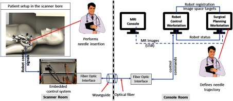
The presented integrated robotic system consists of a four-DOF robotic manipulator, an embedded control system, robot control software, and a surgical planning interface. It provides accurate needle insertion for contrast agent injection inside the MRI bore. Figure 1 shows the layout of the system components and the data flow between them.
Fig. 1.
System block diagram showing all the components, their layout in the operating room, and the data flow between them.
2.1. Electromechanical Design
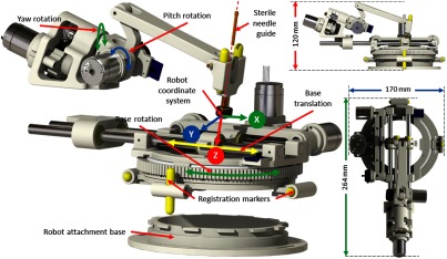
The robotic manipulator provides two DOFs positioning and two DOFs orientation of the needle guide, while needle insertion and rotation are performed manually by the clinician. The kinematic structure of the manipulator is similar to our previous systems;22,23 however, this version of the robotic manipulator is more rigid, accurate, and optimized for clinical usage, with a compact size of and weight of . All the components of the robot have been structurally improved to provide better targeting accuracy. The needle guide is designed such that it could be sterilized and inserted while maintaining the sterile field. As shown in Fig. 2, a sterile brass stylet is the only component that comes in direct contact with the needle as well as the robot (needle guide), creating a barrier between the sterile and nonsterile environments.
Fig. 2.
Robot CAD model showing the DOFs, robot coordinate system, and sterile stylet for needle insertion.
Four joints of the robot can be precisely controlled to align the needle guide to the desired needle insertion trajectory; however, limited space in the MRI scanner bore could result in a collision between the robot and the scanner bore or the patient. To reduce the base rotation of the robot for a given trajectory, the inverse kinematics optimizes the redundancy provided by the base translation and rotation joints. This provides the same workspace as the complete 360 degree base rotation, but with only effective rotation coupled with the base translation. Figure 2 shows robot coordinate system, whereas Table 1 shows motion range and resolution after transmission reductions for each joint.
Table 1.
Motion range of each of the robot joints.
| Joint no. | Joint name | Resolution | Motion range | |
|---|---|---|---|---|
| Min | Max | |||
| 1 | Base rotation (degrees) | 0.022 | −90 | 90 |
| 2 | Base translation (mm) | 0.012 | −40 | 40 |
| 3 | Yaw (deg) | 0.090 | −30 | 30 |
| 4 | Pitch (deg) | 0.180 | −30 | 30 |
The manipulator is manufactured from three-dimensional (3-D) printed nonferrous materials, whereas all the joints are actuated using Piezo LEGS (PiezoMotor, Upsala, Sweden) motors. Optical encoders (E4T, USDigital, Vancouver, Washington) are used for obtaining precise joint positions; quadrature-encoded configuration of these encoders provide 2000 counts per revolution resolution. Custom-designed optical limit switches using opto-interrupter (RPI-221, ROHM Semiconductor, Kyoto, Japan) are used for robot initialization as the encoders provide only the relative position. The homing procedure for the robot is performed by moving each joint to the limit switch and then setting the joint position to a known offset derived by a calibration procedure. A four-axis controller from Galil Motion (Galil Motion Control, Rocklin, California) is configured and coupled with the piezoelectric motor drivers to provide joint space control.
2.2. Robot Control Application
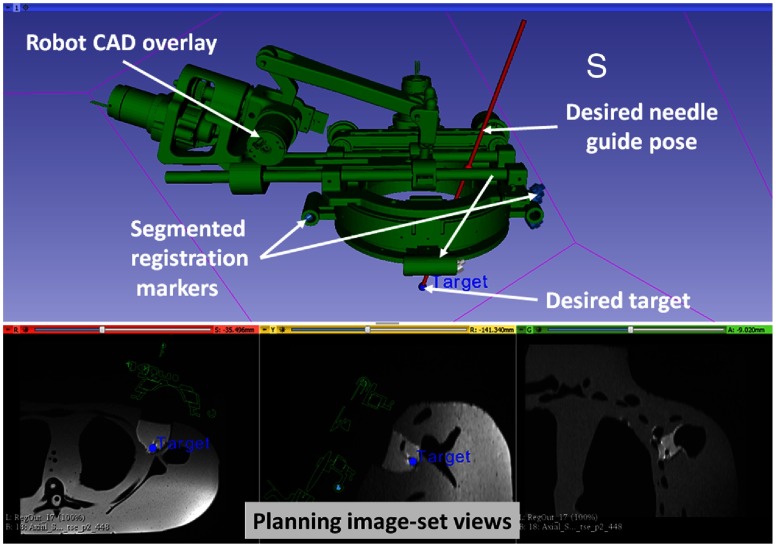
A MATLAB™ (The MathWorks Inc., Natick, Massachusetts)-based graphical user interface application provides both the joint space and the task-space control. The robot control application communicates with the Galil controller to send the desired motion commands in joint space and to request robot status information to display to the user. Since all the joint positions are measured with incremental encoders, the robot control application initializes the robot using embedded optical limit switches installed on each axis. Also, it provides real-time status of the robot and an interface for communication with 3-D Slicer26 for sending registration transformation and current robot pose over OpenIGTLink,27 which is overlaid on intraoperative MR images for the needle trajectory confirmation, as shown in Fig. 3. As shown in Fig. 1, the embedded controller and the robot control application communicate over fiber-optic cable which passes through the waveguide of the MR scanner room.
Fig. 3.
Interface of 3-D Slicer, showing planning and navigation information, and showing four fiducial markers for registering robot to the scanner coordinate system.
2.3. Robot Registration
Registering the transformation between the robot coordinate system and the scanner coordinate system is necessary to define the target trajectory in the image space. As shown in Fig. 2, four MRI visible, cylindrical fiducial markers (MR-SPOT® 121, Beekley Corporation) are attached to the robot base and are segmented using the line marker registration (LMR) module in 3-D Slicer. As shown in Fig. 3, the LMR module segments those four markers as vectors and fits the segmented vectors to predefined geometry from the computer-aided design (CAD) model of the robot base, resulting in six-DOF pose of the robot base in the MRI space. The accuracy of the registration algorithm with a different registration frame was shown to be and .28
2.4. Trajectory Planning
Surgical planning and navigation play important roles in any robot-assisted, image-guided therapy (IGT) procedure, since visualizing the preoperative and intraoperative images and surgical plan allows tracking of the dynamic changes during the procedure. The 3-D Slicer26 is a widely used surgical planning and navigation application for various IGT procedures in research environments. The 3-D Slicer-based surgical planning and navigation workflow is created for preoperative planning and visualization. The 3-D Slicer visualizes robot workspace, overlaid on intraoperative images to convey the reachable workspace of the robot. The surgeon selects the desired target and entry points using three views, as displayed in Fig. 3.
2.5. Clinical Workflow
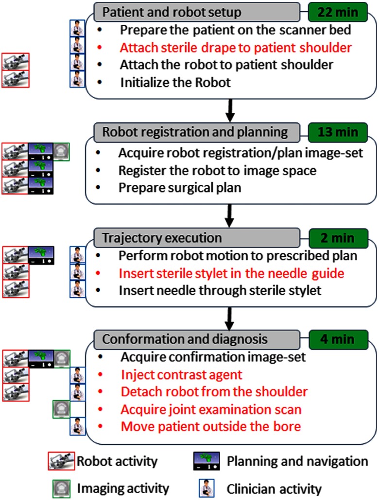
In a typical MRI-guided arthrography procedure, the clinician manually aligns and inserts the needle toward the desired anatomical target using the planning image set. The clinical workflow presented in this paper for robot-assisted, MRI-guided shoulder arthrography procedure is similar to the manual procedure. However, the robot aligns the needle guide to a desired trajectory using the image space target and skin entry points, eliminating the manual guesswork by the clinician. As shown in Fig. 4, the workflow is divided into four phases: (1) patient and robot setup, (2) robot registration and trajectory planning, (3) trajectory execution, and (4) trajectory confirmation and contrast agent injection. The procedure begins with the patient lying on the scanner table with the robot base frame strapped to the shoulder. Then the robot is attached to the base frame and initialized to home position using the embedded limit switches. After the robot is ready, the patient is moved to the isocenter of the scanner to acquire the planning image set. Using the planning image set, the robot is registered to the scanner coordinate system. To reduce the imaging time, the clinician defines the desired target and entry points with the same image set using the 3-D Slicer interface. The robot registration transform and planned target and entry points are transferred to the robot control application over the OpenIGTLink interface. The robot control application performs the inverse kinematics to calculate the desired joint positions to align the robot to the planned insertion trajectory. The clinician observes the robot motion and when the robot has aligned the needle guide to the planned trajectory, he or she inserts the sterile stylet into the needle guide, creating a barrier between the sterile and nonsterile environments. Then the needle is inserted through the sterile stylet and a confirmation scan is performed. If the physician is satisfied with the needle position, he or she injects the contrast agent (this part of the workflow we envision only for the cadaver and clinical trials). After injecting the contrast agent, the robot and the attachment base are detached. At the end, a high-resolution anatomical scan is acquired for diagnosis.
Fig. 4.
Proposed clinical workflow showing various steps for the robot-assisted, MRI-guided shoulder arthrography procedure. Procedure is divided into four phases, on the left of each activity shows what/who are involved for that activity, while, for each phase, measured average time is displayed on the right. Activities shown in red are not considered for the phantom studies; they will be considered for the cadaver and patient trials.
3. Experiments and Results
3.1. Benchtop Accuracy Evaluation
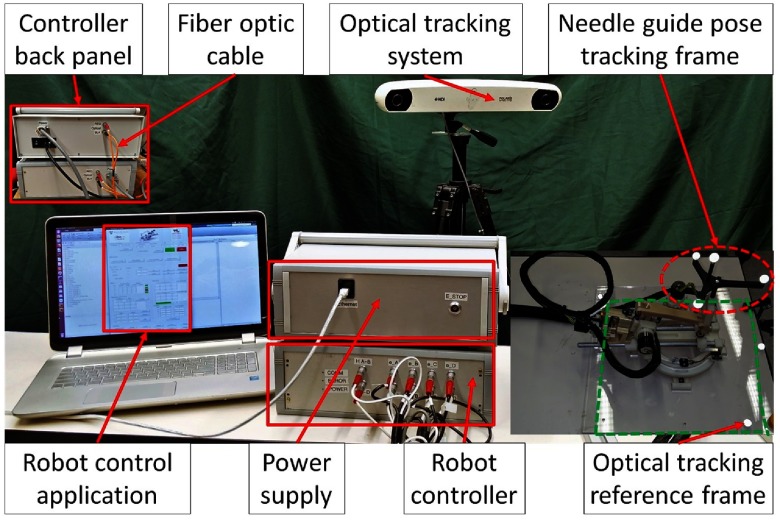
Accuracy and repeatability of the robotic device are evaluated in benchtop setting using an optical tracking system (NDI Polaris Spectra) with an accuracy of 0.25 mm. To define the optical tracking reference frame, we designed a laser cut acrylic plate with four optical markers with an appropriate cutout for mounting the robot in a known position and orientation. A rigid body with a custom 3-D printed attachment is fixed on the needle guide for tracking its position and orientation relative to the reference frame. Figure 5 shows the experiment setup. The position and orientation of the needle guide is tracked relative to the reference rigid body for accuracy and repeatability. Accuracy of the needle tip is evaluated by extrapolating the needle guide pose at 50-mm insertion depth along the needle insertion direction.
Fig. 5.
Benchtop experimental setup showing optical tracking reference frame and robot pose tracking frame.
Accuracy and repeatability are evaluated for the homing procedure (H) and six joint-space targets (T1–T6) spread across the robot workspace. To measure the position error at the needle tip, the desired and measured needle guide poses are extrapolated at the 50-mm insertion depth. To measure the orientation error, the Euler angles between the desired and measured transformation are compared. Experiments are performed in the following sequence: H-T1-…-T6 and were repeated 20 times. Table 2 shows the average position and orientation error at the needle tip for the homing procedure and each of the six targets, with average positioning errors of 0.51, 0.30, and 0.68 mm in , , and directions, respectively, and average orientation errors of 0.56 deg, 0.82 deg, and 0.34 deg about , , and axes, respectively.
Table 2.
Robot accuracy assessment results for benchtop experiments: , , and are in millimeters, whereas , , and are in degrees.
| Target no. | Planned tip trajectory |
|
||||||||||
|---|---|---|---|---|---|---|---|---|---|---|---|---|
| H | 0.00 | 50.00 | 0.00 | 0.00 | 0.00 | 0.00 | 0.05 | 0.02 | 0.47 | 0.49 | 0.06 | 0.06 |
| T1 | 16.12 | 47.32 | −10.95 | −1.09 | 6.56 | −18.94 | 0.14 | 0.33 | 1.23 | 0.19 | 0.05 | 0.08 |
| T2 | 3.41 | 47.32 | −26.21 | −21.22 | −48.18 | 28.91 | 0.47 | 0.42 | 0.17 | 1.30 | 0.42 | 1.25 |
| T3 | −26.23 | 46.98 | 26.23 | 20.00 | −45.00 | 0.00 | 0.76 | 0.48 | 0.51 | 0.34 | 1.03 | 0.27 |
| T4 | 8.56 | 48.53 | 18.43 | 9.73 | 3.32 | −9.44 | 0.64 | 0.46 | 1.72 | 1.01 | 1.03 | 0.19 |
| T5 | −14.23 | 48.53 | −2.12 | 18.56 | 40.95 | 12.52 | 0.36 | 0.24 | 0.29 | 0.24 | 1.25 | 0.21 |
| T6 | 2.50 | 48.62 | 13.19 | −1.44 | 40.95 | 12.52 | 1.15 | 0.13 | 0.39 | 0.36 | 1.89 | 0.30 |
| Average | 0.51 | 0.30 | 0.68 | 0.56 | 0.82 | 0.34 | ||||||
| STD | 0.45 | 0.18 | 0.57 | 0.46 | 0.86 | 0.40 | ||||||
3.2. Accuracy Evaluation in Magnetic Resonance Imaging
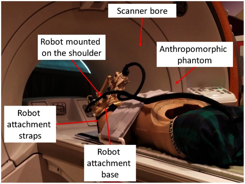
Anthropomorphic phantom studies were performed under intraoperative MRI guidance to evaluate the targeting accuracy of the integrated system inside a 1.5 Tesla Siemens Aera MRI scanner. Figure 6 shows the experiment setup. A needle is robotically aligned to the prescribed needle trajectory and then manually inserted into the phantom and imaged with diagnostic Proton Density-Turbo Spin Echo imaging protocol (; ; ; ; ). The experiments were conducted with eight targets on the left shoulder and seven targets on the right shoulder. For each needle insertion, the robot was registered to the scanner coordinate system and then the desired target and skin entry points were defined on the planning image set using 3-D Slicer.
Fig. 6.
Experimental setup showing the robot attached on the shoulder of an anthropomorphic phantom in the scanner bore for accuracy assessment.
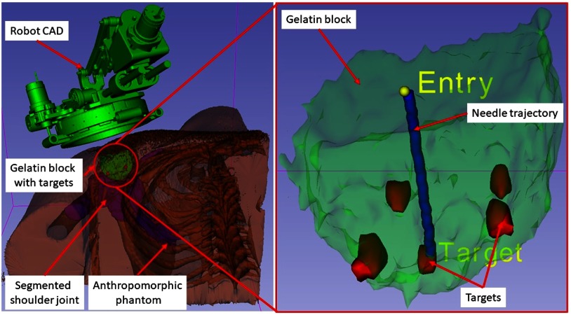
To assess the needle placement accuracy, more than 40 points are manually selected along the needle trajectory in the confirmation images and a line is fit to calculate the needle pose vector. The needle positioning accuracy is evaluated by measuring the minimum distance between the segmented needle trajectory and the prescribed target location, whereas the orientation accuracy is measured by calculating the Euler angles between the desired and measured needle pose vectors. Figure 7 shows one such target location and insertion trajectory obtained from the confirmation images. The experimental results are summarized for each of the targets in Table 3, with average positioning errors of 1.53, 0.67, and 0.95 mm in (right), (anterior), and (superior) directions, respectively, and average orientation errors of 1.24 deg and 0.62 deg about and axes, respectively. Errors for rotation about axis are not presented since that represented the needle rotation about its axis, which is performed manually and cannot be measured from the needle artifact in MR images. Using the registration algorithm described in Sec. 2.3, the average residual error for the registration frame used in this robot is . Also, we recorded start/end time shown on the robot control workstation for each phase of the clinical workflow during the targeting experiments. Figure 4 shows an average time for each of the workflow phases.
Fig. 7.
A 3-D Slicer scene for one of the targeting attempts showing on the left: segmented 3-D volume of the anthropomorphic phantom, embedded gelatin block for targeting, and robot CAD overlay and on the right: close-up view of the gelatin block, five target locations, planned target and entry points, and needle trajectory segmented form a confirmation image set.
Table 3.
Robot accuracy assessment results for the MRI phantom study: , , and are in millimeters, whereas , , and are in degrees.
| Tar. no. | Loc. | Planned target |
|
||||||
|---|---|---|---|---|---|---|---|---|---|
| 1 | L | −108.56 | 9.19 | −40.93 | 2.60 | 0.17 | 0.62 | 1.34 | 0.37 |
| 2 | L | −152.21 | 3.55 | −46.38 | 0.27 | 0.46 | 1.23 | 0.38 | 0.91 |
| 3 | L | −155.54 | −3.12 | −25.80 | 0.44 | 0.48 | 1.37 | 2.06 | 0.70 |
| 4 | L | −124.89 | 3.53 | −13.64 | 3.87 | 0.94 | 0.17 | 1.79 | 0.72 |
| 5 | L | −141.28 | −9.87 | −35.94 | 1.22 | 0.11 | 0.11 | 2.68 | 1.07 |
| 6 | L | −126.04 | 9.53 | −43.00 | 3.39 | 2.23 | 0.63 | 0.56 | 1.37 |
| 7 | L | −154.73 | −3.03 | −26.56 | 0.96 | 0.15 | 1.04 | 0.94 | 0.03 |
| 8 | L | −141.34 | −9.93 | −35.50 | 0.42 | 1.30 | 0.91 | 2.03 | 0.05 |
| 9 | R | 112.56 | 5.71 | −46.31 | 0.04 | 0.75 | 2.03 | 0.40 | 0.15 |
| 10 | R | 90.40 | 12.54 | −47.61 | 0.62 | 0.30 | 0.15 | 0.95 | 1.03 |
| 11 | R | 108.86 | −5.99 | −19.45 | 1.65 | 0.30 | 0.03 | 0.25 | 0.23 |
| 12 | R | 102.50 | −7.70 | −37.68 | 0.93 | 1.50 | 1.90 | 0.61 | 0.88 |
| 13 | R | 86.96 | −2.94 | −19.09 | 2.70 | 1.02 | 2.85 | 0.71 | 0.03 |
| 14 | R | 112.54 | 5.19 | −45.46 | 2.90 | 0.31 | 0.49 | 2.34 | 0.34 |
| 15 | R | 102.54 | −7.26 | −36.87 | 1.00 | 0.09 | 0.77 | 0.52 | 0.21 |
| Average | 1.53 | 0.67 | 0.95 | 1.17 | 0.54 | ||||
| STD | 1.24 | 0.62 | 0.81 | 0.80 | 0.44 | ||||
3.3. Magnetic Resonance Imaging Compatibility
MR environment poses challenges due to its high magnetic field strength and susceptibility to radio frequency (RF) noise. Such high magnetic field strength poses risk of a metallic object getting pulled into the bore and causing an injury or even death. Also, electronic devices operating in the MR environment could interfere with the scanner and deteriorate the image quality. The ASTM classifies the devices operating in MR environment into three categories, as described in ASTMS F2503: (1) MR safe, (2) MR conditional, and (3) MR unsafe. Also, ASTM specifies that the following tests should be conducted for device classification: (1) magnetically induced displacement force (Test Method F2052), (2) magnetically induced torque (Test Method F2213), and (3) RF-induced heating (Test Method F2182). In this work, as the presented robotic system does not come in direct contact with the patient body and is not an implantable device, the RF-induced heating test is not conducted.
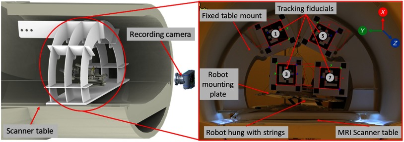
Experiments were performed to measure the magnetically induced displacement force and torque that could result in undesired robot motion. As shown in Fig. 8, the robot was hung with the support of strings such that it could freely move due to any induced force in a 1.5 T Siemens Aera scanner at Children’s National Medical Center in Washington DC. To measure the displacement and torque while performing the MRI, we attached multiple augmented reality markers29 to the fixed support frame and the robot mounting plate and tracked their position and orientation by a digital camera placed at an approximate distance of 2 m. We evaluated the setup for the scan sequence which we used in this study as well as for American College of Radiology (ACR) recommended test scan sequences ACR-T1 and ACR-T2. As shown in Fig. 8, markers 1 and 5 were attached on a fixed frame, whereas markers 3 and 7 were attached on the moving robot frame. Over the entire scan period, the standard deviations of the observed positions of the markers on the moving frame (markers 3 and 7) was 0.16 mm, 0.33 mm, and 1.06 mm in X, Y, and Z directions, respectively. These results confirm that there was no observable displacement or torque induced by the magnetic field while the scanner was running. We also considered whether the presence of the robot caused any image distortion or RF noise that deteriorated image quality. In our previous work, we evaluated the same control system with an earlier generation of the robot and we did not observe any distortion due to the presence of the robot, or any RF noise while the robot was off, as in our proposed workflow the robot is going to be powered off during the imaging.22
Fig. 8.
Experimental setup showing the robot hanging with the support of strings inside the scanner bore for performing ASTM tests: (1) magnetically induced displacement force (test method F2052), (2) magnetically induced torque (test method F2213).
4. Discussion
In this paper, we have reported development of an integrated robotic system for MRI-guided shoulder arthrography in pediatric patients. The presented system is an improved version of previous systems developed by our research groups.22,23 Each component of the system is improved over previous generations to improve the usability of the device in a clinical setting. Because the robotic device has a serial structure, cable movement during the operation of the robot has been problematic; this version optimizes the cabling which is essential for translating such a system for patient trials. Sterility plays an important role when it comes to using any system for human trials; in this system, we have improved the needle guide to maintain the sterile environment without making any major modifications to the clinical workflow for the manual procedure.
In this work we report an end-to-end evaluation of the system including benchtop and anthropomorphic phantom studies to assess the system accuracy and repeatability. The achieved accuracy of 0.9 mm in benchtop setting shows that the robot is accurate and repeatable for the targeted shoulder arthrography procedure. Also, the accuracy assessment in anthropomorphic phantom studies confirmed the end-to-end clinical workflow with an average positioning error of 1.92 mm. The accuracy of the robotic system described herein might be sufficient for targeting the shoulder joint space in pediatric patients. One of the factors in accuracy evaluation could be user error during manual segmentation of the needle trajectories; however, it is challenging to automatically segment the needle trajectory from MR images of nonhomogeneous tissue structures and is outside the scope of this paper as it primarily focuses on system development. Some of the other factors affecting the accuracy includes mechanism deformation, robot registration errors, and needle bending. This study has helped us identify some of the issues with the current system: (1) mounting the robot to the support base is difficult as it does not have any handles/mechanism to hold the robot, (2) the robot mounting does not have a locking mechanism to prevent it from coming off of the support base and, (3) backdrivable transmission of the needle guide could potentially create errors if the clinician applied too much force. In future we will improve the robot design to resolve these issues. Also, to reduce relative motion between the patient body and the robot base, we are working on improving the robot mounting mechanism,30 which could potentially be either straps-based or a shoulder brace to provide more support without causing patient discomfort. After implementing these modifications and further optimizing the clinical workflow, in future, we plan to perform a human cadaver study and then clinical trials.
5. Conclusions
This paper presents an integrated robotic system for intraoperative MRI-guided shoulder arthrography in pediatric patients. The integrated system consists of a compact 4-DOF robotic device, an embedded robot controller, robot control application, and needle trajectory planning application (3-D Slicer). Benchtop experiments were performed to evaluate the accuracy of the robotic device, whereas anthropomorphic phantom experiments were performed to evaluate the accuracy of the integrated system in MRI. Needle placement errors in benchtop experiments were found to be 0.90 mm and 1.04 deg, whereas in MRI experiments it was found to be 1.92 mm and 1.28 deg. Also, based on ASTM test results, the robotic device is classified as MR conditional. The needle placement accuracy in MRI phantom study shows that the presented system could be used clinically; in future, accuracy will be improved by replacing the 3-D printed robot parts with more rigid machined components. Other factors affecting accuracy include errors from robot registration, needle deflection, and target motion. In future work, we plan to develop a fully actuated robotic system providing needle insertion and rotation, to further assist the radiologist and potentially compensate for errors from needle deflection and target motion.
Acknowledgments
This work was funded by National Institutes of Health Grant No. 1RO1 EB020003-01. The authors would like to thank JHU undergraduate students Luke Robinson, for his help with robot controller assembly, and Justin Kim, for his help with robot mechanism assembly and testing. The authors would also like to thank Lu Vargas and Shena Philips, MR technologists at Children’s National Health System, who helped with the MRI studies.
Biographies
Niravkumar Patel is a postdoctoral fellow at the Laboratory for Computational Sensing and Robotics, Johns Hopkins University, Maryland. He received his bachelor’s degree in computer engineering from North Gujarat University, India, in 2005 and his MTech degree in computer science and engineering from Nirma University, India, in 2007. He received his PhD in robotics engineering from Worcester Polytechnic Institute, Massachusetts, in 2017. His current research interests include medical robotics, image-guided interventions, robot-assisted retinal surgeries, and path planning.
Jiawen Yan is currently a visiting scholar at Johns Hopkins University and a PhD candidate at Harbin Institute of Technology, China.
Reza Monfaredi is a mechanical engineer with expertise in medical device and robotic system design, control, and integration. He received his PhD from Amirkabir University of Technology, Iran. He joined Children’s National as a postdoctoral fellow in 2012 and was promoted to a staff scientist in 2013. His research is focused mainly on developing MRI-compatible robots in collaboration with Johns Hopkins University and rehabilitation robots.
Karun Sharma is a director of Interventional Radiology at Children’s National. He is an associate professor of pediatrics at the George Washington University School of Medicine and Health Sciences, Washington DC. He received his PhD and MD degrees from Virginia Commonwealth University School of Medicine, in 2001, and his BS degree in biology from William & Mary, Virginia, in 1992.
Kevin Cleary is the scientific lead for the Sheikh Zayed Institute for Pediatric Surgical Innovation at Children’s National Health System in Washington DC. His work focuses on developing biomedical devices for children, with special interest in MR-compatible robotics, rehabilitation robotics, and image-guided interventions. He received his BS and MS degrees from Duke University and his PhD from the University of Texas at Austin, all in mechanical engineering, followed by an NSF-sponsored postdoctoral in Japan.
Iulian Iordachita (IEEE M’08, S’14) is a faculty member of the Laboratory for Computational Sensing and Robotics, Johns Hopkins University, and the director of the Advanced Medical Instrumentation and Robotics Research Laboratory. He received his MEng degree in industrial robotics and PhD in mechanical engineering in 1989 and 1996, respectively, from the University of Craiova, Romania. His current research interests include medical robotics, image-guided surgery, robotics, smart surgical tools, and medical instrumentation.
Disclosures
Dr. Cleary, Dr. Monfaredi, and Dr. Sharma are inventors on PCT/US2014/042685 titled “Patient mounted MRI and CT compatible robot for needle guidance in interventional procedures.”
References
- 1.Patel N. A., et al. , “System integration and preliminary clinical evaluation of a robotic system for MRI-guided transperineal prostate biopsy,” J. Med. Rob. Res. 4(1), 1950001 (2018). 10.1142/S2424905X19500016 [DOI] [PMC free article] [PubMed] [Google Scholar]
- 2.Krieger A., et al. , “Development and evaluation of an actuated MRI-compatible robotic system for MRI-guided prostate intervention,” IEEE/ASME Trans. Mechatron. 18(1), 273–284 (2013). 10.1109/TMECH.2011.2163523 [DOI] [PMC free article] [PubMed] [Google Scholar]
- 3.Su H., et al. , “Piezoelectrically actuated robotic system for MRI-guided prostate percutaneous therapy,” IEEE/ASME Trans. Mechatron. 20(4), 1920–1932 (2015). 10.1109/TMECH.2014.2359413 [DOI] [PMC free article] [PubMed] [Google Scholar]
- 4.Eslami S., et al. , “In-bore prostate transperineal interventions with an MRI-guided parallel manipulator: system development and preliminary evaluation,” Int. J. Med. Rob. Comput. Assisted Surg. 12(2), 199–213 (2016). 10.1002/rcs.1671 [DOI] [PMC free article] [PubMed] [Google Scholar]
- 5.Stoianovici D., et al. , “MR safe robot, FDA clearance, safety and feasibility prostate biopsy clinical trial,” IEEE/ASME Trans. Mechatron. 22, 115–126 (2017). 10.1109/TMECH.2016.2618362 [DOI] [PMC free article] [PubMed] [Google Scholar]
- 6.Moreira P., et al. , “The MIRIAM robot: a novel robotic system for MR-guided needle insertion in the prostate,” J. Med. Rob. Res. 2, 1750006 (2017). 10.1142/S2424905X17500064 [DOI] [Google Scholar]
- 7.Masamune K., et al. , “Development of an MRI-compatible needle insertion manipulator for stereotactic neurosurgery,” J. Image Guided Surg. 1(4), 242–248 (1995). 10.1002/(ISSN)1522-712X [DOI] [PubMed] [Google Scholar]
- 8.Sutherland G. R., McBeth P. B., Louw D. F., “NeuroArm: an MR compatible robot for microsurgery,” Int. Congr. Ser. 1256, 504–508 (2003). 10.1016/S0531-5131(03)00439-4 [DOI] [Google Scholar]
- 9.Li G., et al. , “Robotic system for MRI-guided stereotactic neurosurgery,” IEEE Trans. Biomed. Eng. 62(4), 1077–1088 (2015). 10.1109/TBME.2014.2367233 [DOI] [PMC free article] [PubMed] [Google Scholar]
- 10.Kim Y., et al. , “Toward the development of a flexible mesoscale MRI-compatible neurosurgical continuum robot,” IEEE Trans. Rob. 33, 1386–1397 (2017). 10.1109/TRO.2017.2719035 [DOI] [PMC free article] [PubMed] [Google Scholar]
- 11.Yang B., et al. , “Design, development, and evaluation of a master–slave surgical system for breast biopsy under continuous MRI,” Int. J. Rob. Res. 33(4), 616–630 (2014). 10.1177/0278364913500365 [DOI] [PMC free article] [PubMed] [Google Scholar]
- 12.Larson B. T., et al. , “Design of an MRI-compatible robotic stereotactic device for minimally invasive interventions in the breast,” J. Biomech. Eng. 126(4), 458–465 (2004). 10.1115/1.1785803 [DOI] [PubMed] [Google Scholar]
- 13.Chan K. G., Fielding T., Anvari M., “An image-guided automated robot for MRI breast biopsy,” Int. J. Med. Rob. Comput. Assisted Surg. 12(3), 461–477 (2016). 10.1002/rcs.v12.3 [DOI] [PubMed] [Google Scholar]
- 14.Patel N. A., et al. , “Closed-loop asymmetric-tip needle steering under continuous intraoperative MRI guidance,” in 37th Annu. Int. Conf. Eng. Med. and Biol. Soc. (EMBC), IEEE, pp. 4869–4874 (2015). 10.1109/EMBC.2015.7319484 [DOI] [PubMed] [Google Scholar]
- 15.Guo J., et al. , “MRI-guided needle steering for targets in motion based on fiber Bragg grating sensors,” in IEEE SENSORS, pp. 1–3 (2016). 10.1109/ICSENS.2016.7808419 [DOI] [Google Scholar]
- 16.Walsh C. J., et al. , “A patient-mounted, telerobotic tool for CT-guided percutaneous interventions,” J. Med. Devices 2(1), 011007 (2008). 10.1115/1.2902854 [DOI] [Google Scholar]
- 17.Maurin B., et al. , “A patient-mounted robotic platform for CT-scan guided procedures,” IEEE Trans. Biomed. Eng. 55(10), 2417–2425 (2008). 10.1109/TBME.2008.919882 [DOI] [PubMed] [Google Scholar]
- 18.Bricault I., et al. , “Light puncture robot for CT and MRI interventions,” IEEE Eng. Med. Biol. Mag. 27(3), 42–50 (2008). 10.1109/EMB.2007.910262 [DOI] [PubMed] [Google Scholar]
- 19.Hungr N., et al. , “Design and validation of a CT-and MRI-guided robot for percutaneous needle procedures,” IEEE Trans. Rob. 32(4), 973–987 (2016). 10.1109/TRO.2016.2588884 [DOI] [Google Scholar]
- 20.Song S.-E., et al. , “Design evaluation of a double ring RCM mechanism for robotic needle guidance in MRI-guided liver interventions,” in IEEE/RSJ Int. Conf. Intell. Rob. and Syst. (IROS), IEEE, pp. 4078–4083 (2013). 10.1109/IROS.2013.6696940 [DOI] [Google Scholar]
- 21.Wu F. Y., et al. , “An MRI coil-mounted multi-probe robotic positioner for cryoablation,” in Proc. ASME Int. Des. Eng. Tech. Conf. and Comput. and Inf. Eng. Conf., pp. 1–9 (2013). [Google Scholar]
- 22.Monfaredi R., et al. , “A prototype body-mounted MRI-compatible robot for needle guidance in shoulder arthrography,” in 5th IEEE RAS & EMBS Int. Conf. Biomed. Rob. and Biomechatron., IEEE, pp. 40–45 (2014). 10.1109/BIOROB.2014.6913749 [DOI] [PMC free article] [PubMed] [Google Scholar]
- 23.Patel N. A., et al. , “Robotic system for MRI-guided shoulder arthrography: accuracy evaluation,” in Int. Symp. Med. Rob. (ISMR), IEEE, pp. 1–6 (2018). 10.1109/ISMR.2018.8333299 [DOI] [Google Scholar]
- 24.Monfaredi R., Cleary K., Sharma K., “MRI robots for needle-based interventions: systems and technology,” Ann. Biomed. Eng. 46(10), 1479–1497 (2018). 10.1007/s10439-018-2075-x [DOI] [PMC free article] [PubMed] [Google Scholar]
- 25.American Society of Testing and Materials (ASTM), “Standard practice for marking medical devices and other items for safety in the magnetic resonance environment,” ASTM F2503–13 (2005). [DOI] [PubMed]
- 26.Fedorov A., et al. , “3D slicer as an image computing platform for the quantitative imaging network,” Magn. Reson. Imaging 30(9), 1323–1341 (2012). 10.1016/j.mri.2012.05.001 [DOI] [PMC free article] [PubMed] [Google Scholar]
- 27.Tokuda J., et al. , “OpenIGTLink: an open network protocol for image-guided therapy environment,” Int. J. Med. Rob. Comput. Assisted Surg. 5(4), 423–434 (2009). 10.1002/rcs.v5:4 [DOI] [PMC free article] [PubMed] [Google Scholar]
- 28.Tokuda J., et al. , “Configurable automatic detection and registration of fiducial frames for device-to-image registration in MRI-guided prostate interventions,” Lect. Notes Comput. Sci. 8151, 355–362 (2013). 10.1007/978-3-642-38709-8 [DOI] [PMC free article] [PubMed] [Google Scholar]
- 29.Garrido-Jurado S., et al. , “Automatic generation and detection of highly reliable fiducial markers under occlusion,” Pattern Recognit. 47(6), 2280–2292 (2014). 10.1016/j.patcog.2014.01.005 [DOI] [Google Scholar]
- 30.Monfaredi R., et al. , “Shoulder-mounted robot for MRI-guided arthrography: accuracy and mounting study,” in 37th Annu. Int. Conf. IEEE Eng. Med. and Biol. Soc. (EMBC), IEEE, pp. 3643–3646 (2015). 10.1109/EMBC.2015.7319182 [DOI] [PubMed] [Google Scholar]


