Abstract
This work further advances the micromagnetic stimulation (μMS) technology, which has shown the capability of stimulating the nervous system using magnetic induction in a focal region of tissue by discharging a time-varying current through a sub-millimeter size coil. However, μMS was originally based on commercial off the shelf (COTS) inductors, which are designed to maximize efficiency and minimize its losses albeit shielding off the magnetic field from reaching the neural tissue. In this work, we study and fabricate microscale coil structures for next-generation μMS devices. The coil was designed to optimize the flux injected into the tissue by using a planar square spiral coil geometry, which was previously shown to be optimal for neuronal stimulation. The results of the electromagnetic Finite Elements Method (FEM) simulations of the proposed μMS device show that even though the spiral has a fully symmetric design, it nonetheless exhibits an asymmetry in the induced electric field in the tissue that can potentially be used for activating neurons with a specific axonal orientation. Such devices could become the brain and heart stimulators of the future with their contactless ability to deliver the neuronal stimulation needed for therapeutic efficacy in patients in need of implantable cardioverter-defibrillators or pace-makers, or patients with Parkinson’s disease, epilepsy.
Introduction
Micromagnetic stimulation (μMS) near excitable tissue induces a localized current gradient in both time and space adequate to activate neurons, as demonstrated in vitro by activating retinal ganglion cells [1]. We have also shown that μMS is capable of activating neuronal circuitry in-vivo in rodent models, using acutely implanted micro coils to activate neurons of the inferior colliculus [2]. These experiments have shown that μMS has the promise of introducing new paradigms in the stimulation of the human nervous system. Although electrical manipulation of neurons continues to evolve using novel electrode designs [3], μMS has several advantages over the traditional electrical stimulation: (1) it does not require charge-balanced stimulation waveforms, (2) it can activate neurons with specific axonal orientations, (3) it has improved biocompatibility when coated with implantable grade polymers, and (4) it is a potentially magnetic resonance imaging (MRI) compatible technology. The in-vitro studies [1] showed that μMS coils placed parallel to the surface of the tissue can activate neurons differentially based on coil orientation. Furthermore, previous electromagnetic simulations indicate that single-layer planar spiral geometries are more efficient in eliciting neural activation because they induce significantly higher electric fields (up to 5 folds) into the tissue compared to solenoidal or helical coils [4]. The quandary is that μMS technology, which was first developed in our laboratory [1, 2], was entirely based on commercial components off the shelf (COTS), which are readily available to researchers. However, COTS inductors are designed to maximize efficiency (Q-factor), which consists of trapping the generated magnetic field to minimize its losses. Unfortunately, this type of design reduces the magnetic flux into the tissue and thus greatly reduces the stimulation efficacy. Instead, the magnetic flux of single-layer planar spiral coils may directly expose the tissue without trapping the magnetic flux. In this work, we studied and fabricated preliminary prototypes of a square design version of micro-scale single-layer planar spiral coil structures as μMS devices. Furthermore, we studied electric field E distribution over space with numerical electromagnetic simulations. The neural activation function is proportional to the derivative of the E along the axon’s axis. The Neurons which oriented perpendicular to the long axis of the solenoid are more likely to be activated as they experience higher E.
Simulations
The finite element method (FEM) was used to study the electric field induced by a microscopic planar square spiral coil of 300μm×300μm×100μm. This design was the stencil wafer that we have constructed to ultimately manufacture the coil (see below). Magnetically induced eddy currents in the tissue were calculated by solving the equation below [5]:
Where A,Ø, ∝, ε and ω represent magnetic vector potential, electric scalar potential, permeability, permittivity, and the angular frequency, respectively. ANSYS Maxwell (ANSYS Canonsburg, PA, USA) was used to solve the T-Ω formulation of the Maxwell’s equations as conventionally performed in the study of transcranial magnetic stimulation [6, 7]. Electric field strength induced by the a μMS coil placed 50μm above the surface of the tissue (σ = 0.47 S/m) was calculated when the coil was fed excited with a 70 kHz sinusoidal current [1]. The geometric model consisting of the coil connected to a current source on top of a 1.6mm×1.6mm×400μm slab of tissue. The current in each turn was the same for all the simulations was set to the value of Ir = 1 A.
Materials and methods
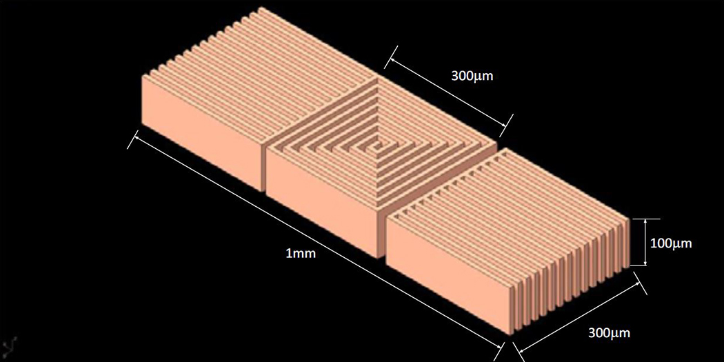
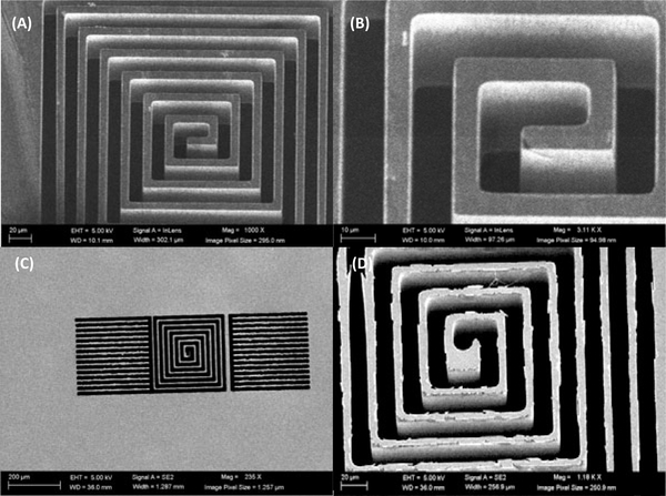
Fig. 1 illustrates a CAD drawing of the proposed single layer planar square spiral coil of dimensions 300μm×300μm×100μm which will be made from copper based on a 10μm trace width design. The two side structures around the spiral are simple pads that retain the 10μm trace width structure for uniformity, the lower pad will be connected to the center of the coil with a microwire. In Fig. 2 is shown Scanning Electron Microscope (SEM) images (Hitachi SU-8230) of a 100μm thin 100mm Si wafer (undoped, orientation <100> and > 5 kΩ-cm resistance). The SEM images were acquired after photolithography, and deep reactive ion etching (DRIE) performed at the Center for Nanoscale Systems at Harvard University. Photolithography was performed as follows: a 7μm thick layer of SPR 220–7 was spin coated on the thin wafer after hexamethyldisilazane (HMDS) deposition. This priming step was crucial for adhesion promotion, and the thin wafer was dehydrated through a series of heated (150°C) evacuation and dry nitrogen refills, followed by HMDS vapor inserted into the evacuated chamber forming a monolayer. The coated wafer was then exposed to a laser direct writing system (uPG501, Heidelberg Instruments Inc, Heidelberg, Germany) with a pattern shown in Fig. 1, and developed using AZ 400K for 4 minutes, without stirring. The wafer was then etched with a deep reactive ion etching system (DRIE-Rapier, SPTS Technologies, Newport, UK), which etched the thin wafer using Bosch switched processing for obtaining the steep vertical profiles (Fig. 2). The stencil wafer is still part of work in progress and will then be used to grow copper inside it using copper electroplating deposition.
Figure 1:

The proposed single layer planar square spiral coil of dimensions which is in copper based on a 10μm trace width. The side structures are simple pads that retain the 10μm trace width structure for uniformity.
Figure 2:
SEM images of the stencil wafer. Top view of the six turns single layer planar spiral coil (A), zoomed in view of the coil from the front (B), overview of the entire coil structure from the back side (C) after flipping the stencil wafer over showing that the DRIE reached through and through, and details of the back side of the stencil wafer that show a bottom footing (D).
Simulation results
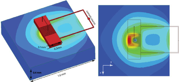
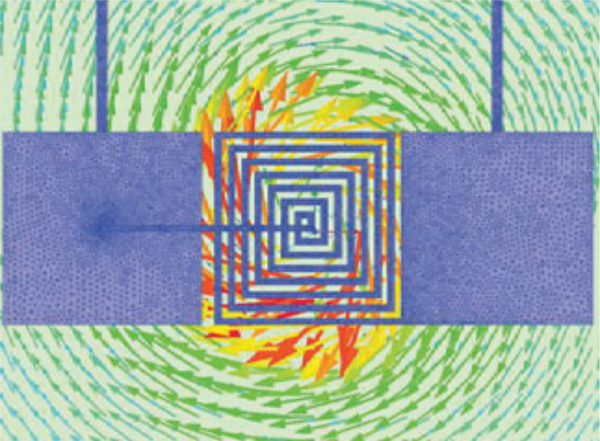
Fig. 3 shows the FEM results of the electric field induced in the tissue exhibits an asymmetry along the x-axis. This electromotive force estimated by the FEM simulations and induced by the magnetic flux of the coil (Fig. 4) has a component along mainly one axis, which could be exploited to activate axons with a specific orientation.
Figure 3:
The Finite Elements Method (FEM) Simulations. (Left) The geometric model consisting of the coil connected to a current source on top of a slab of tissue. (Right) The electric field induced in the tissue exhibits an asymmetry, which allows stimulating neurons along the direction of the x-axis.
Figure 4:
The induced eddy currents in the tissue generated by the μMS coil magnetic flux, which was estimated by the FEM simulations.
Conclusions
In this work, we studied using the Finite Elements Method (FEM) and fabricated microscale coil structures for next-generation μMS devices. The coil was a planar square spiral coil geometry, which was previously shown to be optimal for neuronal stimulation. The results of the FEM simulations show that even though the single layer planar spiral has a fully symmetric design, it has nonetheless exhibited an asymmetry in the induced electric field magnitude in the tissue that can be exploited for activating neurons with a specific directionality, one of the salient characteristics of μMS. This technology could become potentially the pacemaker and brain stimulator of the future given the μMS contactless ability to deliver the neuronal stimulation, which is needed for therapeutic efficacy in patients with Parkinson’s disease, epilepsy, in need of implantable cardioverter-defibrillators or pace-makers, etc.
Acknowledgments
We would like to thank Ian Webb and Laurence Calancea at the Harvard College for the assistance in manufacturing the stencil coil. This work was conducted with support from Harvard Catalyst | The Harvard Clinical and Translational Science Center (National Center for Research Resources and the National Center for Advancing Translational Sciences, National Institutes of Health Award UL1 TR001102, R01MH111875 and financial contributions from Harvard University and its affiliated academic health care centers). The content is solely the responsibility of the authors and does not necessarily represent the official views of Harvard Catalyst, Harvard University and its affiliated academic health care centers, or the National Institutes of Health”. This work was performed in part at the Center for Nanoscale Systems (CNS), a member of the National Nanotechnology Coordinated Infrastructure (NNCI), which is supported by the National Science Foundation under NSF award no. 1541959. CNS is part of Harvard University.
References
- [1].Bonmassar G, Lee SW, Freeman DK, Polasek M, Fried SI, and Gale JT, “Microscopic magnetic stimulation of neural tissue,” Nat Commun, vol. 3, p. 921, 2012. [DOI] [PMC free article] [PubMed] [Google Scholar]
- [2].Park HJ, Bonmassar G, Kaltenbach JA, Machado AG, Manzoor NF, and Gale JT, “Activation of the central nervous system induced by micro-magnetic stimulation,” Nat Commun, vol. 4, p. 2463, 2013. [DOI] [PMC free article] [PubMed] [Google Scholar]
- [3].Golestanirad L, Elahi B, Molina Arribere A, Mosig JR, Pollo C, and Graham SJ, “Analysis of fractal electrodes for efficient neural stimulation,” Frontiers in neuroengineering, vol. 6, p. 3, 2013. [DOI] [PMC free article] [PubMed] [Google Scholar]
- [4].Bonmassar G and Golestanirad L, “EM fields comparison between planar vs. solenoidal μMS coil designs for nerve stimulation,” in 2017 39th Annual International Conference of the IEEE Engineering in Medicine and Biology Society (EMBC), 2017, pp. 3576–3579. [DOI] [PMC free article] [PubMed] [Google Scholar]
- [5].Bonmassar G, Gale J, and Vanduffel W, “Optimizing Microscopic Magnetic Fields for Neuronal Stimulation,” International Journal of Bioelectromagnetism, vol. 16, pp. 1–31, 2014. [Google Scholar]
- [6].Golestanirad L, Mattes M, Mosig JR, and Pollo C, “Effect of model accuracy on the result of computed current densities in the simulation of transcranial magnetic stimulation,” IEEE Transactions on Magnetics, vol. 46, pp. 4046–4051, 2010. [Google Scholar]
- [7].Golestanirad L, Rouhani H, Elahi B, Shahim K, Chen R, Mosig JR, Pollo C, and Graham SJ, “Combined use of transcranial magnetic stimulation and metal electrode implants: a theoretical assessment of safety considerations,” Physics in medicine and biology, vol. 57, p. 7813, 2012. [DOI] [PubMed] [Google Scholar]


