

Abstract
In this work, a set of analytical expressions to tailor the numerical aperture of cone-shaped step optical fibers is proposed. The expressions are derived from the geometrical study of light-ray tracing at the cone-shaped tip of a regular step-index optical fiber. Analysis of the different physical phenomena that can take place at the tip of the fiber led to numerical apertures ranging from 0 to 1.5 which can be achieved via a variety of cone angles, providing great versatility in the design of light sources or light collecting devices based on step-index optical fibers.
Keyword: Optics
1. Introduction
The numerical aperture (NA) is a parameter to measure the capabilities of an optical system to gather light; the larger the NA, the wider the angle in which the system can accept light. When the optical system is utilized for illumination purposes, the NA tells the user about the emitting angle of the light projected by the imaging system. Likewise, the larger the NA, the wider the illumination angle.
In the case of optical fibers, the NA has the same meaning as in any optical system, telling about the capabilities of the optical fiber to gather and/or to emit light. In either case, gathering or emission of light, an optical fiber with the largest possible NA to guarantee the largest accepting or emitting cones of light is desired. As for the case of step index optical fibers, the numerical aperture is determined by the refractive index of the core and the cladding , namely , being the semi-angle of emission or gathering of light, and the refractive index of the surrounding medium. From this equation, it can be deducted that the difference between the refractive indexes must be maximized to have that largest possible NA. Commercially, ultra-high NA optical fibers are limited up to 0.35, which leads to a cone of acceptance or emission of the order of just 41. This figure could be quite small for many applications [1, 2, 3, 4]; therefore, different options have been utilized to increase the numerical aperture: photonic-crystal fibers [5, 6, 7], or shaped optical fibers [8, 9, 10]. In the former, the NA is increased thanks to an increment of the effective refractive index of the core. In the latter, the distal end of the optical fiber is geometrically modified.
Owing to the elaborated engineering process to produce photonics-crystal fibers, shaping is the most accessible method to increase the NA of the optical fibers. Multiple techniques have been reported to modify the geometry of the optical fiber tip; these include mechanical [11, 12, 13, 14], thermal [15], laser-aided [16, 17], and chemical etching processes [18, 19, 20, 21, 22, 23].
Despite of the great spectrum of applications of cone-shaped optical fibers [11, 20, 23, 24, 25] and the multiple options that have been reported to produce them [1, 2, 3, 4, 5, 6, 7], up to the best knowledge of the authors there has not been an in-depth analysis on how the geometry of the distal end of the optical fiber is linked to the NA. Only a brief description has been reported elsewhere [26], and a preliminary ray-tracing analysis that does not account for all the phenomena that can take place in the cone-shaped surface has been carried out in [27]. For this reason, in this work we present an analytical design to tailor the numerical aperture of cone-shaped step optical fibers which can be utilized as a guideline for their production.
2. Analysis
The numerical aperture demands an unambiguous definition of the angle as the light is gathered or emitted. In the case of cone-shaped optical fibers aimed to be used as illumination sources, is the angle measured with respect to the cone axis of the refracted-out ray in the core-surrounding medium interface, as illustrated in Fig. 1. For sake of simplicity, only the sagittal plane is represented in figure. A coarse light-ray analysis on this plane shows that the angle varies according to the phenomena that the incident ray on that cone-shaped surface suffers; (a) a simple refraction, (b) one total internal reflection, or (c) multiple total internal reflections. These cases are the phenomena that are finally controlled by the incident angle, of the incoming ray over the cone-shaped surface; this latter angle is measured as illustrated in Fig. 1. In the same figure, one can realize that the incident angle can be controlled by the semi-angle of the cone tip, , measured with respect to the optical axis of the step optical fiber. In summary, the NA, namely the angleif the fiber is immersed in a refractive index , can be engineered as a function of the semi-angle of the tip in a step optical fiber for each of the phenomena that can take place on the cone-shape surface.
Fig. 1.

Step optical Fiber with a cone-shaped tip. , and are the refractive indexes of the surrounding medium, the cladding, and the core, in that order. A ray incident on the cone-shaped surface can suffer, depending on , (a) a simple refraction, (b) one total internal reflection, or (c) multiple total internal reflections.
For the light to impinge at the cone-shaped surface, initially it must be guided by the step optical fiber. Since the mode coupling could significantly change the characteristics of the light propagating along the fiber, this proposed analytical study can be used only for short fiber lengths (a few meters in plastic optical fibers or few hundred of meters in silica optical fibers) [28, 29]. In consequence, a step-index optical fiber is considered in this study. The light guiding is only possible if a total internal reflection takes place at the core-cladding interface. This mandatory condition leads to the rule
| (1) |
with measured as shown in Fig. 1. Effective coupling and propagation of the launched beam at the input facet of the optical fiber is assumed. Upon these assumptions, any ray reaching the cone-shaped surface must impinge the core-cladding interface at most at the critical angle, which is only possible for rays within the acceptance angle of the of the optical fiber; namely for rays within the NA of step-index optical fibers. Light-ray guided in the optical fiber impinges on the cone-shaped surface at an angle of , which for the limit-case in Eq. (1) turns into
| (2) |
On the cone-shaped surface, the ray can suffer any of the three aforementioned phenomena which are analyzed in the following subsections. It should be emphasized that a propagated or guided ray undergoes one of the three phenomena depending exclusively on the angle of the cone-shaped surface with no dependence on the size of the illumination at the input facet of the optical fiber.
2.1. Simple refraction
In this first case, the light-ray at the cone-shaped surface should impinge at an angle such that it does not experience total internal reflection at the core-medium interface, as shown in Fig. 2, namely
| (3) |
Fig. 2.

Scheme of a cone-shaped step optical fiber with tapered tip at an angle α such that Under this condition the incident ray suffers a simple refraction at the cone-shaped surface.
Considering that the semi-angle of the cone-shaped tip must be
| (4) |
Eq. (4) expresses the angle of the cone-shaped step optical fiber in terms of the index of refraction of the core, the cladding, and the surrounding medium of the step optical fiber, something that is highly wanted in engineering. Now, to connect the cone-shaped angle with the numerical aperture , requires Snell's law to be applied at the core-medium interface, which can be expressed as
| (5) |
which after some algebra allows the numerical aperture for a cone-shaped step optical fiber with a tip angle to be expressed as
| (6) |
In Fig. 3, a plot of Eq. (6) for a commercial multi-mode step optical fiber (Thorlabs® FG025LJA, 1.4577 /, pure silica core/fluorine-doped silica cladding) surrounded by air is shown. From this figure, it can be seen that by tuning the angle of the cone-shaped optical fiber from to , numerical apertures ranging from 0 to 0.64 can be achieved.
Fig. 3.

Plot of NA vs. semi-angle α for a commercial multi-mode fiber FG025LJA with a cone-shaped such that
2.2. One total internal reflection
As for the case of one total internal reflection on the cone-shaped surface, the incident angle at ① must fulfill the condition given by
| (7) |
Once again, accounting for the fact that , to have one total internal reflection on the surface ①, the semi-angle of the cone-shape tip must be
| (8) |
After this total internal reflection on the cone-shaped surface ①, the light ray must be refracted out on the cone-shaped surface ②. For this refraction to happen at the core-medium interface, the cone semi-angle must be chosen such that the incident angle , see Fig. 4, fulfills the condition . From Fig. 4, or
Fig. 4.

Scheme of a cone-shaped step optical fiber with tapered tip at a semi-angle α such that Under this condition the incident ray suffers one total internal reflection on the cone-shaped surface ① and it is refracted out at the cone-shaped surface ②.
According to the latter expression, the condition is equivalent to:
| (9) |
Eqs. (8) and (9) determine the limits that the semi-angle of the cone-shaped tip must fulfill for the guided light-ray to suffer one single internal reflection and thereafter be refracted out from the cone-shaped step optical fiber, namely:
| (10) |
On applying Snell's law at the core-medium interface ② with the use of auxiliary angles shown in Fig. 4, the numerical aperture can be expressed as a function of the cone-shaped semi-angle as:
| (11) |
In Fig. 5, Eq. (8) is plotted for a commercial multi-mode fiber (Thorlabs FG025LJA) surrounded by air. Numerical apertures ranging from 0 to 1 can be achieved by tuning the angle of the cone-shaped optical fiber from to which shows the opportunity to obtain step optical fibers with actual high numerical apertures.
Fig. 5.

Plot of NA vs. semi-angle α for a commercial multi-mode fiber (Thorlabs FG025LJA) with a conical tip when
2.3. Multiple internal reflections
The third phenomenon that can arise at the cone-shaped tip of the step index optical fiber is the occurrence of multiple internal reflections. This manuscript presents the situation where only two internal reflections happen. The first total internal reflection happens at cone-shaped surface ① and the second on the cone-shaped surface ②. Thereafter, the light-ray is refracted out on the cone-shaped surface ①, as shown Fig. 6. For total internal reflection to occur on the cone-shaped surface ②, after being totally internally reflected at surface ①, the incident angle must fulfill the condition
| (12) |
Fig. 6.
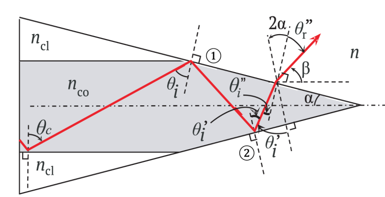
Scheme of a cone-shaped step optical fiber with tapered tip at a semi-angle α such that Under this condition the incident ray suffers one total internal reflection on the cone-shaped surface ①, one total internal reflection on the cone-shaped surface ②, and thereafter is refracted out at the cone-shaped surface ①.
Eq. (12) implies that as aforementioned for the case of a one total internal reflection.
Note that for the light-ray refracted out on the cone-shaped surface ①, cone semi-angle must be chosen such that the incident angle fulfills the condition . After some algebra with the geometry and the auxiliary angles illustrated in Fig. 6, one can arrive to the condition , which leads to an extra limit to the value of semi-angle cone-shaped tip
| (13) |
Thus, the limits that the semi-angle cone-shaped tip must fulfill for the light-ray guided ray to suffer two internal reflections and thereafter being refracted out from the cone-shaped step optical fiber are given by
| (14) |
Again, using Snell's law at the core-medium interface ② with the auxiliary angles shown in Fig. 6, the numerical aperture in this case is expressed as a function of the semi-angle cone-shaped as
| (15) |
The equations that have been derived in this paper also show the opportunity to surround the cone-shape optical fiber with mediums with higher refractive indexes than air to increase even further the achieved numerical apertures. To use this possibility, Eq. (15) has been plotted for a multi-mode fiber (Thorlabs FG025LJA) surrounded by different mediums, air (n = 1), water (n = 1.33), and immersion oil for microscopy (n = 1.515). Results are shown in Fig. 7. In this particular case, it can be noted that by choosing the angle of the cone-shaped optical fiber from to, numerical apertures up to 0.77 for air, up to 1.12 for water, and up to 1.31 for immersion oil can be achieved, providing great versatility in the design of this kind of light sources or light collecting devices. As was expected, the surrounding of the cone-shape optical fiber with mediums with refractive indexes higher than one leads to the very wanted option of numerical apertures also higher than one, a feature very much wanted in many applications.
Fig. 7.

The plot of NA versus α for the commercial multi-mode fiber Thorlabs FG025LJA with tapered tip at an angle α such .
The results of the carried out geometrical analysis that allowed Eq. (6), Eq. (11), and Eq. (15) to be obtained, allow a generalization to be made for the case of more than two total internal reflections. After a said number of total internal reflections, the numerical aperture, expressed as a function of the semi-angle cone-shaped , can be written as
| (16) |
Where . For a value of , this equation is valid for the range of values that satisfy the condition:
| (17) |
The parametric Eq. (16) can be used to design cone-shaped optical fibers with a specific numerical aperture after the light-ray being totally internal reflected times. Fig. 8 shows the NA for a commercial multi-mode fiber (Thorlabs FG025LJA) surrounded by air, vs. semi-angle , whose ranges of values are determined for the total internal reflections of = 0, = 1, = 2 and = 3, according to the condition imposed by Eq. (17). It can be seen that it is possible to obtain the same numerical aperture for different cone angles. The number is chosen at the designer's convenience. A number corresponds with cone tips with large angles, allows the largest numerical apertures to be achieved, while and exhibit changes dramatically in the numerical aperture with small variations of the cone angle, and therefore, a precise control in the cone fabrication would be required to ensure the desired value of NA.
Fig. 8.

Plot of NA vs. semi-angle for a commercial multi-mode fiber (Thorlabs FG025LJA) surrounded by air.
3. Conclusions
A simple and compact design equation to tailor the numerical aperture of cone-shaped optical fibers was presented in this work. This parametric equation can be used to design illumination sources or light gathering systems based on cone-shaped optical fibers with a specific numerical aperture. According to the analytic design, cone-shaped optical fibers with numerical apertures up to 1 for air, up to 1.33 for water, and up to 1.5 for immersion oil can be achieved from the convenient selection of the cone angle.
The presented design equations provide the production of a cone-shaped optical with a given numerical aperture through a variety of cone semi-angles. This feature allows the user to select the angle that fits better with the design needs according to the manufacturing capabilities available.
Declarations
Author contribution statement
Brayan Patiño-Jurado: Conceived and designed the experiments; Performed the experiments; Analyzed and interpreted the data; Contributed reagents, materials, analysis tools or data; Wrote the paper.
Juan F. Botero-Cadavid, Jorge Garcia-Sucerquia: Analyzed and interpreted the data; Contributed reagents, materials, analysis tools or data; Wrote the paper.
Funding statement
This work was supported by Convocatoria nacional para el apoyo al desarrollo de tesis de posgrado o de trabajos finales de especialidades en el área de la salud, de la Universidad Nacional de Colombia 2017-2018 and Colciencias through the calling 761 of 2016 –Program of Young Researchers.
Competing interest statement
The authors declare no conflict of interest.
Additional information
No additional information is available for this paper.
References
- 1.Allen P.C., Chen X., Holmgren D.E., Howells S.C. 2002. Electron Beam Column Using High Numerical Aperture Photocathode Source Illumination. US6448568B1. [Google Scholar]
- 2.Wadsworth W.J. Very high numerical aperture fibers. IEEE Photonics Technol. Lett. Mar. 2004;16(3):843–845. [Google Scholar]
- 3.Dudley J.M., Genty G., Coen S. Supercontinuum generation in photonic crystal fiber. Rev. Mod. Phys. Oct. 2006;78(4):1135–1184. [Google Scholar]
- 4.Maslov K., Stoica G., Wang L.V. In vivo dark-field reflection-mode photoacoustic microscopy. Opt. Lett. 2005 doi: 10.1364/ol.30.000625. [DOI] [PubMed] [Google Scholar]
- 5.Joannopoulos J.D., Johnson S.G., Winn J.N., Meade R.D. Princeton university press; 2011. Photonic Crystals: Molding the Flow of Light. [Google Scholar]
- 6.Knight J.C. Photonic crystal fibres. Nature. 2003;424(6950):847. doi: 10.1038/nature01940. [DOI] [PubMed] [Google Scholar]
- 7.Birks T.A., Knight J.C., Russell P.S.J. Endlessly single-mode photonic crystal fiber. Opt. Lett. 1997 doi: 10.1364/ol.22.000961. [DOI] [PubMed] [Google Scholar]
- 8.Town G.E., Lizier J.T. Tapered holey fibers for spot-size and numerical-aperture conversion. Opt. Lett. 2001 doi: 10.1364/ol.26.001042. [DOI] [PubMed] [Google Scholar]
- 9.Verdaasdonk R.M., Borst C. Ray tracing of optically modified fiber tips. 1: spherical probes. Appl. Opt. 1991;30(16):2159–2171. doi: 10.1364/AO.30.002159. [DOI] [PubMed] [Google Scholar]
- 10.Verdaasdonk R.M., Borst C. {R}ay tracing of optically modified fiber tips. 2: laser scalpels. Appl. Opt. 1991 doi: 10.1364/AO.30.002172. [DOI] [PubMed] [Google Scholar]
- 11.Betzig E., Lewis A., Harootunian A., Isaacson M., Kratschmer E. Near field scanning optical microscopy (NSOM): development and biophysical applications. Biophys. J. 1986 doi: 10.1016/S0006-3495(86)83640-2. [DOI] [PMC free article] [PubMed] [Google Scholar]
- 12.Garcia-Parajo M., Cambril E., Chen Y. Simultaneous scanning tunneling microscope and collection mode scanning near-field optical microscope using gold coated optical fiber probes. Appl. Phys. Lett. 1994;65(12):1498–1500. [Google Scholar]
- 13.Yakobson B.I., Moyer P.J., Paesler M.A. Kinetic limits for sensing tip morphology in near-field scanning optical microscopes. J. Appl. Phys. 1993 [Google Scholar]
- 14.Hoffmann P., Dutoit B., Salathé R.P. Comparison of mechanically drawn and protection layer chemically etched optical fiber tips. Ultramicroscopy. 1995;61(1–4):165–170. [Google Scholar]
- 15.Valaskovic G.A., Holton M., Morrison G.H. Parameter control, characterization, and optimization in the fabrication of optical fiber near-field probes. Appl. Opt. 1995 doi: 10.1364/AO.34.001215. [DOI] [PubMed] [Google Scholar]
- 16.Ran Z.L., Rao Y.J., Liu W.J., Liao X., Chiang K.S. Laser-micromachined Fabry-Perot optical fiber tip sensor for high-resolution temperature-independent measurement of refractive index. Optic Express. 2008 doi: 10.1364/oe.16.002252. [DOI] [PubMed] [Google Scholar]
- 17.Taylor R.S., Hnatovsky C., Simova E., Rayner D.M., Bhardwaj V.R., Corkum P.B. Femtosecond laser fabrication of nanostructures in silica glass. Opt. Lett. Jun. 2003;28(12):1043. doi: 10.1364/ol.28.001043. [DOI] [PubMed] [Google Scholar]
- 18.Ju Y., Kobayashi T., Soyama H. Vol. 1. 2007. Fabrication of a GaAs microwave probe used for atomic force microscope; pp. 963–966. (ASME 2007 InterPACK Conference). [Google Scholar]
- 19.Nikbakht H., Latifi H., Oraie M., Amini T. Fabrication of tapered tip fibers with a controllable cone angle using dynamical etching. J. Light. Technol. 2015;33(23):4707–4711. [Google Scholar]
- 20.Lambelet P., Sayah A., Pfeffer M., Philipona C., Marquis-Weible F. Chemically etched fiber tips for near-field optical microscopy: a process for smoother tips. Appl. Opt. Nov. 1998;37(31):7289. doi: 10.1364/ao.37.007289. [DOI] [PubMed] [Google Scholar]
- 21.Barucci A. Optical fibre nanotips fabricated by a dynamic chemical etching for sensing applications. J. Appl. Phys. 2015 [Google Scholar]
- 22.Burgos P. Near-field scanning optical microscopy probes: a comparison of pulled and double-etched bent NSOM probes for fluorescence imaging of biological samples. J. Microsc. 2003 doi: 10.1046/j.1365-2818.2003.01197.x. [DOI] [PubMed] [Google Scholar]
- 23.Sayah A., Philipona C., Lambelet P., Pfeffer M., Marquis-Weible F. Fiber tips for scanning near-field optical microscopy fabricated by normal and reverse etching. Ultramicroscopy. Mar. 1998;71(1–4):59–63. doi: 10.1364/ao.37.007289. [DOI] [PubMed] [Google Scholar]
- 24.Chang C.T., Auth D.C. Radiation characteristics of a tapered cylindrical optical fiber. J. Opt. Soc. Am. 1978;68(9):1191–1196. [Google Scholar]
- 25.Buratto S.K. Near-field scanning optical microscopy. Curr. Opin. Solid State Mater. Sci. 1996 [Google Scholar]
- 26.Schürmann M. Digital in-line holographic microscopy with various wavelengths and point sources applied to static and fluidic specimens. Physics. 2007 College. Park. Md. [Google Scholar]
- 27.Patiño-Jurado B., Botero-Cadavid J.F., García-Sucerquia J. 2018. Analysis of the Dependence of the Numerical Aperture on Cone Angle in a Tapered Step-index Optical Fiber. [Google Scholar]
- 28.Savović S., Kovačević M.S., Djordjevich A., Bajić J.S., Stupar D.Z., Stepniak G. Mode coupling in low NA plastic optical fibers. Optic Laser. Technol. 2014 doi: 10.1364/AO.53.006999. [DOI] [PubMed] [Google Scholar]
- 29.Djordjevich A., Savović S., Tse P.W., Drljaca B., Simović A. Mode coupling in strained and unstrained step-index plastic optical fibers. Appl. Opt. 2010 doi: 10.1364/AO.49.005076. [DOI] [PubMed] [Google Scholar]