

Abstract
Magnetic electrospun fibers are of interest for minimally invasive biomaterial applications that also strive to provide cell guidance. Magnetic electrospun fibers can be injected and then magnetically positioned in situ, and the aligned fiber scaffolds provide consistent topographical guidance to cells. In this study, magnetically responsive aligned poly-L-lactic acid electrospun fiber scaffolds were developed and tested for neural applications. Incorporating oleic acid-coated iron oxide nanoparticles significantly increased neurite outgrowth, reduced the fiber alignment, and increased the surface nanotopography of the electrospun fibers. After verifying neuron viability on two-dimensional scaffolds, the system was tested as an injectable three-dimensional scaffold. Small conduits of aligned magnetic fibers were easily injected in a collagen or fibrinogen hydrogel solution and repositioned using an external magnetic field. The aligned magnetic fibers provided internal directional guidance to neurites within a three-dimensional collagen or fibrin model hydrogel, supplemented with Matrigel. Neurites growing from dorsal root ganglion explants extended 1.4–3× farther on the aligned fibers compared with neurites extending in the hydrogel alone. Overall, these results show that magnetic electrospun fiber scaffolds can be injected and manipulated with a magnetic field in situ to provide directional guidance to neurons inside an injectable hydrogel. Most importantly, this injectable guidance system increased both neurite alignment and neurite length within the hydrogel scaffold.
Keywords: magnetic electrospun fibers, topographical guidance, injectable, poly-l-lactic acid, spinal cord injury, dorsal root ganglia
Graphical Abstract
1. INTRODUCTION
Biomaterial-based approaches to regenerative medicine are often designed to mimic the structure of the native extracellular matrix.1,2 Electrospinning has emerged as a powerful tool to create fibrous structures with a high surface-area-to-volume ratio that can be easily modified to deliver stem cells, drugs, or gene therapy to the local regenerating tissue environment.1–4 In the central nervous system, highly aligned electrospun fibers mimic the aligned structure of myelinated axon white matter tracts. Hurtado and colleagues established that scaffolds with highly aligned electrospun fibers achieved more robust, directed regeneration of axons than scaffolds with randomly oriented fibers in a spinal cord injury (SCI) model in vivo.5
While studies show that aligned fiber conduits promote regeneration, most studies are only able to maintain directional fiber alignment by using invasive open surgical techniques to implant rigid scaffolds into complete or incomplete transection models of spinal cord injury (SCI). Accessing the spinal cord requires a laminectomy to expose the spinal canal. This open surgery can increase the risk of infection and may sever undamaged white matter tracts within the spinal cord.6–8
The most common minimally invasive biomaterial approach is to inject a hydrogel that fills the irregular shape of the injury site.8–10 However, recent attempts to inject electrospun fibers within a hydrogel were unable to maintain fiber alignment.11–14 Three studies have proposed the use of magnetic assistance to create an anisotropic structure in situ. A decade ago, Kriha et al. proposed using 50–100 μm long single magnetic electrospun fibers to connect individual neurons in culture media in vitro.15 Recently, a similar approach was developed that used beds of short, 10 μm long magnetic microgels16 or 50 μm individual electrospun fibers17 to provide directional guidance within the injected fibrin hydrogel. These studies found that the anisotropy provided some guidance to neurites extending from dorsal root ganglia (DRGs) in vitro. However, these studies used short segments, which provided interrupted topography to cells and showed weak material magnetic responses to an applied field. The low magnetic response limited their application to low-viscosity solutions such as culture media15 or fibrinogen.16 Therefore, there is an opportunity for strategies that enable injection and orientation of longer (millimeter-scale) fibers within a higher-viscosity medium to provide continuous topographical guidance to improve neurite outgrowth.
Studies with electrospun fibers have shown that the continuous topography provided by electrospun fiber scaffolds is important for neurite guidance.5,18 In the current study, we prepared electrospun fiber composites by incorporating superparamagnetic iron oxide nanoparticles (SPIONs) into poly-L-lactic acid (PLLA) fibers. To address the continuity limitations observed in previous studies, we prepared 3000–5000 μm long injectable electrospun fibers and tested their ability to move in viscous hydrogel solutions. Superparamagnetic materials are advantageous over ferromagnetic materials because they are magnetically responsive only when activated by an external magnetic field. SPIONs are biocompatible and are used as a source of iron by local cells.19 SPIONs are widely used as contrast agents for imaging, tissue soldering, and tumor hyperthermia ablation.20,21 Concerns that the composite may release toxic levels of iron oxide nanoparticles are mitigated by using a slow degrading polymer, PLLA.22 Kriha et al. previously produced magnetic electrospun fibers with 0.8 wt % cobalt magnetic nanoparticles;15 Rose et al. created microgels with 0.011% SPION by volume; and Omidinia-Anarkoli et al. created fibers with 10% w/w SPIONs to PLGA.17 The magnetic response of the fibers may be improved by incorporating more SPIONs; however, it is still unknown how increasing the SPION content in the electrospinning solution may affect the resulting electrospun fibers. One of the goals of this study was to investigate how SPION incorporation affected fiber magnetization and topographical parameters known to affect neurite guidance.
To thoroughly characterize the effect of SPION content on the fiber topography and magnetization, four groups of electrospun fiber scaffolds were prepared with incrementing SPION concentrations (2, 4, 6, and 8 wt % SPION/PLLA). We hypothesized that the increased SPION content in the electrospinning solution would produce electrospun fibers that could be oriented more rapidly in a viscous solution compared with the fibers with the lowest SPION content (2%), without significant changes in topography. The magnetic response was tested using a vibrating sample magnetometer, followed by timed rotation of scaffolds in glycerol, fibrinogen, and collagen solutions. The fiber topography was analyzed using scanning electron microscopy (SEM) and transmission electron microscopy (TEM). Scaffold biocompatibility and guidance capability were then analyzed with dissociated primary rat neurons. Next, we hypothesized that the magnetically controlled electrospun fibers would guide neurite outgrowth in the direction of the oriented fibers within a fibrin or collagen hydrogel. To test this hypothesis, electrospun fiber conduits were injected into a collagen or fibrinogen solution supplemented with Matrigel and aligned to provide directional guidance to a rat dorsal root ganglion explant in a three-dimensional (3D) growth environment.
2. MATERIALS AND METHODS
2.1. Preparation of Magnetic Electrospun Fibers
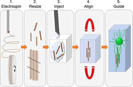
A general schematic is presented to show the methods used to create injectable fiber scaffolds (Figure 1A–E). Resulting scanning electron microscopy (SEM) images show the length of the scaffold, the edge of the scaffold, and the aligned fibrous structure of the scaffolds (Figure 1F–I). Electrospun fibers were prepared using a base solution of 8 wt % PLLA/chloroform. Superparamagnetic iron oxide nanoparticles (SPIONs) were incorporated at 2, 4, 6, and 8% of the weight of PLLA. The control (0%) was prepared without SPIONs. To prepare a 6% SPION electrospinning solution, for example, 14.4 mg of SPIONs (11–12 nm diameter with an oleic acid surface coating23) was weighed and added into a 4 dram borosilicate vial (66013–080, VWR, Philadelphia, PA) using an XS-64 balance (Mettler-Toledo, Columbus, OH). Then, 3 g of chloroform (288306, Sigma-Aldrich, St. Louis, MO) was weighed into the vial using an adventurer pro balance (AV213C, Ohaus, Pine Brook, NJ). The solution was capped and swirled on a VWR Mini Shaker (97109–892, VWR, Philadelphia, PA) rotating at 250 rpm until the particles were suspended in the chloroform (~1 min). When the SPIONs were suspended, 240 mg of high-molecular-weight PLLA (Ingeo biopolymer 6201D, Nature-Works, Blair, NB) was weighed using the XS-64 balance and added to the solution. The solution was rotated at 250 rpm on the Mini Shaker until PLLA was fully dissolved. Immediately before electrospinning, the solutions were sonicated in a water bath using a Bransonic ultrasonic cleaner (2510R-MTH, Branson, Danbury, CT) for 5 min. The oleic acid coating, shaker speed, and sonication treatment were all selected to improve particle distribution in the electrospinning solution.
Figure 1.

(A) Oleic acid-coated superparamagnetic iron oxide nanoparticles are mixed into the 8% PLLA electrospinning solution and chloroform by constant agitation. Once dissolved, the solution is electrospun onto a rotating mandrel to create an aligned fiber mat. (B) Mat is removed from the wheel and cut into approximately 3 mm × 5 mm segments. Using forceps, the fiber mats are carefully rolled into a small conduit that fits through the inner bore of the needle. (C) Small conduits and hydrogel are injected into a chamber. (D) Magnetic field is applied to orient the fibers within the hydrogel in situ until the hydrogel is solidified. (E) Magnetic field is removed, and the fibers remain aligned, supported by the hydrogel, to guide neurites extending from the dorsal root ganglion. (F–I) Scanning electron microscopy images of a 6% SPION fiber conduit. Scales bars: (F, G) 200 μm, (H) 100 μm, and (I) 10 μm.
Electrospinning was performed using previously published methods.24 The specific controlled parameters during electrospinning were as follows: 3.0 mL/h pump rate, 1000 rpm rotation speed, 10 min collection time, 10 kV voltage drop, 32–33% humidity, 20–23 °C temperature, and a 5 mm gap distance between the needle and the grounded collector. Adjustments to the electrospinner were made to accommodate the 8% SPION electrospinning solution. The gap distance was increased to 8 mm for the 8% SPION solutions because the fibers did not solidify when they impacted the wheel at the 5 mm gap distance.
2.2. Magnetic Fiber Analysis
2.2.1. Scanning Electron Microscopy of Fibers
Scanning electron microscope (SEM) imaging and fiber analysis were carried out using previously published methods.25 Briefly, samples were sputter-coated with 5 nm of platinum (Technics Hummer V sputter coater) and imaged using a Versa 3D SEM (FEI Hillsboro, OR). Images were taken using an acceleration voltage of 2 kV, a working distance of 10 mm, and a magnification of 1000×. For each sample, five images (see Figure S4) were taken at four corners and in the center of the coverslip (15 × 15 mm2; Knittel Glass, Braunschweig, Germany).
2.2.2. Quantification of Fiber Diameter and Alignment
SEM images were analyzed for fiber diameter using FIJI software (NIH, Bethesda, MD). The diameters of at least 70 individual fibers (approximately 14 fibers per image) were recorded from each of three independently fabricated samples for each condition (n = 3) by measuring the length of a line drawn perpendicular to each fiber’s alignment. The data was reported as a mean ± standard deviation. Fiber alignment was measured, using the same SEM images, by recording the angle by which each fiber deviated from the median fiber alignment. A line was drawn along the edge of each fiber with FIJI software. The angle of at least 70 individual fibers was measured for each group. Each group was normalized by determining the median fiber alignment for the group and reporting each fiber’s angle deviation from that median angle. The results were tabulated using SigmaPlot 11.0 (Systat Software, San Jose, CA) and reported as a histogram of the angle deviation from the median with 10° bins (Figure 3). Statistical analysis of fiber alignment was performed with JMP software (SAS, Cary, NC). A Brown–Forsythe test was used to compare the changes in variation between the groups.
Figure 3.

Fiber diameter (A) as a function of SPION concentration. The * denotes a significant increase in fiber diameter (p ≤ 0.05) of the 8% SPION fiber compared to that of the 0% control. Histograms of fiber alignment (B–F) as a function of angle deviation from the median fiber orientation, set to 0. The * indicates significantly decreased fiber alignment from the 0% control using a Brown–Forsythe test (p < 0.05). The effect of SPION increasing concentration was examined by plotting the standard deviations from each group against the SPION concentration (G). For each group, n = 3.
2.2.3. Transmission Electron Microscope Fiber Analysis
Transmission electron microscope (TEM) samples were prepared by electrospinning 0, 2, 4, 6, and 8 wt % SPION/PLLA fibers directly onto carbon type-B 300 mesh copper grids (01813-F, Ted Pella, Redding, CA). TEM images were obtained with a JEOL-1200 EX II 120 kV instrument (JEOL USA, Peabody, MA). The particle sizes in each group were measured using FIJI software.
2.2.4. Vibrating Sample Magnetometer Magnetization Characterization
The magnetic properties of the 2, 4, 6, and 8% SPION/PLLA composites were analyzed using a vibrating sample magnetometer (7400-S Series, Lake Shore Cryotronics Inc.). The experiment was preceded by calibration with a nickel standard (730908, 6.92 emu at 5000 Gauss, Lake Shore). For each group, three independently fabricated bundles of fibers (~12 mg each, n = 3) were loaded into the Kel-F sample holder (730931, Lake Shore) between two 2.5 in. pickups spaced 1 in. apart. Then, 200 points were measured as the field was ramped between 10 and −10 kOe at a rate of 20.1 Oe/s. The magnetic hysteresis loop was obtained by plotting the magnetic moment against the applied magnetic field. Each measured sample was normalized by the sample mass to obtain the magnetization (emu/g). The magnetization of the empty sample holder was removed from the data during calibration. To compare the values with the SPION-only values, the sample holder was measured with 0% SPION fibers. The saturation magnetization values were calculated by averaging the highest 30 points in the linear range of the magnetization curves. Data was analyzed using SigmaPlot 11.0.
2.3. Fiber Conduit Realignment Test
An experiment was developed to determine how each of the SPION-containing fiber scaffolds (2, 4, 6, and 8%) would respond to a magnetic field. Fibers were cut into 12 mm long segments. The fibers were submerged in a 50% glycerol (G2289, Sigma) and 50% water solution until testing. The glycerol solution was used as an inexpensive way to increase the solution viscosity while testing the reorientation rates of the different groups. Then, 4.0 mL of the 50% glycerol/water was measured and added into 1 well of a 12-well tissue culture dish (40–229112, CellTreat, Shirley, MA) and two 0.5 in. neodymium magnets (BHmax = 48 MGOe, ND025-N48, Applied Magnets, Plano, TX) were placed on either side of the experimental well to establish a magnetic field within the well, along which the fibers align. Each fiber sample was submerged in the well and oriented perpendicular to the field using forceps. Reorientation times were determined from the video taken using Canon Rebel T2i (Canon, Melville, NY). The time started when the forceps were removed from the sample, and the time was stopped when the fibers were oriented parallel to the field. The results represent the length of time that was required for the samples to rotate 90°. Because there was some variation in the experimental repeats, each data point represents the average of two samples cut from three independently fabricated SPION-fiber groups. Each sample was tested six times for reorientation. Therefore, each data point represents 36 measurements from three independently produced fiber groups.
2.3.1. Magnetic Fiber Alignment at Different Viscosities
To test the effects of solution viscosity on fiber realignment rates, dilutions of 25, 50, 75, and 100% glycerol solutions by volume were prepared in water. All solutions were measured in a DV2T system with a Wells–Brookfield viscometer attachment (Brookfield AMETEK, Middleboro, MA) at 21 °C. The rotation speed of the cone was adjusted to achieve a torque value as close to 100 as possible. The previously discussed 2.0 mg/mL collagen solution and 10 mg/mL fibrinogen solutions were also tested with the viscometer. Three replicates were prepared for all solutions. Realignment tests for each solution were performed according to the procedures described in Section 2.3 and plotted against the measured viscosity to assess how well the realignment times in the glycerol standard curve matched those in the fibrinogen and collagen solutions.
2.4. Magnetic Fiber/Hydrogel Injection and Orientation Video
The electrospun fiber mats were cut into small 5–6 mm segments and carefully rolled into conduits (Figure 1). The conduits were loaded into the inner bore of a 22G needle (305159, BD Biosciences, Franklin Lakes, NJ) with forceps. This method was inspired by the endoscopic techniques for minimally invasive stent delivery. The needle was attached to a 5 mL Syringe (309646, BD) loaded with 1 mL of collagen solution. Then, 4.6 μL of 1 N NaOH was pipetted into the well to neutralize the collagen when it entered the well. A small stand was made to lift the chamber so that it is centered in the magnetic field. Video was taken using Cannon Rebel T2i mounted on a tripod. The fibers were injected with the collagen into the 8 mm poly(dimethylsiloxane) (PDMS) chamber in the magnetic field and allowed to realign with the field. The chamber was transferred to the 37 °C incubator for 30 min to allow the collagen to polymerize. After polymerization, the video was resumed. The chamber was rotated 90° in the magnetic field to show that the 6% SPION fibers were locked in place in the hydrogel/fiber composite. This procedure was repeated using the 10 mg/mL fibrinogen solution. The 6% SPION fibers were chosen here because they provided the fastest magnetic response without significantly altering the fiber alignment and diameter compared to the 0% SPION control.
2.5. Dorsal Root Ganglion Isolation
The dorsal root ganglion (DRG) isolation protocol followed NIH Guidelines for the Care and Use of Laboratory Animals and was approved by the Institutional Animal Care and Use Committee (IACUC) at Rensselaer Polytechnic Institute. DRGs were isolated from P2 Sprague Dawley Rat pups (SD-FL 101A NTac:SD, Taconic Biosciences, Hudson, NY) according to previously published procedures.26 Care was taken to remove the fibrous capsule from the DRG to allow neurites to extend. DRGs were stored in F12 media (11765–047, Gibco) on ice until they were dissociated or plated.
2.6. Single-Neuron Isolation
Primary neurons were cultured on the fiber scaffold surfaces to measure how the SPION content in fibers may affect neuron survival and neurite elongation. Primary neurons were dissociated from P2 Sprague Dawley rat DRG using a modified process described by Koppes et al.27 Isolated DRGs were digested in a 37 °C buffer of 0.1% trypsin (25–054-Cl, Corning), 1 mg/mL collagenase A (C9891, Sigma), and phosphate-buffered saline (PBS), at pH 7.4 for 50 min in a 37 °C, 5% CO2 incubator. The DRGs were resuspended every 10 min during the incubation to improve the collagenase digestion. The solution was centrifuged for 5 min at 300 rcf to pellet the cells and to allow for a buffer exchange to 0.1% trypsin, PBS (pH 7.4) for a second incubation for 10 min in the incubator. Neuron medium, 2% B27 (17504–044, Gibco), 1% penicillin/streptomycin (15140–122, Gibco), 0.5 mM L-glutamine (G1251, Sigma), and neurobasal medium (21103–049, Gibco), was prepared and sterile-filtered through a 0.22 μm syringe filter (40–229747, Celltreat, Pepperell, MA). Neuron medium was added (3:1), and the solution was again centrifuged for 5 min at 300 rcf. The remaining buffer was removed, and the cells were raised in neuron media. The pellet was resuspended by trituration (fewer than 10 times) with a flame-polished Pasteur pipette. The cells were counted before culture.
2.6.1. SPION Fiber Scaffold Preparation for Isolated Neuron Culture
SPION electrospun fiber scaffolds (0, 2, 4, 6, and 8 wt %) were sterilized by submersion in ethanol and dried. Scaffolds were plasma-treated for 90 s (PDC001, Harrick Plasma, Ithaca, NY) to oxidize the fiber surfaces within the scaffold, which improved scaffold hydrophilicity and protein adhesion.28 The scaffolds were then submerged in a solution of 50 μg/mL laminin (1.2 mg/mL, 23017–015, Gibco) in Hanks’ balanced salt solution (HBSS) (14025–076, Gibco) to provide adhesive ligands for the neurons. The scaffolds were incubated for 2 h at 37 °C to allow the laminin to adsorb to the surface. The scaffolds were washed three times with sterile water to remove unbound laminin before neuron culture and then submerged in neuron media, supplemented with 50 ng/mL nerve growth factor (NGF, 3257–019, Invitrogen). Isolated neurons were delivered to the scaffolds at a concentration of 133 cells/mm2, and the scaffolds were gently rocked to distribute the cells. The cells/scaffolds were cultured in the incubator for 12 h. The neurons were cultured at a low density to reduce the arbor overlap between neighboring neurons.
2.6.2. Isolated Neuron Culture Viability, Staining, and Imaging
To assess viability, the culture medium was removed and replaced with a warmed calcein solution: 1 μg/mL calcein-AM (C3100 MP, Life Technologies), 10 μg/mL Hoechst 33342 (H3570, Invitrogen), 0.025 w/v % pluronic acid F-127 (P6867, Thermo Fisher) in external solution (140 mM NaCl (S3104, Sigma), 5 mM KCL (60128, Sigma), 2 mM CaCl2 (C1016, Sigma), 2 mM MgCl2 (M2393, Sigma), 10 mM N-(2-hydroxyethyl)piperazine-N′-ethanesulfonic acid (H4034, Sigma), and 10 mM D-glucose (G6152, Sigma)). The calcein solution was incubated for 15 min at 37 °C and then washed three times with warmed external solution. For each scaffold, a 4 × 4 scan image was taken using the wide field setting and a 10× objective. Images were processed in FIJI software by subtracting the background with a rolling ball filter of 100, followed by a manual threshold and a watershed. Only thresholded objects larger than 10 pixels were counted, a number that was selected on the basis of initial analysis of nucleus size. The percentage of live cells was determined by taking the ratio of cells that stain positive for calcein to the nuclei that stain positive for Hoechst 33342. The ratio was confirmed by hand counting the ratio of calcein-positive cells to the total nuclei. The results represent the mean and standard error of three independently produced scaffolds for each group.
Immediately after calcein imaging, the scaffolds were fixed in a warmed 4% paraformaldehyde in PBS, pH 7.4, solution for 15 min. The scaffolds were washed three times for 5 min in PBS and stored at 4 °C until staining. The scaffolds were blocked and permeabilized with a 0.01% Triton-X 100 (T8787, Sigma), 5% bovine serum albumin (BSA, A9647, Sigma), and tris buffered saline (pH 7.4, TBS, 28376, Thermo Fisher Scientific, Waltham, MA) for 15 min at room temperature. The blocking buffer was replaced with 500 μL of primary antibody solution: 1:400 dilution of RT-97-S antibody for neurofilament (64 μg/mL, DSHB, University of Iowa, Iowa City, IA), in 0.1% Tween-20 (P1379, Sigma), 5% BSA, and TBS (pH 7.4). This primary antibody solution was incubated overnight at 4 °C. The scaffolds were washed three times for 5 min in TBS and 0.1% Tween-20 (TBST) and then replaced with 500 μL of the secondary antibody solution: Donkey anti-mouse Alexa Flour 594 (2 mg/mL, A21203, Life Technologies) secondary antibody and 4′,6-diamidino-2-phenylindole (DAPI, 1 mg/mL, 62247, Thermo Fisher) were diluted 1:1000 dilution in TBST and 5% BSA. The secondary antibody solution was incubated for 1 h at room temperature and then washed three times for 5 min in PBS, before imaging.
2.6.3. Isolated Neuron Analysis
Fluorescent images were taken and processed as described in Section 2.8. Phase contrast images were included in each scaffold image to show the orientation of the underlying fibers with the cells. Individual neurons were traced using the NeuronJ plugin in FIJI.29 At least 20 individual neurons from three independently fabricated scaffolds and two independent neuron isolations were traced starting from the edge of the neuron body to determine neurite length based on the RT-97 images. From these data, both the mean neurite outgrowth and the longest neurite outgrowth were reported. The mean neurite length was normalized to the 0% control for all groups, to remove variation between blocked groups, and is reported as a percent increase over the control. The longest length was not normalized to the control and is reported as the mean and standard error with all variation included. Any neurite lengths below 5 μm were not considered in the data calculation.
2.7. In Vitro 3D Dorsal Root Ganglion Culture System Setup
An in vitro culture model was used to demonstrate the ability of aligned fibers to direct neurite extension of DRG in 3D hydrogels. The goal of this culture was to determine if neurites could find and elongate along a small grouping of fibers in a hydrogel. To image the culture, the container needed to be as thin and optically clear as possible. A poly(dimethylsiloxane) (PDMS) containment well was attached to a glass coverslip. Then, 15 × 15 mm2 housings were created from cured PDMS (Sylgard 184 Elastomer, Dow Corning, Midland, MI) with a circular 8 mm diameter center well, cut using an 8 mm punch (CE0413, P825 Acuderm, Ft. Lauderdale, FL). After a 5 min plasma treatment, the PDMS container cutouts were attached to 15 × 15 mm2 glass coverslips (cover glass no 1, G415, ProSciTech, Thuringowa, Australia). The wells were sterilized for 5 min using a UV crosslinker (XL-1000, Spectroline, Westbury, NY).
2.7.1. Hydrogel Preparation
A collagen solution (2 mL) was prepared using Corning collagen I (rat tail, 354236, Corning) by adjusting the concentration to 2.0 mg/mL with neuron media. 1 N NaOH (7708–10, Mallinckrodt, Phillipsburg, NJ) was added to achieve 2.3% of the collagen volume to neutralize the 0.2 N acetic acid. Thereafter, the collagen solution was kept on ice to reduce gelation. The collagen solution was supplemented with a 1:100 dilution by volume of growth-factor-reduced, phenol-red-free (GFR, PRF) Matrigel (356231, Corning). Matrigel was chosen as a supplement because it simulates a more natural environment by providing laminin and fibronectin and other proteins that promote cell attachment and survival. Additionally, the GFR Matrigel reduces concerns that Matrigel has growth factors that may influence the extent of neurite outgrowth.9
A 10 mg/mL fibrinogen solution was prepared by dissolving 70 mg fibrinogen solution (30% protein, >90% clottable, F4883, Sigma) for at least 2 h in 2 mL of neuron media. The solution was sterile-filtered through a 0.22 μm syringe filter. The fibrinogen concentration (ε = 1.51) was tested using NanoDrop (ND-1000, NanoDrop), and the concentration was adjusted to 10 mg/mL with sterile neuron media. The fibrinogen was supplemented with a 1:100 dilution of GFR PRF Matrigel. To form a fibrin hydrogel, a 1:50 dilution of thrombin (100 units/mL, T6444, Sigma) was added to the fibrinogen solution and allowed to solidify for 1 h at 37 °C before neuron medium was added. Based on the reorientation times in Figure 4D, the 6% fibers were selected as the optimal fiber group for rapid reorientation in a hydrogel. The 6% SPION electrospun fiber mats were cut into 3 × 5 mm2 segments, sterilized by soaking in ethanol, and allowed to dry. With a measured density of 350 ± 64 fibers/mm (Figure S2A), it is estimated that there were approximately 1000 fibers in each scaffold. The fibers were plasma-treated for 90 s and coated with 50 μg/mL laminin in HBSS for 2 h. The laminin-coated fibers were washed three times in sterile water before use.
Figure 4.

Magnetic analysis of the SPION fiber composite groups. Magnetization as a function of the applied magnetic field for (A) SPIONs only (positive) and PLLA only (negative) controls. (B) SPION fiber composites (2, 4, 6, and 8%) and (C) Ms values as a function of SPION concentration. (D) Reorientation time of small injectable conduits as a function of SPION concentration in a 50% glycerol solution. The * denotes statistical significance (analysis of variance (ANOVA); p ≤ 0.05). Reorientation times were determined from the experiments reproduced (E) for 2% SPION fibers (time between frames is 0.72 s) and (F) for 6% SPION fibers (time between frames is 0.36 s). Each data point (A–D) represents the average of three independently fabricated groups for each fiber type.
2.7.2. Dorsal Root Ganglion Culture in a 3D Magnetic Fiber/Hydrogel System
The PDMS culture well was positioned in the magnetic field system shown in Figure 5. The collagen/Matrigel (100 μL) solution was removed from ice and pipetted into the culture well. One DRG was placed off-center in the well. The laminin-coated fibers were placed in the well and magnetically positioned near the DRG. The collagen/Matrigel scaffolds gelled in the incubator for 1 h. After 5 min in the incubator, the gels were checked to verify that the movement did not separate the DRG from the fibers. In a few cases, the DRG drifted away from the fibers. In these cases, either the DRG or fibers were moved to reconnect the two. The process was repeated for the fibrin hydrogels, which were solidified once thrombin was added. While the hydrogels solidified, 25 ng/mL NGF was added to sterile-filtered neuron media. Six DRGs were cultured on three independently fabricated fiber groups. The DRGs were cultured for 5 days at 37 °C and 5% CO2. It should be noted that the collagen/Matrigel systems were nearly always successful, whereas some fibrin hydrogels exhibited cavitation around the DRGs and neurites, causing them to fail. After fixing, staining, and image assembly (see below), the DRGs were analyzed by lining up distinguishing features in the fluorescent images to those in the phase contrast image. These distinguishing features included the geometry of the DRG body and the large sprouts of neurites, which were visible on both images. The neurite length and orientation were measured by FIJI software using a modified version of previously reported methods.30 The image was rotated until the fiber alignment was parallel with the 0° axis. A box was drawn on the fluorescent images to represent the boundaries of the fiber conduit. All neurites within the box were considered on the fibers, and all neurites outside of the box were considered in the hydrogel.
Figure 5.

Injection and alignment of small fiber conduits in collagen (A–C) and fibrinogen (D–F). Images were selected to show proof of concept for the injection and magnetic orientation of the fibers and do not represent consistent time intervals. (A, D) Empty chamber positioned in the magnetic field across the chamber. (B, E) Fibers are loaded into a 22G needle attached to a syringe with a 2 mg/mL collagen or 10 mg/mL fibrinogen solution and then injected into the chamber. (C, F) Aligned fiber conduit reorients, so it is parallel with the magnetic field. (G) Relationship between solution viscosity and time to align with the field for 6% SPION fibers, using the method in Figure 4F. The alignment times in fibrinogen and collagen are related to a standard curve prepared in glycerol. Each data point represents three independently fabricated fiber groups.
2.7.3. Three-Dimensional DRG/Magnetic Fiber/Hydrogel System Fixing and Staining
The procedure to fix and stain the DRG was modified to allow more time for the buffers to access to the cells within the hydrogel. Hydrogels were fixed for 20 min in 4% paraformaldehyde in PBS. The hydrogels were washed three times for 20 min in PBS and stored at 4 °C until staining. The composites were blocked and permeabilized with 0.4% Triton-X 100, 5% BSA, and TBS (pH 7.4) for 12 h at room temperature. The blocking buffer was replaced with 500 μL of the primary antibody solution (RT-97-S, 1:400) in 0.1% Tween-20, 5% BSA, and TBS (pH 7.4) and incubated at room temperature for 12 h on an orbital shake plate at 120 rpm. The hydrogels were washed three times for 20 min in TBST. The last wash was replaced with 500 μL of the secondary antibody solution (Donkey anti-mouse Alexa Flour 594, 1:1000) in TBST and 5% BSA and was delivered to each hydrogel. The secondary antibody was incubated for 12 h at room temperature on the orbital shake plate and then washed for 3 × 20 min in TBST. The samples were then incubated in a 1:1000 dilution of DAPI (1 mg/mL, 62247, Thermo Fisher) in PBS.
2.8. Imaging and Analysis
Fluorescent images were taken using an inverted Olympus IX-81 spinning disk confocal microscope (Olympus, Tokyo, Japan). The images were processed by maximum z-projection followed by background subtraction (rolling ball = 50) using FIJI software (NIH, Bethesda, MD). The DRG images were assembled using the MosaicJ plugin in FIJI.
2.9. Statistical Analysis
Data in the text are reported as mean ± standard deviation. The error bars on graphs represent the mean and standard error. All statistical analysis was performed on SigmaPlot 11.0 software, with the exception of the Brown–Forsythe test for fiber alignment, which was performed using JMP software. All groups were tested for normality using a Kolmogorov–Smirnov test. If the data was normally distributed, an ANOVA was run with a Tukey honest significant difference post hoc analysis. If the samples were not normally distributed, a nonparametric ANOVA was run on ranks. Significance was assigned for all groups where p < 0.05. All samples were run using three independently fabricated fiber replicates unless otherwise specified.
3. RESULTS
3.1. Fiber Morphology
Four distinct SPION fiber composite groups (2, 4, 6, and 8 wt % SPION/PLLA) were prepared to study how SPION incorporation into the electrospinning solution affects the fiber morphology. Analysis of each group was performed using macro, SEM, and TEM images (Figure 2). Visually, the results show that incorporating SPIONs in fibers resulted in a brown hue, which darkened as SPION content was increased (Figure 2A–E). TEM confirmed that the SPIONs were encapsulated within the fibers and not outside the fibers (Figure 2F–J). The diameter of the electrospun fibers did not allow for visualization of the SPIONs in the center of the fibers using TEM, so only the outer portion of the fibers could be imaged. In this portion of the fiber, the SPIONs (11–12 nm diameter) clumped into some 20–40 nm diameter groups and were randomly distributed.
Figure 2.

Physical characteristics of electrospun fibers. (A–E) Photographs of the polymer composites as SPION content is increased from 0 to 8%. For all experimental groups, corresponding TEM images (F–J; scale bar = 0.5 μm) and SEM images (K–O; scale bar = 5.0 μm) are arranged into columns.
3.1.1. Fiber Surface Nanotopography
After confirming that the nanoparticles were internalized within the fibers, we performed SEM to investigate how increasing SPION concentration affected fiber formation and morphology. SEM analysis showed that there was some variation in the surface nanotopography of the fibers between groups (Figure 2K–O). The 6 and 8% SPION fibers exhibited a divoted surface structure, whereas the 0, 2, and 4% fibers had a smooth surface structure (Figure S2B).
3.1.2. Fiber Diameter
Often, incorporating a drug or material into the electrospinning solution can impact fiber diameter and fiber formation,24 but no previous study has analyzed the effects of SPION incorporation on electrospun fiber diameter. The goal for this study was to maintain fiber diameters between 0.75 and 2 μm to promote maximal neurite extension.31 The mean diameters for the 0, 2, 4, 6, and 8% fibers were 1.73 ± 0.66, 1.96 ± 0.65, 1.65 ± 0.59, 1.76 ± 0.59, and 2.03 ± 0.81 μm, respectively (Figure 3A). There was variation between experimental groups, but there was no clear trend relating fiber diameter to SPION percentage. Only the 8% SPION fibers had a significantly increased fiber diameter compared to that of the 0% SPION control fibers. For all other groups, the mean fiber diameter remained between 1.5 and 2.0 μm and none were significantly different from the 0% control (Figure 3A).
3.1.3. Individual Fiber Alignment
Increasing the SPION content also altered the alignment of the fibers. The SEM micrographs were used to assess changes in fiber alignment between groups, and the histograms display the fiber alignment as a distribution of fiber angles that deviate from the median (0°). Each bar represents the percentage of total fibers that fall within a 10° bin (Figure 3B–F). The histograms showed that the fibers became increasingly less aligned as the SPION content was increased. Only the 8% fibers had a significantly higher variation in alignment compared to that of the 0% control. It is important to note that the 8% SPION fibers were electrospun using a larger gap distance (Figure S1), and this may have contributed to the decreased alignment of the fibers. A plot of the standard deviation for each fiber group (Figure 3G) showed that there is a linear trend of decreasing fiber alignment as the SPION content is increased. This includes the fiber groups that were electrospun at the same gap distance.
3.2. Fiber Magnetic Characteristics
After characterizing the morphology of the fibers, we assessed the relationship between the SPION concentration and the magnetic properties of the composites. All fiber groups were tested with a vibrating sample magnetometer to determine their magnetic response when an external magnetic field was ramped to ±10 000 H, which produced a hysteresis loop. For all fiber groups, the hysteresis loops showed that the fibers were magnetized only when the external magnetic field was present (Figure 4A,B). Therefore, all SPION/PLLA composites remained superparamagnetic after electrospinning.
3.2.1. Fiber Saturation Magnetization
The saturation magnetization (Ms) is the point at which all of the magnetic domains in the composite are oriented parallel to the external field21 and is a useful measure because it quantifies the maximum magnetic response of the composite. We established the bounds of the magnetic response with positive and negative controls. The positive control, SPIONs alone without PLLA, displayed a hysteresis loop with an Ms of 60.65 emu/g. However, the negative control, PLLA fibers alone without SPIONs, showed no strong magnetic response, as expected from a diamagnetic polymer32,33 (Figure 4A). The Ms values of the SPION/PLLA composite fibers were 1.00 ± 0.08, 1.85 ± 0.24, 3.09 ± 0.37, and 4.00 ± 0.54 emu/g for the 2, 4, 6, and 8% SPION fibers, respectively. Increases in SPION loading directly corresponded to increased fiber magnetization values (Figure 4C). This linear relationship had an R2 value of 0.99, indicating that the Ms of a sample can be easily predicted when the SPION concentration within the electrospinning solution is adjusted.
3.3. Fiber Reorientation in a Viscous Hydrogel
A model was created to simulate how fibers behave in a hydrogel solution. To assess how the measured differences in Ms translate to conduit orientation rates, fiber conduits were submerged in a 50% glycerol solution in a magnetic field (Figure 4D–F). The purpose of using the glycerol solution was to reduce the effects of electrostatic interactions with the container and simulate a more viscous protein solution. A magnetic field was established by two 45 MGOe neodymium magnets positioned 35 mm apart. Simulations of the magnetic field used to test the fibers show that the field was parabolic along the centerline, with a strength of 0.62 T at the edge of the magnets and a minimum of 0.03 T at the center (Figure S3). This gradient is not necessary because the long thin shape of the fibers has magnetic anisotropy that allows the fibers to create torque even without a field gradient.34 However, the gradient may improve the rate of rotation of the fibers by increasing the torque experienced by the fibers.34
Fibers were held perpendicular to a magnetic field and then released (Figure 4E,F). The time-to-reorient graph (Figure 4D) shows the relationship between the SPION content in the fibers and the time required to orient within the magnetic field after the fibers were released. The reorientation times for the 2, 4, 6, and 8% SPION groups were 3.00 ± 1.07, 1.57 ± 0.39, 0.87 ± 0.19, and 0.72 ± 0.26 s, respectively (Figure 4D). The trend was not linear, but the 6 and 8% SPION fibers showed significantly faster orientation times compared to those for the 2% SPION fibers, whereas the reorientation time for the 4% SPION fibers was not significantly different from that of any other group. These simulations show that the higher fiber magnetizations yield more rapid reorientation in the magnetic field. Because the 6% SPION fibers were more aligned than the 8% SPION fibers (Figure 3) and did not require modification to the electrospinning setup (Figure S1), the 6% SPION fibers were selected for further in vitro analysis.
We next showed that the fibers can be injected with a 22G needle and realigned in both collagen (2 mg/mL; Figure 5A–C) and fibrinogen (10 mg/mL; Figure 5D–F) solutions. Because collagen and fibrin have different viscosities, we expanded the question to ask if the viscosity of the solution could be correlated with orientation time. To understand the relationship, a standard curve of glycerol solutions of known viscosity was prepared (Figure 5G). The 25% glycerol solution was a good model of a fibrinogen solution (1.72 vs 2.31 cP, respectively), whereas the 50% solution was a good model of the collagen solution (12.84 vs 12.17 cP, respectively) (Figure 5G). The fibrinogen and collagen solution viscosities were also tested after 1:100 Matrigel was added. The viscosities of both fibrinogen/Matrigel and collagen/Matrigel increased slightly (2.98 and 15.11 cP, respectively) but were not different enough to warrant separate orientation testing. Ultimately, the realignment time in both fibrinogen and collagen could be predicted from the glycerol standard curve.
3.4. Two-Dimensional (2D) in Vitro Dorsal Root Ganglion Neurite Analysis
Because SPION inclusion affected the surface topography of the fibers (Figure 2K–O) and no prior study has examined neurite outgrowth on fibers containing SPIONs, we explored whether the SPIONs in the fibers affected neurite outgrowth. Individual neurons were dissociated from Sprague Dawley rat DRG and cultured at a density of 133 neurons/mm2 (Figure 6A–J). The results show that the neurons cultured on the SPION-containing fibers yielded a significant increase in the mean neurite outgrowth compared to that from the 0% control (Figure 6K, p < 0.001). The normalized value is shown because there were differences in the means between the control groups for each biological replicate, but the trends between groups were similar. However, an average of the longest neuron from each cell (without normalizing) showed a greater variation and no statistically significant differences between groups. The average ± standard deviation values of the longest neurites from each cell were 560.29 ± 217.79, 632.86 ± 397.27, 476.32 ± 197.59, 502.78 ± 244.99, and 611.58 ± 241.69 μm for 0, 2, 4, 6, 8% SPION fibers, respectively, after 12 h of culture (Figure 6L).
Figure 6.

Primary rat neurons cultured on laminin-coated 0, 2, 4, 6, and 8% SPION fibers for 12 h. Neurons stained with RT-97 for neurofilament are shown with a phase contrast image of the (A) 0%, (B) 2%, (C) 4%, (D) 6%, and (E) 8% SPION fibers. (F–J) Corresponding RT-97 images, for neurofilament. (K) Mean length of neurites cultured on the SPION fibers is normalized to the 0% control, to show the percent increase over the control. The * represents statistical significance (p < 0.001) using an ANOVA. The average values of the longest neurite lengths from each cell are shown as a function of fiber SPION content (L). There were no statistically significant differences. A live/dead analysis shows the number of cells that were positive for calcein compared to the total number of nuclei, as a percentage (M). All surfaces had greater than 95% survival, and there were no statistical differences between groups. Scale = 100 μm.
The trends in neurite outgrowth on each surface were compared to the trends in the fiber surface topography to determine if there were any relationships between the measurements. There were no statistically significant differences between the maximum neurite outgrowth on the SPION-containing fibers and the control, but the trend in the maximum neurite length on each group was highly positively correlated with the fiber diameter (Figure 3A), with a Pearson product–moment correlation coefficient of 0.89, and p ≤ 0.05. For completeness, the correlation between all fiber physical properties and measures of neurite outgrowth were calculated (Tables S1 and S2) and the correlations that were significant were plotted to show the relationship (Figure S6). There were no clear correlations between mean neurite length and increased SPION content, fiber density, fiber alignment, or fiber surface nanotopography to explain the 30% increase in mean neurite length on the SPION-containing fibers. The only indicator of the increased mean neurite outgrowth was whether there were oleic acid-coated SPIONs within the fibers or not. When the 0% SPION control was excluded from the data, there was a very high negative correlation between the fiber density and the mean neurite outgrowth.
3.4.1. Scaffold Biocompatibility
To test the biocompatibility of the composite, a calcein assay was performed. Live cells are capable of metabolizing calcein to its fluorescent form, so the percentage of live cells is calculated as the number of cells that are positive for both calcein and Hoechst 33342 (nuclei) divided by the total population that is positive for Hoechst 33342. The results indicate that all scaffolds had at least 95% live cells and there were no statistically significant differences between the groups (Figure 6M). When scaffolds were allowed to degrade for 4 weeks in an aqueous environment at 37 °C, a negligible amount of iron (0.043 nM) was released (Figure S5).
3.5. Three-Dimensional in Vitro Analysis of Dorsal Root Ganglion Neurite Extension within a Magnetic Fiber/Hydrogel System
After testing the effects of SPION incorporation on neurite outgrowth in a controlled 2D environment, we prepared 3D culture systems to test how the fibers function as small guidance conduits suspended in a hydrogel. It is well known that aligned fibers induce longer, more robust directional neurite outgrowth than random fiber surfaces in vitro and in vivo.5,35 Recently, a model was developed to test how DRGs respond to the aligned topography within a 3D hydrogel environment in comparison to the current standard of an isotropic hydrogel alone.16 In our study, a 3D neurite outgrowth model was prepared in vitro with a single conduit of 6% SPION fibers and a DRG explant suspended in a collagen or fibrin hydrogel supplemented with growth-factor-reduced Matrigel (1:100 dilution) and NGF (25 ng/mL). Laminin-coated fiber conduits were oriented using the magnetic field, so the tips of the fibers were in contact with the DRG body and the long axis of the fibers extended away from the DRG body (Video S3). Once the fibers were properly positioned, the system was placed in a cell-culture incubator to solidify the hydrogel and lock the fibers in place. The benefit of this approach is that the neurites that interact with the hydrogel control and the experimental fibers emanate from the same DRG body, which eliminates variation introduced from different DRG and different material preparations.
3.5.1. Dorsal Root Ganglion Response to 6% SPION Fibers in a Collagen/Matrigel Hydrogel
The results showed that neurites sensed the fiber conduits and remained on the surface of the conduits within the collagen/Matrigel hydrogel (Figure 7A,B). Neurites that contacted the fiber conduits followed the orientation of the fibers. The histogram, with 10° bins, displays the alignment of the neurites on the fibers. The distribution of neurites on the fibers (black bars, Figure 7C) was highly aligned with a standard deviation of ±9.2° (Figure 7B,C). Meanwhile, the neurites that do not contact the fibers extend from the DRG body into the surrounding hydrogel in a more radial pattern (Figure 7B,C). The gray bars display the orientation of the neurites in the collagen/Matrigel hydrogel and show no favored orientation (Figure 7C). The average neurite length was increased 1.4× on the electrospun fibers in the collagen/Matrigel hydrogel (1537 ± 304 μm) compared to neurite length in the isotropic collagen/Matrigel hydrogel alone (1077 ± 289 μm) (Figure 7D).
Figure 7.

DRGs were cultured in the 3D collagen/Matrigel hydrogel with 6% SPION fibers for 5 days. (A) Phase contrast image of the DRG interacting with the fibers and hydrogel corresponds with (B) fluorescence image of DRG labeled with RT-97 against neurofilament. The arrows indicate the three longest neurites, and the white dotted lines show the region with fibers. (C) Histograms showing the distribution of neurite growth angles (±180°) on the fibers (black bars) and in the hydrogel (gray bars). Each bar represents a 10° bin (% of total). (D) Neurite length (μm) on fibers vs hydrogel. The * denotes statistical significance (Student’s t-test, p ≤ 0.05). The data represents six DRGs and three independently produced fiber groups for each condition.
3.5.2. Dorsal Root Ganglion Response to 6% SPION Fibers in a Fibrin/Matrigel Hydrogel
The fibrin/Matrigel hydrogel experiment showed similar results (Figure 8A,B). The neurites that contacted the fibers were highly aligned (black bars, Figure 8B,C) with a standard deviation of ±2.9°, whereas those exposed to the hydrogel alone showed no preferential orientation (gray bars, Figure 8B,C). The mean length of the 10 longest neurites from each DRG extending along the fibers in the fibrin/Matrigel hydrogel was 2095 ± 1022 μm, whereas that of those in the fibrin/Matrigel hydrogel alone was 698 ± 509 μm (Figure 8D). This is a 3-fold increase in the neurite length in the hydrogel with fibers compared to that in the hydrogel alone. In both the collagen/Matrigel hydrogel and the fibrin/Matrigel hydrogel, the directional alignment and length of neurites increased when aligned electrospun fibers were incorporated.
Figure 8.

DRG cultured in the 3D fibrin/Matrigel with 6% SPION fibers for 5 days. (A) Phase contrast image of the DRG interacting with the fibers and hydrogel corresponds with (B) fluorescence image of DRG labeled with RT-97 against neurofilament. The arrows indicate the three longest neurites, and the white dotted lines show the region with fibers. (C) Histograms showing the distribution of neurite growth angles (±180°) on the fibers (black bars) and in the hydrogel (gray bars). Each bar represents a 10° bin (% of total). (D) Neurite length on fibers vs hydrogel. The * denotes statistical significance (Student’s t-test, p ≤ 0.05).
4. DISCUSSION
In this study, we sought to increase the versatility of aligned electrospun fiber guidance conduits by making the fibers magnetically responsive. The aim was to increase the magnetization of the electrospun fibers while evaluating how the fiber physical characteristics and the neurite responses were affected. We found that an increase in the SPION concentration to 6%, by weight of PLLA, significantly increased the fiber magnetization without significantly altering the diameter, alignment, and density of the fibers. However, trends showed that SPION incorporation affected the alignment and surface nanotopography of the fibers. Interestingly, our results showed that all SPION-containing fibers significantly increased neurite outgrowth by 30%.
After evaluating the fiber magnetic and physical properties, the electrospun fibers were incorporated into amorphous hydrogels to create injectable anisotropic guidance structures. We found that packaging the fibers into small conduits helped maintain fiber alignment and improved the conduit orientation rates. The increased magnetic response facilitated conduit orientation in more viscous hydrogel solutions than have been previously capable. In a three-dimensional environment, the extended aligned fiber topography yielded highly aligned neurite outgrowth that extended 1.4–3× longer than those growing into the hydrogel alone.
4.1. Increasing SPION Concentration Increases Fiber Magnetization
Electrospun fibers with four incrementing SPION concentrations were prepared to study how the SPION content affected fiber magnetization. The electrospinning solution was stirred and sonicated to distribute the particles and reduce clumping; however, no further action was taken to control the distribution of nanoparticles because Roskov et al. showed that aligning the particles within the fibers reduced the fiber magnetization.36 We found that as the SPION content was increased from 2 to 8%, there was a corresponding linear increase in the magnetization of the fibers from 1.00 to 4.00 emu/g (Figure 4C). These findings contrast with those of Andersson et al. who observed that varying SPION concentration between 1 and 20% by weight within poly-(methyl methacrylate)/poly(ethylene oxide) fibers resulted in negligible changes to the fiber magnetizations and were not significantly different from the magnetization of the nanoparticles alone.37 However, the magnetization (emu/g) of the composite is expected to decrease as the weight of the superparamagnetic component decreases relative to the diamagnetic polymer. Our result, that magnetization is directly proportional to the SPION concentration, is consistent with other studies that have shown magnetic responses (movement17 or magnetization15,38) that correspond with the SPION concentrations.
To compare these results with previous studies, it was important to determine the relationship between SPION concentration, fiber magnetization, and fiber movement. The results show that higher magnetization values corresponded to longer reorientation times in the 50% glycerol solution, although in a nonlinear fashion (Figure 4D). The 6 and 8% SPION fibers reoriented in less than 0.87 s, which was significantly higher than the 3.00 s required by the 2% SPION fibers. The higher magnetization of the fibers became important when the fibers were tested in higher-viscosity solutions. Approximately one-half of the 2% SPION fibers were not able to move in the most viscous 100% glycerol solution (1063.0 cP). However, the 6% SPION fibers were capable of realigning in the full range of viscosities tested: 25–100% glycerol (or 1.7–1063.0 cP). The results show that the higher SPION concentrations increased fiber magnetization, which improved the fiber response in higher-viscosity solutions.
Establishing the link between fiber magnetization, rates of reorientation, and solution viscosity allowed a SPION fiber composite to be selected that reoriented rapidly in low-viscosity solutions and was mobile in highly viscous solutions. The 6% fibers, with approximately 3 times the magnetization value, reoriented in less than 1/3rd of the time taken by the 2% SPION fibers. At the highest viscosities (1063.0 cP), the 2% SPION fibers (Ms = 1.00 emu/g) that were able to move in the magnetic field required 139 s on average to orient. The 6% SPION fibers (3.09 emu/g) reoriented in 40 s. The magnetizations of the 2, 4, 6, and 8% SPION fiber groups were approximately 2 orders of magnitude greater than the 0.058 emu/g reported by Kriha and colleagues15 and indicate that the fibers are capable of movement in a larger range of viscosities than previous designs. Therefore, the fibers will be more versatile in a range of injectable hydrogels.
The orientation testing was carried out using glycerol solutions, which were good models for commonly used hydrogel solution viscosities. The 25% glycerol solution had a similar viscosity to that of the 10 mg/mL fibrinogen solution, whereas the 50% glycerol solution had a similar viscosity to the 2 mg/mL collagen solution (Figure 5G). The 6% SPION fibers orient in 0.6 s in a 10 mg/mL fibrinogen solution. In comparison, Rose and colleagues reported that the 10 μm long microgels required 20–35 s to align in a 2 mg/mL fibrinogen solution.16 Omidinia-Anarkoli et al. reported that short, 25 μm long 10% SPION fibers had the shortest reorientation time of 11.7 s in a similar fibrinogen solution. Omidinia-Anarkoli et al. also reported that the reorientation time increased to approximately 50 s when the fiber lengths were increased to 100 μm.17 Neither study reported the magnetization of the fibers, so we cannot directly compare the response of the fiber designs; however, the nearly 20-fold shorter reorientation times reported here are likely attributed to the increased magnetization of the bundled fiber conduit design.
4.2. Increasing SPION Concentration Affects Fibrous Surface Topography
Throughout the process of designing the fibers, relationships among SPION concentration, the effect on fibrous surface topography, and the neurite response to these changes were uncovered. Previous studies have identified four major fiber parameters that affect neurite guidance: fiber diameter, fiber density, fiber alignment, and fiber surface nanotopography.31,39,40 Often, incorporating a drug or material into the electrospinning solution can impact fiber diameter and fiber formation,24 but no previous study has analyzed the effects of SPION incorporation on electrospun fiber dimensions.
The SPION concentration affected the fiber diameter and fiber density, but the changes did not correlate with SPION concentration. The fiber diameters ranged from 1.50 to 2.03 μm and were similar to those of fibers that successfully guided robust migration of neurons and glia after a complete transection SCI in rats (1.2–1.6 μm diameter).5 Fiber densities ranged from 263 to 393 fibers/mm, which were low enough to promote parallel guidance of neurite outgrowth.41 There were no statistical differences in fiber diameter or density as SPION concentration was increased between groups.
Fiber alignment and surface nanotopography, however, were correlated with the SPION concentration. Fiber alignment decreased linearly as the SPION content increased, but only the 8% SPION fibers were significantly less aligned than the control. It is difficult to identify one variable that affected fiber alignment, and the result may be due to the interaction of multiple variables. The most well-known electrospinning solution variables that affect fiber formation are the viscosity, conductivity, and surface tension.24,42 Models of electrospinning suggest that the solution conductivity and viscosity also correlate with fiber diameter.43–47 Because no clear trend was observed in the fiber diameter, it is unlikely that the decreased fiber alignment was due to changes in the solution conductivity or viscosity alone. However, the particles may have affected the surface charge distribution or weight distribution within the electrospinning jet to alter the jet flight path (i.e., fiber alignment) without a similar effect on fiber diameter.
The number of fibers that exhibited a divoted surface nanotopography also increased as the SPION content was increased (Figure S2B). The increased fiber surface nanotopography suggests that there was phase separation during electrospinning that was related to SPION concentration,25 but was not a direct relationship. We theorized that a portion of the oleic acid that coated the SPIONs may have become dislodged and separated into polymer-free pockets and hypothesized that this may result in increasingly hydrophilic fiber surfaces. The surface contact angle was performed on each of the surfaces (Figure S2C), but the results were not conclusive. The 0% SPION control exhibited the most hydrophobic surface, and the 2 and 8% SPION fibers were significantly more hydrophilic than the control. However, there was no trend in the surface contact angle that was related to SPION concentration. Thus, while both fiber surface nanotopography and fiber alignment were affected by SPION incorporation, there is not enough evidence to identify the specific variables that caused these changes.
After a thorough characterization of the physical parameters known to affect neurite guidance, dissociated primary rat neurons were seeded to analyze the cellular response to electrospun fibers with increasing SPION concentrations (Figure 6). Interestingly, the mean neurite length was approximately 30% longer on all SPION-containing fibers when compared to that on the 0% SPION control. Neither the longest neurite outgrowth nor the mean neurite outgrowth correlated with the increasing SPION content (Tables S1 and S2), suggesting that the SPIONs did not directly affect the outgrowth.
The Pearson product–moment correlation coefficient was calculated to compare all neurite measurements (mean, longest) and all fiber dimensions (diameter, density, surface nanotopography, alignment, contact angle) (Tables S1 and S2). The purpose was to determine if any of the altered fiber dimensions affected the neurite outgrowth and should therefore be considered confounding variables. The longest neurite outgrowth was highly correlated with the changes in fiber diameter (coeff = 0.89, p ≤ 0.05) (Figure S6A). Many studies have shown that neurons are highly sensitive to changes in fiber diameter.31,48–50 Smeal et al. suggested that the optimal directional guidance is achieved when the radius of curvature is similar to that of an axon.49
The mean neurite outgrowth was not as sensitive to fiber diameter. The 30% increase in mean neurite outgrowth did not correlate with the changes in the fiber diameter, density, surface nanotopography, alignment, or contact angle (Table S1). Nevertheless, the mean neurite length increased approximately 30% when any amount of oleic acid-coated SPION particles was incorporated. Studies have shown that oleic acid acts as a neurotrophic factor51–53 and may have contributed to the increased mean neurite outgrowth. The increased pitting in the SPION-containing fibers (Figure S2B) and the slight decrease in fiber hydrophobicity (Figure S2C) suggest that there may have been a partial release of oleic acid from the particles.
It is unlikely that iron is stimulating the improved neurite outgrowth. High concentrations of iron oxide in the particles have been associated with decreased neurite outgrowth in PC-12 cells.54 However, low levels of iron oxide provide a source of iron for the cells and do not appear to be harmful.19 The viability testing suggested that the fibers with embedded particles were not harmful to the neurons (approximately 95% survival on all surfaces). However, it was important to also consider longer-term SPION release from the fibers. Pisanic et al. observed a decreased viability in PC-12 cells when the free iron concentration was increased to 15 mM. After 1 month of release, the iron concentrations resulting from the fiber conduits were well below the 0.01 mM minimum of the standard curve and are therefore considered negligible (Figure S5). These results were expected because PLLA has a relatively slow degradation rate (months to years).22 These data confirm the expectation that the low SPION content coupled with a slowly degrading polymer provides a composite capable of in situ movement and with a low risk of toxicity.
4.3. Extended Conduits Improve Neurite Outgrowth within a Three-Dimensional Hydrogel
Our initial experiments with individual magnetic electrospun fibers submerged in the hydrogel solution showed that the fibers required more than 1 min to realign in the hydrogel (data not shown). These results are consistent with previous studies that have shown that it is difficult to maintain the alignment of long fibers after they have been injected into an injury site.11,12,17 A recent study concluded that magnetic fibers could not be aligned when they were greater than 150 μm in length.17
We achieved highly aligned 3000–5000 μm long fibers by assembling prealigned fibers into small conduits, so the fibers would help maintain the alignment of neighboring fibers. This design emerged after pilot studies to increase fiber length found that individual fibers could not realign because they became tangled with other fibers in solution. To overcome these limitations, we were inspired by the conduit approach used by both Hurtado et al.5 and Lee et al.38 We created small conduits that could be injected and then repositioned in situ. To improve over previous designs, we increased the fiber magnetization and controlled the fiber topography to promote neurite guidance. The benefits of this approach are that the conduit is more rigid and less likely to tangle with other fibers, so longer fibers could be delivered than previously achieved.15–17 Furthermore, the alignment of the individual fibers within the scaffold could be controlled during electrospinning, rather than in situ. The small injectable conduits of prealigned fibers were fabricated to fit through a 22G needle (Figure 1). The result was that the injected magnetic conduits could be oriented in a more viscous collagen/Matrigel solution within 2 s, before the hydrogel solidified.
This conduit-based channel method is an alternative to recently described methods to produce an injectable magnetic system with an even distribution of short anisotropic segments. In the alternative approach, the anisotropic structure is created evenly throughout the hydrogel using short anisotropic segments. The more evenly distributed anisotropic hydrogels are easier to inject because the single fibers are more easily deformed and provide a uniform distribution throughout the hydrogel.16,17 However, the major drawback is that these methods must keep the fibers short in length (~100 μm), yet even with short lengths it is difficult to keep the entirety of the fibers aligned.15–17 This limits their ability to provide continuous topographical cues to regenerating tissue. Continuous topography has been shown to be an important feature in the peripheral nervous system (the bands of bunger)55 and in the spinal cord.5 The conduit approach provides more discrete channels of guidance, improves the fiber alignment time, and provides more continuous guidance cues.
To measure the guidance capabilities of discrete channels provided by the conduit approach, it was important to measure how the neurites responded to the magnetically aligned conduits in a 3D in vitro model. From our results, neurites sensed the fiber conduits and remained on the surface of the conduits within both hydrogels: collagen/Matrigel (Figure 7B) and fibrin/Matrigel (Figure 8B). The neurites that contacted the fibers in the conduits followed the orientation of the fibers. Approximately 90% of the neurites on the fibers aligned within ±10° of fiber orientation. Meanwhile, the neurites that did not contact the fibers extended from the DRG body into the surrounding hydrogel in a radial pattern, with no favored orientation (Figures 7C and 8C). When the fiber conduits were added, there was a significant increase in neurite outgrowth. Neurites grew approximately 1.4 times longer on electrospun fiber conduits compared to those extending in the collagen/Matrigel hydrogel alone (p < 0.05) (Figure 7D) and approximately 3 times longer on fiber conduits in a fibrin/Matrigel hydrogel. This demonstrates that the magnetically oriented internal fibrous scaffolds can enhance neurite alignment and growth into a hydrogel.
The radial growth of neurites into the hydrogel indicates that the magnetic field was not strong enough to align the collagen fibrils in the hydrogel. Both collagen and fibrin hydrogels have the capacity to form an aligned fibrous structure when solidified in a strong magnetic field.56–58 But aligning fibrin and collagen fibrils requires a 9.4 T magnetic field, and the magnetic fields applied here were approximately 0.2 T (Figure S3). Future methods could apply stronger magnetic fields to align both the magnetic fibers and the hydrogel fibrils to further direct axonal extension. Even without an aligned hydrogel, the fibers provided internal directional guidance to neurites within the hydrogel.
The different hydrogels produced different neurite growth patterns. The longest neurites on the fiber conduits were longer in the fibrin/Matrigel hydrogel (2095 μm, Figure 8D) than in the collagen/Matrigel hydrogel (1536 μm, Figure 7D). However, neurite extension into the hydrogel alone was shorter in fibrin/Matrigel (698 μm) than in collagen/Matrigel (1077 μm). These differences are attributed to the observation that the fibrin hydrogels were more quickly degraded. The continuous conduits provided support to the growing neurites even as the fibrin degraded. These findings are significant because fibrin scaffolds are frequently employed in spinal cord injury applications18,59,60 and collagen scaffolds are frequently employed in peripheral nerve injury applications.56,61,62 Both hydrogels have also been successful in peripheral and central nervous system.9
The benefits of electrospun fiber conduits for guiding neurites are well known,5,63,64 but they have not been made injectable. To our knowledge, this is the first study to propose using magnetic electrospun fiber conduits as a minimally invasive technique to provide guidance to cells within an injectable hydrogel. The 6% SPION fiber conduits were capable of aligning in the most viscous solutions tested (1063 cP) (Figure 5G), increasing their potential for application in a variety of advanced injectable hydrogels with viscosities greater than the current fibrinogen standard (2.31 cP). Furthermore, the design yielded approximately twice the length of neurite outgrowth (relative to the control) compared with the closest alternative.17 Finally, this is the first study to characterize how differences in SPION incorporation into electrospun fibers affected the fiber topography and the neurite outgrowth. SPION incorporation slightly decreased fiber alignment and increased fiber surface nanotopography. Most interestingly, incorporation of the oleic acid-coated SPIONs increased the mean neurite outgrowth by approximately 30%, regardless of the SPION concentrations tested.
5. CONCLUSIONS
We proposed a method to inject small conduits of aligned fibers within a hydrogel to reduce fiber tangling and to increase the realignment rate of the fibers in situ. This method allowed for the minimally invasive delivery of discrete but continuous topographical guidance cues. Previous reports were able to deliver either long unaligned fibers or short magnetically oriented segments that provided minimal guidance to neurites. Furthermore, the low magnetic responses of previous designs restricted their use in low-viscosity solutions like fibrinogen or culture media. In the current work, we sought to increase the versatility and guidance capabilities of magnetic electrospun fibers. We discovered that coating the SPION particles with oleic acid enabled easy SPION incorporation into electrospun fibers and observed that SPION-containing fibers induced 30% longer neurite extension than that from SPION-free controls. We determined that the SPION content in the PLLA fibers can be adjusted between 2 and 6% by weight to increase the fiber magnetization without significantly changing the fiber diameter, alignment, or density. We extensively characterized the relationship between fiber magnetization and the movement of fibrous conduits in viscous solutions. The 6% SPION fibrous bundles were able to orient within 1 s, which was faster than previous designs that required more than 10 s. The small injectable conduits provided internal directional guidance cues to primary DRG explants that significantly improved both the direction and length of neurites over previous designs. The magnetic fiber/hydrogel system is a step toward creating injectable aligned topography that can fill a nonuniform injury site with guidance channels using minimally invasive techniques. This investigation demonstrates that magnetic electrospun fiber scaffolds are a simple, robust, and inexpensive method of adding directional topographical guidance to a larger range of advanced hydrogels for neural injury.
Supplementary Material
ACKNOWLEDGMENTS
The authors gratefully acknowledge the funding support provided by The New York State Spinal Cord Injury Research Board the NSF and NIH. The authors also acknowledge the support and expertise provided by Lars Gjesteby, Anthony D’Amato, Ben Mason, Matthew Getzin, Manoj Gottipatti, Rebecca Pomrenke, and Deniz Rende.
Funding
This work was supported by the New York State Spinal Cord Injury Research Board Predoctoral Fellowship Award (contract number C30606GG); National Science Foundation (grant number 1105125); and the National Institutes of Health (grant number NS092754).
ABBREVIATIONS
- PLLA
poly-L-lactic acid
- SPION
superparamagnetic iron oxide nanoparticle
- SCI
spinal cord injury
- DRG
dorsal root ganglion
- SEM
scanning electron microscope
- TEM
transmission electron microscope
Footnotes
The authors declare no competing financial interest.
ASSOCIATED CONTENT
Supporting Information
The Supporting Information is available free of charge on the ACS Publications website at DOI: 10.1021/acsami.8b18344.
Effect of gap distance on 8% SPION fiber formation (Figure S1); effect of increasing SPION concentration on electrospun fiber density, nanotopography, and hydrophobicity (Figure S2); model of the magnetic field produced across the test well by two permanent magnets separated by 35 mm (Figure S3); scanning electron microscope images of magnetic electrospun fibers (Figure S4); iron detection assay after 1 month degradation of 0 and 6% SPION fibers (Figure S5); Pearson product–moment correlation coefficients between fiber physical properties and neurite outgrowth, with associated p-values (Table S1); Pearson product–moment correlation coefficients between fiber physical properties and neurite outgrowth, with associated p-values for SPION-containing fiber groups only (excluding the 0% SPION control) (Table S2); scatter plots of significantly correlated parameters shown in Tables S1 and S2 (Figure S6); table of lot numbers of materials used in this study (Table S3) (PDF)
Injection and realignment of 6% SPION fiber small injectable conduit in a magnetic field in a collagen solution; the second video showing the solidified collagen gel after 30 min incubation at 37 °C that keeps the oriented fibers in place (Video S1) (AVI)-(AVI)
Injection and realignment of 6% SPION fiber small injectable conduit in a magnetic field in a fibrinogen solution; fibrinogen solidifies in the presence of thrombin to lock the oriented fibers in place (Video S2) (AVI)
Magnetic movement of 6% SPION fiber to contact with a DRG (Video S3) (AVI)
Alignment of multiple 6% SPION fiber conduits in a fibrinogen solution in the field (Video S4) (AVI)
REFERENCES
- (1).Lee S; Jin G; Jang J-H Electrospun Nanofibers as Versatile Interfaces for Efficient Gene Delivery. J. Biol. Eng 2014, 8, 30. [DOI] [PMC free article] [PubMed] [Google Scholar]
- (2).Meinel AJ; Germershaus O; Luhmann T; Merkle HP; Meinel L Electrospun Matrices for Localized Drug Delivery: Current Technologies and Selected Biomedical Applications. Eur. J. Pharm. Biopharm 2012, 81, 1–13. [DOI] [PubMed] [Google Scholar]
- (3).Ji W; Sun Y; Yang F; Beucken JJJP; van den Fan M; Chen Z; Jansen JA Bioactive Electrospun Scaffolds Delivering Growth Factors and Genes for Tissue Engineering Applications. Pharm. Res 2011, 28, 1259–1272. [DOI] [PMC free article] [PubMed] [Google Scholar]
- (4).Schaub N; Johnson C; Cooper B; Gilbert R Electrospun Fibers for Spinal Cord Injury Research and Regeneration. J. Neurotrauma 2016, 33, 1405–1415. [DOI] [PMC free article] [PubMed] [Google Scholar]
- (5).Hurtado A; Cregg JM; Wang HB; Wendell DF; Oudega M; Gilbert RJ; McDonald JW Robust CNS Regeneration after Complete Spinal Cord Transection Using Aligned Poly-L-Lactic Acid Microfibers. Biomaterials 2011, 32, 6068–6079. [DOI] [PMC free article] [PubMed] [Google Scholar]
- (6).Gilbert RJ; Rivet CJ; Zuidema JM; Popovich PG Biomaterial Design Considerations for Repairing the Injured Spinal Cord. Crit. Rev. Biomed. Eng 2011, 39, 125–180. [DOI] [PubMed] [Google Scholar]
- (7).Haggerty AE; Oudega M Biomaterials for Spinal Cord Repair. Neurosci. Bull 2013, 29, 445–459. [DOI] [PMC free article] [PubMed] [Google Scholar]
- (8).Macaya D; Spector M Injectable Hydrogel Materials for Spinal Cord Regeneration: A Review. Biomed. Mater 2012, 7, No. 012001. [DOI] [PubMed] [Google Scholar]
- (9).Pakulska MM; Ballios BG; Shoichet MS Injectable Hydrogels for Central Nervous System Therapy. Biomed. Mater 2012, 7, No. 024101. [DOI] [PubMed] [Google Scholar]
- (10).Straley KS; Foo CWP; Heilshorn SC Biomaterial Design Strategies for the Treatment of Spinal Cord Injuries. J. Neurotrauma 2009, 27, 1–19. [DOI] [PMC free article] [PubMed] [Google Scholar]
- (11).Lee S; Yun S; Park KI; Jang J-H Sliding Fibers: Slidable, Injectable, and Gel-like Electrospun Nanofibers as Versatile Cell Carriers. ACS Nano 2016, 10, 3282–3294. [DOI] [PubMed] [Google Scholar]
- (12).Rivet CJ; Zhou K; Gilbert RJ; Finkelstein DI; Forsythe JS Cell Infiltration into a 3D Electrospun Fiber and Hydrogel Hybrid Scaffold Implanted in the Brain. Biomatter 2015, 5, No. e1005527. [DOI] [PMC free article] [PubMed] [Google Scholar]
- (13).Subramanian G; Bialorucki C; Yildirim-Ayan E Nanofibrous yet Injectable Polycaprolactone-Collagen Bone Tissue Scaffold with Osteoprogenitor Cells and Controlled Release of Bone Morphogenetic Protein-2. Mater. Sci. Eng., C 2015, 51, 16–27. [DOI] [PubMed] [Google Scholar]
- (14).Ravichandran R; Venugopal JR; Sundarrajan S; Mukherjee S; Sridhar R; Ramakrishna S Minimally Invasive Injectable Short Nanofibers of Poly(Glycerol Sebacate) for Cardiac Tissue Engineering. Nanotechnology 2012, 23, No. 385102. [DOI] [PubMed] [Google Scholar]
- (15).Kriha O; Becker M; Lehmann M; Kriha D; Krieglstein J; Yosef M; Schlecht S; Wehrspohn RB; Wendorff JH; Greiner A Connection of Hippocampal Neurons by Magnetically Controlled Movement of Short Electrospun Polymer Fibers—A Route to Magnetic Micromanipulators. Adv. Mater 2007, 19, 2483–2485. [Google Scholar]
- (16).Rose JC; Cámara-Torres M; Rahimi K; Köhler J; Möller M; De Laporte L Nerve Cells Decide to Orient inside an Injectable Hydrogel with Minimal Structural Guidance. Nano Lett. 2017, 17, 3782–3791. [DOI] [PMC free article] [PubMed] [Google Scholar]
- (17).Omidinia-Anarkoli A; Boesveld S; Tuvshindorj U; Rose JC; Haraszti T; Laporte LD An Injectable Hybrid Hydrogel with Oriented Short Fibers Induces Unidirectional Growth of Functional Nerve Cells. Small 2017, 13, No. 1702207. [DOI] [PubMed] [Google Scholar]
- (18).Zhang Z; Yao S; Xie S; Wang X; Chang F; Luo J; Wang J; Fu J Effect of Hierarchically Aligned Fibrin Hydrogel in Regeneration of Spinal Cord Injury Demonstrated by Tractography: A Pilot Study. Sci. Rep 2017, 7, No. 40017. [DOI] [PMC free article] [PubMed] [Google Scholar]
- (19).Markides H; Rotherham M; El Haj AJ Biocompatibility and Toxicity of Magnetic Nanoparticles in Regenerative Medicine. J. Nanomater 2012, 2012, 1–11. [Google Scholar]
- (20).Dutz S; Hergt R Magnetic Particle Hyperthermia—a Promising Tumour Therapy? Nanotechnology 2014, 25, No. 452001. [DOI] [PubMed] [Google Scholar]
- (21).Hofmann-Amtenbrink M; von Rechenberg B; Hofmann H Superparamagnetic Nanoparticles for Biomedical Applications Nanostructured Materials for Biomedical Applications, 3rd ed.; Transworld Research Network: Kerala, India, 2009; Vol. 661, pp 119–149. [Google Scholar]
- (22).Göpferich A Mechanisms of Polymer Degradation and Erosion. Biomaterials 1996, 17, 103–114. [DOI] [PubMed] [Google Scholar]
- (23).Müller R; Hergt R; Dutz S; Zeisberger M; Gawalek W Nanocrystalline Iron Oxide and Ba Ferrite Particles in the Superparamagnetism–Ferromagnetism Transition Range with Ferro-fluid Applications. J. Phys.: Condens. Matter 2006, 18, S2527–S2542. [Google Scholar]
- (24).Johnson CDL; D’Amato AR; Gilbert RJ Electrospun Fibers for Drug Delivery after Spinal Cord Injury and the Effects of Drug Incorporation on Fiber Properties. Cells Tissues Organs 2016, 202, 116–135. [DOI] [PMC free article] [PubMed] [Google Scholar]
- (25).Schaub NJ; Britton T; Rajachar R; Gilbert RJ Engineered Nanotopography on Electrospun PLLA Microfibers Modifies RAW 264.7 Cell Response. ACS Appl. Mater. Interfaces 2013, 5, 10173–10184. [DOI] [PubMed] [Google Scholar]
- (26).Koppes AN; Keating KW; McGregor AL; Koppes RA; Kearns KR; Ziemba AM; McKay CA; Zuidema JM; Rivet CJ; Gilbert RJ; Thompson DM Robust Neurite Extension Following Exogenous Electrical Stimulation within Single Walled Carbon Nanotube-Composite Hydrogels. Acta Biomater. 2016, 39, 34–43. [DOI] [PMC free article] [PubMed] [Google Scholar]
- (27).Koppes AN; Seggio AM; Thompson DM Neurite Outgrowth Is Significantly Increased by the Simultaneous Presentation of Schwann Cells and Moderate Exogenous Electric Fields. J. Neural Eng 2011, 8, No. 046023. [DOI] [PubMed] [Google Scholar]
- (28).Jin Seo H; Hee Lee M; Kwon B-J; Kim H-L; Jin Lee S; Kim B-J; Wang K-K; Kim Y-R; Park J-C Plasma Treatment Induces Internal Surface Modifications of Electrospun Poly(L-Lactic) Acid Scaffold to Enhance Protein Coating. J. Appl. Phys 2013, 114, No. 073304. [Google Scholar]
- (29).Meijering E; Jacob M; Sarria J-CF; Steiner P; Hirling H; Unser M Design and Validation of a Tool for Neurite Tracing and Analysis in Fluorescence Microscopy Images. Cytometry 2004, 58A, 167–176. [DOI] [PubMed] [Google Scholar]
- (30).Cregg JM; Wiseman SL; Pietrzak-Goetze NM; Smith MR; Jaroch DB; Clupper DC; Gilbert RJ A Rapid, Quantitative Method for Assessing Axonal Extension on Biomaterial Platforms. Tissue Eng., Part C 2010, 16, 167–172. [DOI] [PMC free article] [PubMed] [Google Scholar]
- (31).Wang HB; Mullins ME; Cregg JM; McCarthy CW; Gilbert RJ Varying the Diameter of Aligned Electrospun Fibers Alters Neurite Outgrowth and Schwann Cell Migration. Acta Biomater. 2010, 6, 2970–2978. [DOI] [PubMed] [Google Scholar]
- (32).Kimura T Study on the Effect of Magnetic Fields on Polymeric Materials and Its Application. Polym. J 2003, 35, 823–843. [Google Scholar]
- (33).Kimura T; Yamato M; Koshimizu W; Koike M; Kawai T Magnetic Orientation of Polymer Fibers in Suspension. Langmuir 2000, 16, 858–861. [Google Scholar]
- (34).Petousis I; Homburg E; Derks R; Dietzel A Transient Behaviour of Magnetic Micro-Bead Chains Rotating in a Fluid by External Fields. Lab Chip 2007, 7, 1746–1751. [DOI] [PubMed] [Google Scholar]
- (35).Wang HB; Mullins ME; Cregg JM; Hurtado A; Oudega M; Trombley MT; Gilbert RJ Creation of Highly Aligned Electrospun Poly-L-Lactic Acid Fibers for Nerve Regeneration Applications. J. Neural Eng. 2009, 6, No. 016001. [DOI] [PubMed] [Google Scholar]
- (36).Roskov KE; Atkinson JE; Bronstein LM; Spontak RJ Magnetic Field-Induced Alignment of Nanoparticles in Electrospun Microfibers. RSC Adv. 2012, 2, 4603–4607. [Google Scholar]
- (37).Andersson RL; Cabedo L; Hedenqvist MS; Olsson RT; Ström V Superparamagnetic [Sic] Nanofibers by Electrospinning. RSC Adv. 2016, 6, 21413–21422. [Google Scholar]
- (38).Lee W-Y; Cheng W-Y; Yeh Y-C; Lai C-H; Hwang S-M; Hsiao C-W; Huang C-W; Chen M-C; Sung H-W Magnetically Directed Self-Assembly of Electrospun Superparamagnetic Fibrous Bundles to Form Three-Dimensional Tissues with a Highly Ordered Architecture. Tissue Eng., Part C 2011, 17, 651–661. [DOI] [PubMed] [Google Scholar]
- (39).Lee JY; Bashur CA; Goldstein AS; Schmidt CE Polypyrrole-Coated Electrospun PLGA Nanofibers for Neural Tissue Applications. Biomaterials 2009, 30, 4325–4335. [DOI] [PMC free article] [PubMed] [Google Scholar]
- (40).Xie J; MacEwan MR; Li X; Sakiyama-Elbert SE; Xia Y Neurite Outgrowth on Nanofiber Scaffolds with Different Orders, Structures, and Surface Properties. ACS Nano 2009, 3, 1151–1159. [DOI] [PMC free article] [PubMed] [Google Scholar]
- (41).Xie J; Liu W; MacEwan MR; Bridgman PC; Xia Y Neurite Outgrowth on Electrospun Nanofibers with Uniaxial Alignment: The Effects of Fiber Density, Surface Coating, and Supporting Substrate. ACS Nano 2014, 8, 1878–1885. [DOI] [PMC free article] [PubMed] [Google Scholar]
- (42).Mit-uppatham C; Nithitanakul M; Supaphol P Effects of Solution Concentration, Emitting Electrode Polarity, Solvent Type, and Salt Fibers: A Preliminary Report. Macromol. Symp 2004, 216, 293–300. [Google Scholar]
- (43).Pham QP; Sharma U; Mikos AG Electrospinning of Polymeric Nanofibers for Tissue Engineering Applications: A Review. Tissue Eng. 2006, 12, 1197–1211. [DOI] [PubMed] [Google Scholar]
- (44).Fridrikh SV; Yu JH; Brenner MP; Rutledge GC Controlling the Fiber Diameter during Electrospinning. Phys. Rev. Lett 2003, 90, No. 144502. [DOI] [PubMed] [Google Scholar]
- (45).Thompson CJ; Chase GG; Yarin AL; Reneker DH Effects of Parameters on Nanofiber Diameter Determined from Electrospinning Model. Polymer 2007, 48, 6913–6922. [Google Scholar]
- (46).Reneker DH; Yarin AL Electrospinning Jets and Polymer Nanofibers. Polymer 2008, 49, 2387–2425. [Google Scholar]
- (47).Hohman MM; Shin M; Rutledge G; Brenner MP Electrospinning and Electrically Forced Jets. I. Stability Theory. Phys. Fluids 2001, 13, 2201–2220. [Google Scholar]
- (48).Smeal RM; Tresco PA The Influence of Substrate Curvature on Neurite Outgrowth Is Cell Type Dependent. Exp. Neurol 2008, 213, 281–292. [DOI] [PubMed] [Google Scholar]
- (49).Smeal RM; Rabbitt R; Biran R; Tresco PA Substrate Curvature Influences the Direction of Nerve Outgrowth. Ann. Biomed. Eng 2005, 33, 376–382. [DOI] [PubMed] [Google Scholar]
- (50).Wen X; Tresco PA Effect of Filament Diameter and Extracellular Matrix Molecule Precoating on Neurite Outgrowth and Schwann Cell Behavior on Multifilament Entubulation Bridging Device in Vitro. J. Biomed. Mater. Res., Part A 2006, 76A, 626–637. [DOI] [PubMed] [Google Scholar]
- (51).Avila-Martin G; Galan-Arriero I; Gómez-Soriano J; Taylor J Treatment of Rat Spinal Cord Injury with the Neurotrophic Factor Albumin-Oleic Acid: Translational Application for Paralysis, Spasticity and Pain. PLoS One 2011, 6, No. e26107. [DOI] [PMC free article] [PubMed] [Google Scholar]
- (52).Tabernero A; Lavado EM; Granda B; Velasco A; Medina JM Neuronal Differentiation Is Triggered by Oleic Acid Synthesized and Released by Astrocytes. J. Neurochem 2001, 79, 606–616. [DOI] [PubMed] [Google Scholar]
- (53).Rodríguez-Rodríguez RA; Tabernero A; Velasco A; Lavado EM; Medina JM The Neurotrophic Effect of Oleic Acid Includes Dendritic Differentiation and the Expression of the Neuronal Basic Helix-Loop-Helix Transcription Factor NeuroD2. J. Neurochem 2004, 88, 1041–1051. [DOI] [PubMed] [Google Scholar]
- (54).Pisanic TR; Blackwell JD; Shubayev VI; Fiñones RR; Jin S Nanotoxicity of Iron Oxide Nanoparticle Internalization in Growing Neurons. Biomaterials 2007, 28, 2572–2581. [DOI] [PubMed] [Google Scholar]
- (55).Ribeiro-Resende VT; Koenig B; Nichterwitz S; Oberhoffner S; Schlosshauer B Strategies for Inducing the Formation of Bands of Büngner in Peripheral Nerve Regeneration. Biomaterials 2009, 30, 5251–5259. [DOI] [PubMed] [Google Scholar]
- (56).Ceballos D; Navarro X; Dubey N; Wendelschafer-Crabb G; Kennedy WR; Tranquillo RT Magnetically Aligned Collagen Gel Filling a Collagen Nerve Guide Improves Peripheral Nerve Regeneration. Exp. Neurol 1999, 158, 290–300. [DOI] [PubMed] [Google Scholar]
- (57).Tranquillo RT; Girton TS; Bromberek BA; Triebes TG; Mooradian DL Magnetically Orientated Tissue-Equivalent Tubes: Application to a Circumferentially Orientated Media-Equivalent. Biomaterials 1996, 17, 349–357. [DOI] [PubMed] [Google Scholar]
- (58).Dubey N; Letourneau PC; Tranquillo RT Neuronal Contact Guidance in Magnetically Aligned Fibrin Gels: Effect of Variation in Gel Mechano-Structural Properties. Biomaterials 2001, 22, 1065–1075. [DOI] [PubMed] [Google Scholar]
- (59).Taylor SJ; Rosenzweig ES; McDonald JW; Sakiyama-Elbert SE Delivery of Neurotrophin-3 from Fibrin Enhances Neuronal Fiber Sprouting after Spinal Cord Injury. J. Controlled Release 2006, 113, 226–235. [DOI] [PMC free article] [PubMed] [Google Scholar]
- (60).Wilems TS; Sakiyama-Elbert SE Sustained Dual Drug Delivery of Anti-Inhibitory Molecules for Treatment of Spinal Cord Injury. J. Controlled Release 2015, 213, 103–111. [DOI] [PMC free article] [PubMed] [Google Scholar]
- (61).Antman-Passig M; Levy S; Gartenberg C; Schori H; Shefi O Mechanically Oriented 3D Collagen Hydrogel for Directing Neurite Growth. Tissue Eng., Part A 2017, 23, 403–414. [DOI] [PubMed] [Google Scholar]
- (62).Antman-Passig M; Shefi O Remote Magnetic Orientation of 3D Collagen Hydrogels for Directed Neuronal Regeneration. Nano Lett. 2016, 16, 2567–2573. [DOI] [PubMed] [Google Scholar]
- (63).Gelain F; Panseri S; Antonini S; Cunha C; Donega M; Lowery J; Taraballi F; Cerri G; Montagna M; Baldissera F; Vescovi A Transplantation of Nanostructured Composite Scaffolds Results in the Regeneration of Chronically Injured Spinal Cords. ACS Nano 2011, 5, 227–236. [DOI] [PubMed] [Google Scholar]
- (64).Jeffries EM; Wang Y Incorporation of Parallel Electrospun Fibers for Improved Topographical Guidance in 3D Nerve Guides. Biofabrication 2013, 5, No. 035015. [DOI] [PubMed] [Google Scholar]
Associated Data
This section collects any data citations, data availability statements, or supplementary materials included in this article.