



Abstract
Purpose
Real-time magnetic resonance imaging (rtMRI) guidance provides significant advantages during transcatheter aortic valve replacement (TAVR) as it provides superior real-time visualization and accurate device delivery tracking. However, performing a TAVR within an MRI scanner remains difficult due to a constrained procedural environment. To address these concerns, a magnetic resonance (MR)-compatible robotic system to assist in TAVR deployments was developed. This study evaluates the technical design and interface considerations of an MR-compatible robotic-assisted TAVR system with the purpose of demonstrating that such a system can be developed and executed safely and precisely in a preclinical model.
Methods
An MR-compatible robotic surgical assistant system was built for TAVR deployment. This system integrates a 5-degrees of freedom (DoF) robotic arm with a 3-DoF robotic valve delivery module. A user interface system was designed for procedural planning and real-time intraoperative manipulation of the robot. The robotic device was constructed of plastic materials, pneumatic actuators, and fiber-optical encoders.
Results
The mechanical profile and MR compatibility of the robotic system were evaluated. The system-level error based on a phantom model was 1.14 ± 0.33 mm. A self-expanding prosthesis was successfully deployed in eight Yorkshire swine under rtMRI guidance. Post-deployment imaging and necropsy confirmed placement of the stent within 3 mm of the aortic valve annulus.
Conclusions
These phantom and in vivo studies demonstrate the feasibility and advantages of robotic-assisted TAVR under rtMRI guidance. This robotic system increases the precision of valve deployments, diminishes environmental constraints, and improves the overall success of TAVR.
Keywords: Robotic assistance, MRI, Magnetic resonance, TAVR, Valve replacement, Cardiac surgery
Introduction
Transcatheter aortic valve replacement (TAVR), a minimally invasive catheter-based option for aortic valve replacement, was established in 2002 [1]. Following FDA approval in 2011, it has been used in the USA for patients with severe aortic stenosis deemed inoperable or at high risk [2,3]. Currently, TAVR is performed under the combined guidance of fluoroscopy and transesophageal echocardiography (TEE) [4,5]. However, there are multiple disadvantages to fluoroscopy, including visual constraints of a two-dimensional view and poor soft tissue contrast. It is also limited in patients with iodine intolerance or in those with renal insufficiency due to the risk of contrast-induced nephropathy. Although rare, the use of TEE carries with it the inherent risk of esophageal perforation, a serious complication that can occur during the probe’s insertion [6,7].
With improved three-dimensional visualization, concurrent imaging, and accurate device tracking, real-time magnetic resonance imaging (rtMRI) guidance may be the future of TAVR. Compared to fluoroscopy, rtMRI provides improved anatomic detail without the additional risks of radiation exposure and contrast toxicity [8]. Furthermore, rtMRI can be used for pre-procedural planning, intraoperative guidance, and post-interventional assessment all in a single hybrid operating room suite [9]. Our laboratory has previously demonstrated the feasibility of using rtMRI as a sole imaging modality for TAVR in a swine model [10,11].
Successful placement of the prosthesis in a beating heart inside an MRI scanner is a technically challenging task. It requires both the manipulation of the deployment device and visualization of its location simultaneously in an environment constrained by limited space within an MRI bore. In order to properly manipulate the interventional devices, a coordinated effort between the physician and procedural team is critical. Employing a robotic assistance system can alleviate these concerns by providing precise dexterous manipulation of interventional tools inside an MRI scanner. We developed an image-guided robotic system specially designed to provide assistance in delivering a prosthetic valve under rtMRI direction. To our knowledge, this is the first robotic support device that has been used specifically for TAVR. Furthermore, deployment of a rtMRI-guided, robotically assisted TAVR system in an animal model has not been previously described. The primary aim of this study was to design and evaluate this system in both a phantom and swine model during transapical TAVR.
Materials and methods
Requirement analysis
Magnetic resonance (MR)-compatible robotic systems have been developed for various medical interventions, from prostate brachytherapy to neurosurgery [12–20]. Among all MR-compatible systems, two general-purpose devices have been designed for use with a standard closed-bore scanner [21,22]. Both devices utilize a rack base structure that takes advantage of the clearance between the subject and the bore, thereby bringing the active module closer to the field of interest. This particular base structure design was preferred for accessing the heart inside a closed-bore MRI scanner.
Due to the aortic valve’s close proximity to several critical cardiac structures, the correct position and orientation of the implanted valve are essential. Successful placement of the bioprosthesis in close proximity to the native aortic annu-lus is required, thus avoiding damage to the mitral valve or obstruction of the coronary artery ostia. Misalignment of the prosthesis may result in irreparable mitral valve damage or severe cardiac ischemia. Therefore, the robotic assist device must be capable to precisely adjust the position and orientation of the prosthesis within a confined landing location. Such precise requirements have been demonstrated in our previous manual valve deployment trials in Yorkshire swine encompassing over 40 cases, where we have observed the distance between the aortic annulus and coronary ostia of approximately 9 mm and the left and right coronary artery ostia 120° apart in the transaxial view [23]. In this animal model, the clinical acceptability for optimal alignment of the stent is ±3–4 mm and ±5°−10°.
As a complementary surgical assistant, the robotic system must provide cooperative assistance and the option for manual control by the operator. This man-in-the-loop command requires the low-level control of the robot to not only be equipped with point-to-point position mode, but also continuous control mode (velocity mode). In point-to-point mode, the accuracy of the target’s position is priority, while continuous mode demands smooth motion without oscillations during the transmission (i.e., the velocity error should be minimized). This must be accomplished while keeping the precision of the robot to <1mm and <1°. To enable realtime guidance, it is necessary for the robot to operate during imaging acquisition without affecting image quality. MR- compatible materials, actuators, and sensors are essential to avoid unintentional movement from magnetic attraction or adverse electromagnetic side effects [24,25].
MRI and stent prosthesis
All experiments were conducted in a 1.5T MAGNETOM Aera scanner (Siemens Medical Solutions, Munich, Germany). The 70-cm-wide magnet design provided a maximum clearance of 30 cm above a supine subject, and the platform length of 145 cm allowed for surgical access near the incision. The Interactive Front End (IFE) navigation software (Siemens Corporate Research, Princeton, NJ), along with real-time pulse sequence (BEAT_IRTTT), provided realtime imaging guidance; multiple oblique planes could be obtained and displayed simultaneously at their respective three-dimensional locations. The real-time imaging parameters using a steady-state free precession (SSFP) sequence were TR = 3.5 ms, TE = 1.75 ms, imaging flip angle = 35°−45°, slice thickness = 7 mm, field of view (FOV) = 340 × 255 mm, matrix = 192 × 108, with ¾ partial Fourier acquisition in the phase direction. A standard body matrix coil array was used. A sliding window reconstruction method was employed (with segmentation = 2), which allowed for an image frame rate of up to 7 images/s. Higher frame rates could be achieved by tuning both the pulse sequence and the reconstruction system. During the procedure, spatial resolution could be prioritized over temporal resolution, if necessary.
The stented prosthesis and corresponding delivery device used for rtMRI-guided TAVR are shown in Fig. 1 [26]. A Medtronic Freestyle® bioprosthesis (Medtronic Inc., Minneapolis, MN), a commercially available, FDA-approved aortic valve, was mounted on a nitinol self-expanding (SE) stent. The prosthetic annulus was fitted 2 mm above the distal end of the stent. To align the prosthetic annulus with the native aortic valve annulus during initial positioning, the inner tube of the delivery system was situated at the distal end of the stent, 2 mm below the aortic annulus.
Fig. 1.

a A 25-mm modified Medtronic Freestyle® bioprosthetic valve was mounted on a 26-mm self-expanding stent, with the annulus mounted 2 mm above the distal edge of the stent. b Bioprosthesis delivery systems. 1 outer sheath, 2 inner stick, 3 14 Fr hemostatic valve, 4 spacer for adjusting a snare loop catheter
The delivery device consisted of a dual lumen, coaxial tube system comprised of an inner carrier rod and a coaxial outer protecting sheath. The stented prosthesis was crimped and loaded inside the outer sheath at the distal end of the delivery device. By retracting the outer sheath, the crimped prosthesis would be released and expanded to affix in position. To prevent the inherent tendency of the SE stent from shifting during the unsheathing process, three circular retract/retain features on ends of the stent design were added, as displayed in Fig. 1a. These features allowed the SE stent to retain its position during deployment, overcoming unexpected movement due to the stent’s elasticity and propensity to occupy the largest space available. These circular features could also be grasped by a snare loop catheter to hold or retract the prosthesis for repositioning. Additional manipulation of the delivery device controlled the position, orientation and final deployment of the prosthesis.
Robotic system and interface design
A robotic system capable of assisting physicians in performing TAVR under rtMRI guidance was designed based on the requirement analysis. The CAD layout of the robotic system is shown in Fig. 2. This system operated in a confined space between the MRI bore and the supine subject. The descriptions and functions of all 9-degree of freedom (DoF) are listed in Table 1. It was comprised of a 5-DoF positioning module and a 3-DoF valve delivery module (VDM) [23,27].
Fig. 2.

CAD layout of the robotic system with patient inside an MRI bore. 3-DoF valve delivery module (VDM) (D6–D8) is mounted on a 5-DoF Innomotion arm (D1–D5). The Innomotion arm was used for course position of the delivery device (D1–D5) in the trocar and fine trajectory adjustment (D4–D5). The VDM was used to manipulate delivery device for valve implantation
Table 1.
Robotic system characteristic
| Description of DoF | Range | Manipulation method | Function | Module |
|---|---|---|---|---|
| D0: Gross axial position | 300 mm | Passive | Adjust robot on MR platform |
Innomotion |
| D1: Axial translation | 100 mm | Hands-On, Point-to-point | Coarse position DD | Innomotion |
| D2: Vertical translation | 100 mm | Hands-On, Point-to-point | Coarse position DD | Innomotion |
| D3: Horizontal translation | 100 mm | Hands-On, Point-to-point | Coarse position DD | Innomotion |
| D4: Pitch | 10–30° | Hands-On, GUI, Point-to-point | Coarse rotate DD Fine-tune DD trajectory |
Innomotion |
| D5: Yaw | ±45° | Hands-On, GUI, Point-to-point | Coarse rotate DD Fine-tune DD trajectory |
Innomotion |
| D6: Roll | ±60° | GUI, Point-to-point | Orient prosthesis | VDM |
| D7: DD translation | 90 mm | GUI, Point-to-point | Fine position prosthesis Deploy prosthesis |
VDM |
| D8: DD insertion | 45 mm | GUI, Point-to-point | Fine position prosthesis Deploy prosthesis |
VDM |
DD delivery device
Positioning module
An MR-compatible Innomotion arm (Innomedic, Herxheim, Germany) was used to hold the VDM and move the delivery device to its planned trajectory. The base of this robotic arm was an arch mounted to the MRI platform. The end effector of the robotic arm was modified so that it could easily attach/detach the VDM. The rail heights were adjusted such that the robot’s arch was raised to the ceiling of the MRI scanner, optimizing the space between the subject and magnet.
The actuators of the Innomotion robot were controlled by an off-the-shelf controller (Motion Engineering Inc., Santa Barbara, CA). A proportional position loop integral and proportional velocity (PIV) controller ran on a proprietary DSP-based hardware. The original Innomotion robot was implemented with a point-to-point position mode. To increase the intuitiveness of the robotic system for the operator during the entire case, a hands-on cooperative control on the Innomotion robotic arm was employed during preparatory phase of the procedure. In order to implement the hands-on control, a continuous mode was necessary on the commercial positioning device, allowing for fast and smooth response without oscillations during the transient or steady states. Because this mode required a compromise between smoothness, velocity, and position error, especially for the pneumatic actuator, we applied a sine wave as commanded velocity with varying amplitudes [28]. Iteratively, we adjusted the PIV gains and the maximum amplitude of commanded velocity in order to produce reasonable velocity error. Figure 3a reveals a typical profile for a commanded velocity with an amplitude of 3.5 mm/s and the actual Cartesian velocity measured using robot encoders. The velocity error was defined as the difference between the two velocities at that instant and primarily described the smoothness in the changing of velocity. The average error was computed by averaging the error over the number of samples collected during two cycles. Figure 3b shows this value for different amplitudes of commanded velocity. Based on this figure, the system tolerated a maximum user input speed of 3.6 mm/s and 3.6 °/s (if the required velocity error was to be kept below 0.5 mm/s and 0.5 °/s).
Fig. 3.

a Typical profile for a commanded velocity with an amplitude of 3.5 mm/s and the actual Cartesian velocity measured using robot encoders. The velocity error was defined as the difference between the two velocities at that instant and described the smoothness in the changing of velocity. b Evaluation of velocity error based on amplitudes of commanded velocity. Values displayed demonstrate that the system tolerated a maximum user input speed of 3.6 mm/s and 3.6 °/s in order to keep the error below 0.5 mm/s and 0.5 °/s
Valve delivery module (VDM)
The VDM robotic unit was designed for manipulating a delivery device and deploying the prosthesis. It comprised of two linear joints: the translation joint (A) and insertion joint (B); a rotational joint (C) was also present (Fig. 4). The operations of the linear and rotational joints remained independent. The translation joint (D7) (Fig. 2) provided linear displacement of the delivery device (both the inner rod and protecting sheath) along its axis. The insertion joint (D8) only moved the inner rod of the delivery device. Simultaneous retraction of the translation joint and advancement of the insertion joint at the same velocity kept the inner rod of the delivery device at its location; retraction of the outer sheath exposed the prosthesis. This allowed the crimped SE prosthesis to expand at its desired position. The rotational joint (D6) rotated the delivery device around its axis, altering the orientation of the loaded prosthesis. A semicircular and a U-shaped groove secured the inner rod and delivery device sheath, respectively. The semi-open structure of grooves was designed for easy attachment of the delivery device. In order to maintain image quality and mechanical strength while preventing MRI-associated local heating, plastic materials were utilized. The main components for the VDM were constructed from Delrin, as was the bioprosthesis delivery system, with the outer sheath manufactured from nylon. For parts that require high mechanical strength (e.g., gears), ULTEM and poly-etheretherketones (PEEK) were used.
Fig. 4.

Prototype of the robotic valve deliverymodule (VDM). Front view (left) and back view (right). Delivery device was eliminated for improved viewing. The robotic module comprised of two linear joints: the translation joint (A) and insertion joint (B). (C) depicts the rotational joint
Compact MR-compatible pneumatic actuators, composed of glass cylinders, graphite pistons, brass shafts, and plastic housings (Airpel, Norwalk, CT), were used in the robotic module. Two DS15GV pneumatic pressure servo valves (GAS Automation GmbH, Germany) maintained and modulated the airflow between the two chambers of each cylinder. These pneumatic valves were located outside the 5 G line. A set of air hoses was used for the pneumatic connections between the servo valves and robotic module. Magneto-translucent fiber-optical incremental encoders (Innomedic, Herxheim, Germany) composed of glass, with an optical resolution of 0.002 mm, gathered positioning information. Optical fibers transferred the signals to optoelectronic conversion circuits located outside the 5 G line.
A 2 GHz Pentium IV computer, placed outside of the MR room, running Windows XP operating system with an XMP-SynqNet-PCI hardware interface (Motion Engineering Inc., Santa Barbara, CA) and a PIV controller running on DSP-based board position analysis, was used for module control. The control PC communicated with the electronic devices that regulated pneumatic valves and read encoder signals via an optic network. In addition to the point-to-point position mode, we implemented a continuous control mode (velocity mode) using the method described in the last subsection.
Control interface
The interactions between the robot, interface, and the operator are shown in Fig. 5. The subject underwent an initial MRI scan in order to determine the aortic annular diameter, coronary ostial anatomy, and apical location. The MRI sequence employed (S1: TR = 436.2 ms, TE = 1.67 ms, flip angle = 45°, ECG/Trigger echo spacing = 2.9 ms) was a Siemens TrueFISP using a standard body matrix coil array. In this system, TR was defined as the total time to acquire an image in one heartbeat for one slice, while echo spacing was defined as the time between 2 RF pulses. Images on three oblique planes were acquired: (1) through the apex, aortic valve, and left main coronary artery; (2) through the apex, aortic valve, and right coronary artery; and (3) through the aortic annulus. Digital overlay markers were used to indicate critical anatomic landmarks, such as the coronary ostia and native annulus (Fig. 6). The same image planes were used during rtMRI for deployment guidance. Image slices were repositioned, added, or omitted as needed.
Fig. 5.

Control interface showing connections between different subsystems and interactions of the operator with the system. The robotic assistant system for TAVR was comprised of three major subsystems: the imaging system, robotic system, and user interfaces. Initial MRI scan (S1, Siemens TrueFISP) during the preparatory phase was used to determine cardiac anatomy. Additional fine adjustments performed by the positioning module for the valve delivery device trajectory were performed during the intraoperative phase. The absence of preoperative registration was found to substantially improve efficiency without significant impact in accuracy
Fig. 6.

Digital overlay markers were used to indicate critical anatomic landmarks, which were transposed in multiple imaging planes. a Long-axis view, b short-axis view. Blue markers indicate the takeoff positions of the left and right coronary ostia, while the yellow marker indicates the native aortic valve annulus
During the preparatory phase, after the subject was intubated and anesthetized, a trocar was placed into the left ventricular apex. The Innomotion robotic arm was then mounted and adjusted such that its end effector was positioned near the trocar port. The robotic VDM with delivery device attached was subsequently mounted on the Innomotion arm. The cooperative hands-on interface was then utilized by the user to adjust the Innomotion arm for delivery device insertion into the trocar [27]. Once in place, the setup was moved into the MRI bore.
In prior studies, a fiducial rod and supplementary preoperative imaging were used for system registration and trajectory adjustment [23]. However, it was discovered that this registration was not only time-consuming but also provided minimal additional benefit to the overall performance and accuracy of a robot-assisted system navigated by a human operator. For example, with the trocar in place, the relative motion of the aortic annulus with respect to the apex was found to be limited and primarily along the long axis. Instead, during the intraoperative phase, adjustments with the positioning module from the pre-planned trajectory based on the preoperative registration alone were found to be nominal (maximum 10°- 15°). Furthermore, these minor alterations only involved the last two joints of the Innomotion, given that the remote center of motion of the robotic arm was placed at the apex. This adjustment was performed by the operator with the Innomotion arm via continuous mode control using rtMRI-acquired visual feedback. The velocity was programmed to 3 °/s for smooth motion and safety purposes. These refinements required less than 5 s to finalize the trajectory of the delivery device for deployment. Compared to its main role in the delivery device insertion during the preparatory phase, the positioning module was mainly used for fine adjustments during this intraoperative phase. This was subsequently followed by the VDM, via a graphical user interface (GUI), to manipulate and rotate the delivery device, and concluded with deployment of the prosthetic valve.
Deployment analysis with phantom model
Prior to attempting preclinical deployment in a large animal model, a phantom model was designed to emulate the dimensions of the valve replacement scenario. The base of the phantom apparatus was a 200 × 100 × 100 mm water tank. A 25-mm-diameter plastic tube mounted on one side of the tank served as the aorta and on the opposite side of the tank was a flexible, elastic membrane. A spherical joint mounted on the membrane served as the apex. A 12-mm trocar was inserted into the spherical joint. Corresponding to the previous valve deployment experiences in Yorkshire swine, the distance from the spherical joint to the end of the plastic tube was 50 mm [23]. The objective was to deploy the SE prosthesis under rtMRI guidance using the robotic-aided system such that its proximal edge was positioned at the edge of the tube. rtMRI was acquired using the BEAT_IRTTT SSFP sequence: TR = 3.5 ms, TE = 1.75 ms, imaging flip angle = 35°−45°, slice thickness = 7 mm, FOV = 340 × 255 mm, and matrix = 192 × 108.
Large animal model protocol
Eight Yorkshire swine weighing 45–55 kg were used in this feasibility study to demonstrate that this system could be performed safely, precisely, and consistently. Preoperative preparation and surgical access were performed in an operating suite adjacent to the MR scanner room. Induction included an intramuscular injection of midazolam (0.5 mg/kg) and ketamine (25 mg/kg). Following intubation, the animals were maintained on mechanical ventilation with isoflurane (0.5–2.5 %). End tidal CO2, O2 saturation, arterial blood pressure, and cardiac telemetry were monitored. All animals received intravenous amiodarone (150–300 mg) for antiarrhythmic treatment prior to initiation of the procedure and were anticoagulated with heparin (300 units/kg).
In the operating suite, procedural access was achieved through a 6-cm left anterolateral mini-thoracotomy over the apex of the left ventricle. The pericardium was subsequently incised, and the heart was exposed. Two concentric purse strings were placed around the apex, through which a 12-mm trocar was inserted into the left ventricle [29]. Once the trocar was secured, the animal was carefully transported to the adjacent MRI scanner room. With the animal appropriately positioned on the imaging bed, insertion of the delivery device into the trocar with the positioning module was performed, whereby additional manipulation and deployment of the prosthesis by robotic assistance could be implemented under rtMRI guidance (BEAT_IRTTT sequence). At the conclusion of the experiment, the fully anesthetized animal was euthanized with an intravenous injection of phenobarbital (150 mg/kg). All experiments were performed in accordance with the protocols approved by the National Institutes of Health (NIH) Animal Care and Use Committee (ACUC).
Results
Mechanical profile of valve delivery module (VDM)
We evaluated the mechanical profile of the robotic module under the point-to-point mode, as well as the smoothness, speed, and error of the two linear joints under the continuous control mode. The maximum operational velocity of the linear and rotational joints was 5 mm/s and 10 °/s, respectively. Under the point-to-point positional mode, the accuracy of the linear joints was 0.19±0.14 mm; the rotational joint accuracy was 0.46° ± 0.27°. Simultaneous motion of the two linear joints displayed a maximum position error of <0.5 mm and a maximum velocity error of <0.5 mm/s (Fig. 7). The smoothness and accuracy of the combined motion were crucial for accurate deployment of the SE stent at the desired position.
Fig. 7.
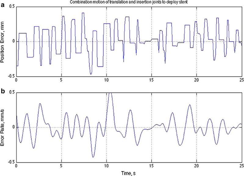
Evaluation of positional error. Combination motion of translation and insertion joints to deploy self-expanding prosthesis. a The maximum position error was <0.5 mm and b its maximum position error rate was within 0.5 mm/s
The mechanical properties of the delivery module were determined based on the maximum force and torque necessary to precisely deliver the stented valve, while taking into account the environmental friction forces. The maximum pushing force and torque were measured at the tip of the delivery device (stent) location. The air pressure used to load the system was 75 psi. The maximum force of the translation joint was 34 N, while the maximum torque of the rotation joint was 0.4 Nm. These values were determined to be sufficient to overcome environmental friction and to safely and precisely deliver the stented valve. Although it was not required, the system was capable of increasing air pressure and/or pneumatics actuators values to overcome additional friction.
MR compatibility
To ensure MR compatibility, the robotic delivery module and trocar (materials directly in contact with the subject) were designed entirely of plastic and free of any ferromagnetic materials, thus eliminating any MR-induced heating concerns. The only metal present in the VDM system was MR-compatible brass shafts in the pneumatic actuator, which were located 15 cm away from the field of view. Control electronic systems and pneumatic valves were placed outside the 5 G line. A 16-cm cylindrical MR phantom model was placed at the isocenter and scanned with and without the robotic system present. The MRI parameters used were the S1 TrueFISP sequence (TR = 436.2 ms, TE = 1.67 ms, flip angle = 45°, ECG/Trigger echo spacing = 2.9 ms).
During MR compatibility testing, the presence and motion of the robotic system inside the scanner were not found to produce any noticeable image disturbances. The observed signal-to-noise ratio (SNR) loss was 6.1 % for the VDM on standby, and 6.5 % for the VDM while in operation. The observed SNR loss for the entire robotic system was 8.2 %. SNR was calculated using the mean value of the 24 cm2 area at the center of the phantom image divided by the standard deviation of the 24 cm2 area in the lower right corner of the image and compared the SNR between two scenarios.
System-level evaluation on phantom study
System-level accuracy of the entire robotic system was tested in the phantom study (Fig. 8). Additional orientation correction was performed with axial rotation occurring at 5 °/s. Figure 9 displays progression of the orientation and position adjustment as well as the subsequent deployment of the prosthesis. The measured required force and torque for stent deployment within the 37 °C water tank were 14 N and 0.15 Nm, respectively. The required force was attributed to the friction between the stent/inner sheath and outer sheath of the delivery device during implantation. The torque required was ascribed to the friction between the delivery device and trocar valve. After the prosthesis was deployed, the distance between the edge of the tube and the end of the prosthesis was measured by calipers and defined as the position error. Ten trials were performed in total. The mean error over these ten trials was 1.14 ± 0.33 mm.
Fig. 8.

Phantom experimental setup. A phantom model was designed to emulate the dimensions of a valve replacement environment. A 25-mm-diameter plastic tube served as the aorta. A 12-mm trocar was inserted into a spherical joint. The distance from spherical joint to the end of the plastic tube was 50 mm, which is the average distance from the cardiac apex to the aorta annulus in the preclinical model
Fig. 9.

Snapshots of rtMRI-guided robotic-assisted TAVR in a phantom model. a Orientation adjustment of the prosthesis. A passive marker was attached to the stent to visualize the orientation of the stent. The first image reveals that it is aligned with one coronary ostium, while the last image demonstrates it being aligned between the two coronary ostia. b Position adjustment of the prosthesis. c Deployment of the selfexpanding prosthesis
Preclinical deployment in an animal model
Using the MRI-guided robotic assist system, the Medtronic Freestyle® SE TAVRbioprosthesis was successfully deployed in all eight swine. The animal experiment setup is shown in Fig. 10. A pre-procedural scan was performed to determine the annulus and aortic root size for valve measurement selection. On the MR images, placement of digital overlay markers provided additional visibility of critical anatomical landmarks for the operator (Fig. 6). The IFE navigation software, capable of displaying multiple oblique planes simultaneously to provide three-dimensional rendering, was used for realtime image guidance during valve deployment. Under rtMRI guidance, mean device deployment time was 61 ± 5 s and did not require rapid ventricular pacing or cardiopulmonary bypass (Fig. 11). The subjects toleratedtheprocedure without perioperative complications or adverse cardiac events (e.g., arrhythmia, myocardial infarction, hypotension, and immediate death). No significant imaging artifacts were observed.
Fig. 10.

Animal experimental setup. A prepared 55 kg Yorkshire swine was set on the MRI table with the delivery device inserted into the trocar.The robotic system displayed here was mounted
Fig. 11.

Snapshot progression of rtMRI-guided robotic-assisted TAVR deployment sequence in the long-axis view (IFE navigation display omitted). a Initial position of delivery device. b Delivery device was aligned with desired trajectory. c Delivery device advanced across the aortic valve. d, e Sheath was retracted to deploy the valve. f Valve deployed
Using CINE phased-contrast imaging sequence, the deployed valves appeared to have optimal function without evidence of turbulent flow, regurgitation or paravalvular leak. Maintenance of baseline regional and global cardiac contractility was additionally demonstrated. Post-deployment imaging verified that in all eight experiments, the stents were deployed in the correct position, within 3 mm of the native aortic valve annulus. The use of the robotic-guided system was associated with decreased distances and variation; with our previous experience in manual deployment, placement distances of 5.8 ± 2.6 mm were observed. Supplementary corroboration with necropsy was performed and further confirmed that the proximal end of the stent was positioned correctly in relation to the annulus without encroachment of the coronary ostia.
Discussion
The use of transcatheter aortic valve implantation has dramatically transformed the management of aortic stenosis and is now frequently performed in high-risk patients [30]. With indications for TAVR placement expanding, it is expected that this percutaneous intervention will soon surpass the number of open heart surgical aortic valve replacements. The focus on enhancing the delivery of transcatheter valvular prosthesis and improving their long-term durability currently remains of particular interest.
Presently, TAVR placements are primarily guided by fluoroscopy. However, this imaging technology has inherent shortcomings due to its need for radiation and nephrotoxic agents, as well as two-dimensional visual limitations and minimal soft tissue contrast. With improved multiple scan orientations, soft tissue visualization, and real-time accurate device tracking without harmful exposure, the use of rtMRI with TAVR is an attractive concept. To alleviate concerns of simultaneously manipulating a TAVR deployment device during rtMRI tracking within a confined space, we developed an MR-compatible robotic assistant system. The use of this robotic assist system was found to resolve these aforementioned challenges while concurrently providing precise and accurate deployment of a prosthetic valve.
In this study, a compact 3-DoF robotic VDM was designed and constructed for manipulating and placing a cardiac bioprosthesis during rtMRI acquisition. We have demonstrated that the robotic module possesses sufficient positional and velocity accuracy. The presence and motion of the robotic system inside the MRI scanner did not produce any demonstrable disturbances in image quality. Furthermore, the in vivo study confirmed the feasibility of a robotic-assisted TAVR under rtMRI guidance in a preclinical large animal model, which is the first such demonstration of its kind.
The importance of cardiovascular MRI in our present study cannot be understated, as it allowed for proper preplacement planning, real-time guidance, and post-placement evaluation. rtMRI proved to be successful as a sole imaging modality during the TAVR procedure, producing excellent results and no adverse events. This improved visualization with rtMRI may prove particularly useful during TAVR, as its accurate and precise deployment has been found clinically to be a major determinant in patient outcomes [31]. In combination with a robotic-aided system that offers precise dexterous device manipulation, the incidence of serious TAVR complications (particularly malpositioned stents leading to coronary ostia obstruction, embolization, or paravalvular leak) may be greatly reduced.
As this technology develops, further consideration of such a deployment system in a clinical model is likely warranted. Although this current study is principally a proof of concept and is the first study to evaluate preclinical feasibility, we recognize that the model in its present state does not fully represent the complexities that may be observed in patients. Such human pathologies, including anatomical variations and heavily calcified or severely stenotic valves, must be fully considered in an appropriate model prior to clinical application. Additional device modifications, particularly size reduction in the apparatus, is also needed before implementing this technology. At its present state, the device occupies a significant portion of the scanner bed and MRI bore. Miniaturizing the setup from its current form will be necessary to allow inclusion of patients with larger body-mass indices. This may potentially be accomplished by replacing the current straight delivery device with a flexible delivery system. Another important consideration is the procedural length while using a robotic assist device under rtMRI guidance. Recently published data from the PARTNER-I trial evaluating manually performed TAVRs using fluoroscopy noted a mean total procedural time of 85 min [32]. Although not unexpected, the use of our system did require a comparatively greater procedural length (approximately 100 min), which was primarily attributed to procedural preparation. As this technology and technique matures, and with additional operative volume, it is expected that the total procedural time will become more comparable to manually controlled fluoroscopy-based TAVRs.
We acknowledge several limitations to our robotic system in its current form. Much of the analysis and calculations of anatomical dimensions, such as the distance between the aortic annulus and coronary ostia for prosthesis deployment, were designed specifically for our animal model. Therefore, appropriate adjustments to these dimensions would be required during human application. As discussed previously, our model employed native valves without existing pathology. Further investigation with calcified or stenotic valves, potentially utilizing existing in vitro or in vivo models with LDLR gene mutations, hypercholesterolemic diet induction, or traumatic provocation, should be considered [33–36]. Furthermore, the incorporation of common interventional adjuncts, such as guidewires or balloon catheters, will be essential; many institutions now utilize balloon valvuloplasty prior to TAVR in select cases of severe aortic stenosis [37,38]. Although these components were not used in the present model, our delivery device is capable of integrating such elements and its incorporation is expected in future trials. The delivery device currently contains a special feature (axial hole with a hemostatic valve at the proximal end) that can accommodate a wide range of MR-compatible guidewires, which would be manually controlled to assist in locating the aortic annulus. The use of a guidewire in this system may not only be beneficial from a safety standpoint, but also to improve visualization. Although the image contrast of the delivery system was determined to be satisfactory in our study, an active guidewire has been shown to improve contrast when used with manual delivery devices [39]. Likewise, additional passive markers on the stent may be optically beneficial by assisting with positioning and axial orientation. Finally, it is recognized that calcifications on an aortic valve may produce imaging artifacts that result in signal voids, therefore affecting potential MRI-derived guidance [8]. Our study did not assess this consideration, as implantation was performed on non-calcified valves. However, the current use of fluoroscopy and TEE does not provide additional visualization of calcified implants and ultimately may not be clinically relevant in rtMRI-guided delivery systems. Nevertheless, additional evaluation and error analysis will be required.
In conclusion, this is the first successful demonstration of a robotic-assisted TAVR system using rtMRI guidance in an animal model. Although further optimizations and additional considerations will be required in this early iteration, a robotic assist system may provide interventional physicians with a novel set of tools that extend their ability to treat patients. The distinctive utilizations of real-time imaging and other interactive-sensing capabilities highlighted in this system can provide operators with a superior feedback ecosystem. Furthermore, the enhanced communication between imaging and robotic devices and the use of virtual fixtures for a no-fly zone could prevent incorrect or critically misaligned deployments. Such approaches with specialized robotics have the significant potential to provide a unique set of capabilities that may substantially optimize current TAVR deployments and ultimately improve procedural success and patient outcomes.
Supplementary Material
Acknowledgments
This research was made possible by funding from the Intramural Research Program of the National Heart, Lung, and Blood Institute (NHLBI), National Institutes of Health (NIH), US Department of Health and Human Services (DHHS)
Footnotes
Compliance with ethical standards
Conflict of interest All the author declare they have no conflict of interest.
Ethical approval All applicable international, national, and/or institutional guidelines for the care and use of animals were followed. All procedures performed in studies involving animals were in accordance with the ethical standards of the institution at which the studies were conducted.
Informed consent This article does not contain patient data.
References
- 1.Cribier A, Eltchaninoff H, Bash A, Borenstein N, Tron C, Bauer F, Derumeaux G, Anselme F, Laborde F, Leon MB (2002) Percutaneous transcatheter implantation of an aortic valve prosthesis for calcific aortic stenosis: first human case description. Circulation 106(24):3006–3008 [DOI] [PubMed] [Google Scholar]
- 2.Adams DH, Popma JJ, Reardon MJ (2014) Transcatheter aortic-valve replacement with a self-expanding prosthesis. N Engl J Med 371(10):967–968. doi: 10.1056/NEJMc1408396 [DOI] [PubMed] [Google Scholar]
- 3.Leon MB, Smith CR, Mack M, Miller DC, Moses JW, Svensson LG, Tuzcu EM, Webb JG, Fontana GP, Makkar RR, Brown DL, Block PC, Guyton RA, Pichard AD, Bavaria JE, Herrmann HC, Douglas PS, Petersen JL, Akin JJ, Anderson WN, Wang D, Pocock S, Investigators PT (2010) Transcatheter aortic-valve implantation for aortic stenosis in patients who cannot undergo surgery. N Engl J Med 363(17):1597–1607. doi: 10.1056/NEJMoa1008232 [DOI] [PubMed] [Google Scholar]
- 4.D’Onofrio A, Rizzoli G, Messina A, Alfieri O, Lorusso R, Sal-izzoni S, Glauber M, Di Bartolomeo R, Besola L, Rinaldi M, Troise G, GerosaG (2013) Conventional surgery, sutureless valves, and transapical aortic valve replacement: what is the best option for patients with aortic valve stenosis? A multicenter, propensity-matched analysis. J Thorac Cardiovasc Surg 146(5):1065–1070. doi: 10.1016/j.jtcvs.2013.06.047 (discussion 1070–1061) [DOI] [PubMed] [Google Scholar]
- 5.Johansson M, Nozohoor S, Kimblad PO, Harnek J, Olivecrona GK, Sjogren J (2011) Transapical versus transfemoral aortic valve implantation: a comparison of survival and safety. Ann Thorac Surg 91(1):57–63. doi: 10.1016/j.athoracsur.2010.07.072 [DOI] [PubMed] [Google Scholar]
- 6.Bavalia N, Anis A, Benz M, Maldjian P, Bolanowski PJ, Saric M (2011) Esophageal perforation, the most feared complication of TEE: early recognition by multimodality imaging. Echocardiography 28(3):E56–59. doi: 10.1111/j.1540-8175.2010.01291.x [DOI] [PubMed] [Google Scholar]
- 7.Daniel WG, Erbel R, Kasper W, Visser CA, Engberding R, Sutherland GR, Grube E, Hanrath P, Maisch B, Dennig K, Schartl M, Kremer P, Angermann C, Iliceto S, Curtius JM, Mügge A (1991) Safety oftransesophageal echocardiography. A multicenter survey of 10,419 examinations. Circulation 83(3):817–821 [DOI] [PubMed] [Google Scholar]
- 8.Kahlert P, Parohl N, Albert J, Schafer L, Reinhardt R, Kaiser GM, McDougall I, Decker B, Plicht B, Erbel R, Eggebrecht H, Ladd ME, Quick HH (2012) Towards real-time cardiovascular magnetic resonance guided transarterial CoreValve implantation: in vivo evaluation in swine. J Cardiovasc Magn Reson 14:21. doi: 10.1186/1532-429X-14-21 [DOI] [PMC free article] [PubMed] [Google Scholar]
- 9.Lederman RJ (2005) Cardiovascular interventional magnetic resonance imaging. Circulation 112(19):3009–3017. doi: 10.1161/CIRCULATIONAHA.104.531368 [DOI] [PMC free article] [PubMed] [Google Scholar]
- 10.Horvath KA, Mazilu D, Kocaturk O, Li M (2011) Transapical aortic valve replacement under real-time magnetic resonance imaging guidance: experimental results with balloon-expandable and selfexpanding stents. Eur J Cardiothorac Surg 39(6):822–828. doi: 10.1016/j.ejcts.2010.09.030 [DOI] [PMC free article] [PubMed] [Google Scholar]
- 11.McVeigh ER, Guttman MA, Lederman RJ, Li M, Kocaturk O, Hunt T, Kozlov S, Horvath KA (2006) Real-time interactive MRI-guided cardiac surgery: aortic valve replacement using a direct apical approach. Magn Reson Med 56(5):958–964. doi: 10.1002/mrm.21044 [DOI] [PMC free article] [PubMed] [Google Scholar]
- 12.Eslami S, Shang W, Li G, Patel N, Fischer GS, Tokuda J, Hata N, Tempany CM, Iordachita I (2015) In-bore prostate transperineal interventions with an MRI-guided parallel manipulator: system development and preliminary evaluation. Int J Med Robot. doi: 10.1002/rcs.1671 [DOI] [PMC free article] [PubMed] [Google Scholar]
- 13.Fischer GS, Iordachita I, Csoma C, Tokuda J, Dimaio SP, Tempany CM, Hata N, Fichtinger G (2008) MRI-compatible pneumatic robot for transperineal prostate needle placement. IEEE ASME Trans Mechatron 13(3):295–305. doi: 10.1109/TMECH.2008.924044 [DOI] [PMC free article] [PubMed] [Google Scholar]
- 14.Krieger A, Iordachita II, Guion P, Singh AK, Kaushal A, Menard C, Pinto PA, Camphausen K, Fichtinger G, Whitcomb LL (2011) An MRI-compatible robotic system with hybrid tracking for MRI-guided prostate intervention. IEEE Trans Biomed Eng 58(11):3049–3060. doi: 10.1109/TBME.2011.2134096 [DOI] [PMC free article] [PubMed] [Google Scholar]
- 15.Patriciu A, Petrisor D, Muntener M, Mazilu D, Schar M, Stoianovici D (2007) Automatic brachytherapy seed placement under MRI guidance. IEEE Trans Biomed Eng 54(8):1499–1506. doi: 10.1109/TBME.2007.900816 [DOI] [PMC free article] [PubMed] [Google Scholar]
- 16.Stoianovici D, Kim C, Srimathveeravalli G, Sebrecht P, Petrisor D, Coleman J, Solomon SB, Hricak H (2013) MRI-safe robot for endorectal prostate biopsy. IEEE ASME Trans Mechatron 19(4):1289–1299. doi: 10.1109/TMECH.2013.2279775 [DOI] [PMC free article] [PubMed] [Google Scholar]
- 17.Ho M, McMillan A, Simard JM, Gullapalli R, Desai JP (2011) Towards a meso-scale SMA-actuated MRI-compatible neurosurgical robot. IEEE Trans Robot 99:1–10. doi: 10.1109/TRO.2011.2165371 [DOI] [PMC free article] [PubMed] [Google Scholar]
- 18.Lang MJ, Greer AD, Sutherland GR (2011) Intra-operative robotics: NeuroArm. Acta Neurochir Suppl 109:231–236. doi: 10.1007/978-3-211-99651-5_36 [DOI] [PubMed] [Google Scholar]
- 19.Li G, Su H, Cole GA, Shang W, Harrington K, Camilo A, Pilitsis JG, Fischer GS (2015) Robotic system for MRI-guided stereotactic neurosurgery. IEEE Trans Biomed Eng 62(4):1077–1088. doi: 10.1109/TBME.2014.2367233 [DOI] [PMC free article] [PubMed] [Google Scholar]
- 20.Masamune K, Kobayashi E, Masutani Y, Suzuki M, Dohi T, Iseki H, Takakura K (1995) Development of an MRI-compatible needle insertion manipulator for stereotactic neurosurgery. J Image Guided Surg 1(4):242–248. doi: 10.1002/(SICI)1522-712X(1995)1:4<242:AID-IGS7>3.0.CO;2-A [DOI] [PubMed] [Google Scholar]
- 21.Hempel E, Fischer H, Gumb L, Hohn T, Krause H, Voges U, Bre- itwieser H, Gutmann B, Durke J, Bock M, Melzer A (2003) An MRI-compatible surgical robot for precise radiological interventions. Comput Aided Surg 8(4):180–191 [DOI] [PubMed] [Google Scholar]
- 22.Tsekos NV, Ozcan A, Christoforou E (2005) A prototype manipulator for magnetic resonance-guided interventions inside standard cylindrical magnetic resonance imaging scanners. J Biomech Eng 127(6):972–980 [DOI] [PubMed] [Google Scholar]
- 23.Li M, Kapoor A, Mazilu D, Horvath KA (2011) Pneumatic actuated robotic assistant system for aortic valve replacement under MRI guidance. IEEE Trans Biomed Eng 58(2):443–451. doi: 10.1109/TBME.2010.2089983 [DOI] [PubMed] [Google Scholar]
- 24.Chinzei K, Kikinis R, Jolesz FA (1999) MR compatibility of mechatronic devices: design criteria In: Medical image computing and computer-assisted intervention-MICCAI’99. Springer, pp 1020–1030 [Google Scholar]
- 25.Schenck JF (2000) Safety of strong, static magnetic fields. J Magn Reson Imaging 12(1):2–19 [DOI] [PubMed] [Google Scholar]
- 26.Mazilu D, Li M, Kocaturk O, Horvath KA (2012) Self-expanding stent and delivery system for aortic valve replacement. J Med Device 6(4):410061–410069. doi: 10.1115/1.4007750 [DOI] [PMC free article] [PubMed] [Google Scholar]
- 27.Li M, Mazilu D, Horvath KA (2008) Robotic system for transapical aortic valve replacement with MRI guidance. Med Image Comput Comput Assist Interv 11(Pt 2):476–484 [DOI] [PMC free article] [PubMed] [Google Scholar]
- 28.Kapoor A, Wood B, Mazilu D, Horvath KA, Li M (2009) MRI-compatible hands-on cooperative control of a pneumatically actuated robot. IEEE Int Conf Robot Autom 2009:2681–2686. doi: 10.1109/R0B0T.2009.5152541 [DOI] [PMC free article] [PubMed] [Google Scholar]
- 29.Horvath KA, Mazilu D, Guttman M, Zetts A, Hunt T, Li M (2010) Midterm results of transapical aortic valve replacement via realtime magnetic resonance imaging guidance. J Thorac Cardiovasc Surg 139(2):424–430. doi: 10.1016/j.jtcvs.2009.08.005 [DOI] [PMC free article] [PubMed] [Google Scholar]
- 30.Hamm CW, Arsalan M, Mack MJ (2015) The future of transcatheter aortic valve implantation. Eur Heart J. doi: 10.1093/eurheartj/ehv574 [DOI] [PubMed] [Google Scholar]
- 31.Geisbusch S, Bleiziffer S, Mazzitelli D, Ruge H, Bauernschmitt R, Lange R (2010) Incidence and management of CoreValve dislocation during transcatheter aortic valve implantation. Circ Cardiovasc Interv 3(6):531–536. doi: 10.1161/CIRCINTERVENTI0NS.110.944983 [DOI] [PubMed] [Google Scholar]
- 32.Alli O, Rihal CS, Suri RM, Greason KL, Waksman R, Minha S, Torguson R, Pichard AD, Mack M, Svensson LG, Rajeswaran J, Lowry AM, Ehrlinger J, Tuzcu EM, Thourani VH, Makkar R, Blackstone EH, Leon MB, Holmes D (2015) Learning curves for transfemoral transcatheter aortic valve replacement in the PARTNER-I trial: Technical performance. Catheter Cardiovasc Interv. doi: 10.1002/ccd.26120 [DOI] [PubMed] [Google Scholar]
- 33.Sider KL, Blaser MC, Simmons CA (2011) Animal models of calcific aortic valve disease. Int J Inflam 2011:364310. doi: 10.4061/2011/364310 [DOI] [PMC free article] [PubMed] [Google Scholar]
- 34.Goncerz G, Tomaszewski KA, Pasternak A, Glowacki R, Wrobel A, Rokita E, Podolec P (2014) A novel in-vitro model of human aortic valve mineralization. J Heart Valve Dis 23(5):545–549 [PubMed] [Google Scholar]
- 35.Bowler MA, Merryman WD (2015) In vitro models of aortic valve calcification: solidifying a system. Cardiovasc Pathol 24(1):1–10. doi: 10.1016/j.carpath.2014.08.003 [DOI] [PMC free article] [PubMed] [Google Scholar]
- 36.Honda S, Miyamoto T, Watanabe T, Narumi T, Kadowaki S, Honda Y, Otaki Y, Hasegawa H, Netsu S, Funayama A, Ishino M, Nishiyama S, Takahashi H, Arimoto T, Shishido T, Miyashita T, Kubota I (2014) A novel mouse model of aortic valve stenosis induced by direct wire injury. Arterioscler Thromb Vasc Biol 34(2):270–278. doi: 10.1161/ATVBAHA.113.302610 [DOI] [PubMed] [Google Scholar]
- 37.Ben-Dor I, Maluenda G, Dvir D, Barbash IM, Okubagzi P, Torgu-son R, Lindsay J, Satler LF, Pichard AD, Waksman R (2013) Balloon aortic valvuloplasty for severe aortic stenosis as a bridge to transcatheter/surgical aortic valve replacement. Catheter Cardiovasc Interv 82(4):632–637. doi: 10.1002/ccd.24682 [DOI] [PubMed] [Google Scholar]
- 38.Ali O, Marmagkiolis K, Cilingiroglu M (2015) Combined rotational atherectomy and aortic balloon valvuloplasty as a bridge to transcatheter aortic valve replacement. Rev Port Cardiol 34(12):775.e1–775.e4. doi: 10.1016/j.repc.2015.03.028 [DOI] [PubMed] [Google Scholar]
- 39.Sonmez M, Saikus CE, Bell JA, Franson DN, Halabi M, Faranesh AZ, Ozturk C, Lederman RJ, Kocaturk O (2012) MRI active guidewire with an embedded temperature probe and providing a distinct tip signal to enhance clinical safety. J Cardiovasc Magn Reson 14:38. doi: 10.1186/1532-429X-14-38 [DOI] [PMC free article] [PubMed] [Google Scholar]
Associated Data
This section collects any data citations, data availability statements, or supplementary materials included in this article.